Updated again to add some investigation into the edge case errors when the CLF is baked into a single 3D LUT (as will often be the case for hardware implementations).
But in fact I think it is simply the result of a negative offset followed by a 0-1 clamp, applied by the ASC CDL node.
A simple 1D illustration:
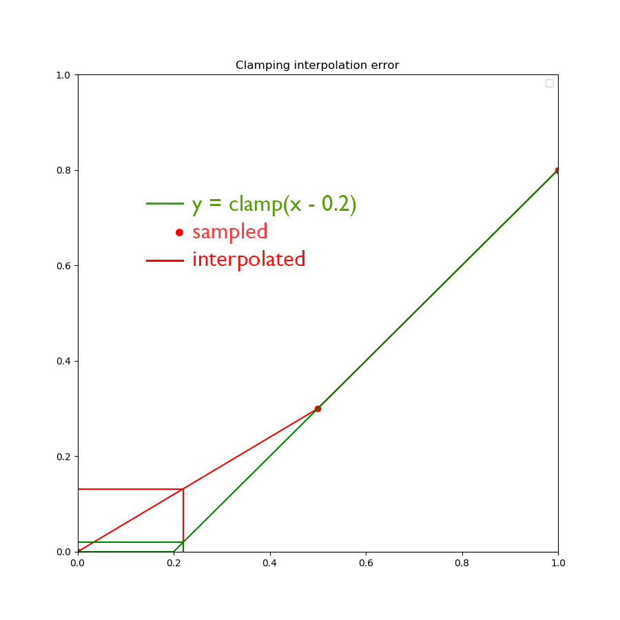
Negative offset, followed by clamping 0-1 will produce a hard corner in the true output (the green line). Sampling either side of that corner, and then interpolating (the red line) will give an inaccurate result, particularly near the cusp.
(This is obviously an exaggerated example, with a large offset and small number of samples to make the point)
And here is a plot of the actual output of the CLF applied to a green ramp from 0-1 (with red and blue held at zero).

Looking at that it is obvious why there will be interpolation errors in the red channel with a 33^3 LUT3D in the interval above g = 0.75 (the small ticks on the axis represent the intervals of a 33^3 cube).
Here is a plot of the same ramp processed through the baked single 3D LUT:
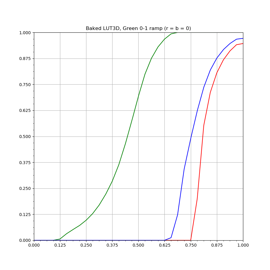
These errors occur at the boundaries of the cube, so are unlikely to produce visible artefacts in photographic images. The preview tier is intended for situations such as on-set, and the output of a camera is unlikely to produce ACEScct values of either 0 or 1.
UPDATE 2020-10-13
I have added more to the Colab following the last meeting to investigate if clamping the image values to those which could occur in a real image (ACEScct equivalent of 0-100 linear was suggested) improved the situation.
Unfortunately while doing this reduces the magnitude of the max code value error (99 instead of 116) it is still significant. I believe that it is because the CDL is still pushing values negative (and then clamping them to zero) due to the combined effect of the negative offsets and the saturation of 1.2. So you still end up with kinks in the curve either side of a colour which could possibly occur (although the colours which cause the largest errors are still unlikely from a real camera, because they have two channels at zero in linear AP1).
But even for the ColorChecker in the test image, the purplish blue patch has an error of 22 10-bit code values in the red channel with the baked LUT, and the blue patch an error of 12 code values. The difference in the purplish blue patch is clearly visible to the eye when toggling between the full CLF and the baked LUT.