Gamut Mapping Part 2: Getting to the Display

What For

If we are going to use a chromaticity-preserving tonescale, we will need tools to achieve the aesthetic image rendering we want. One of these image rendering aspects that I think is quite important is the handling of color. Both brightly saturated color, and the behavior of film (and most display rendering transforms) where highlights become increasingly desaturated as the display-referred image approaches 100% output.

How to Do It

I have been playing around with various perceptually uniform opponent colorspaces. In particular JzAzBz. I’ve had some good results compressing chromaticity values in this colorspace. The Az and Bz components encode 4 hue directions: red/green, and blue/yellow.

Applying a compression function on these 4 axes gives pretty good control over output color. A clever person could probably figure out how to encode this as a continuous lookup instead of a per-channel adjustment.

Since the origin at 0 is the achromatic axis, we can scale down the values of Az and Bz to reduce saturation. And the cool thing about this scaling is that the path the hues take towards neutral looks plausible: no noticeable hue shifting.

The cool thing about this is that it can be done in scene linear. I think it helps having access to that larger range of data.

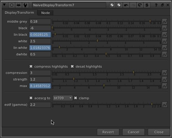
So to accomplish a reduction in gamut volume as a function of brightness, I am multiplying AzBz to 0 as a function of a log-encoded brightness range (chosen creatively). In the nuke setup I’ve also included a node called GamutCompress which applies a compression function to AzBz above a specified threshold. Something like this sketch might be useful if we wanted to do more specific adjustments to certain hue ranges.

Look at Some Pictures

Here’s a big giant folder full of rendered test images to look at:


Dropbox’s gallery mode sucks so feel free to download the images to view them.

The test images I’m using are from the following sources:


And here is the nuke script used to generate the “Weighted Power Norm Tonescale, JzAzBz HL Compress” images.
20190119_gamut_mapping.nk (124.3 KB)

Conclusions

Generally I think the rendering is quite good considering this is just a first test. The amount and range of the highlight gamut compression was created creatively and is not scientific at all. It could be scientific or more creatively based on the reference behavior of say a film stock.

The rendering of the colors seems like a nice starting point for further grading, at least to my eye.

I think it’s important that we think about what goes in the clean simple default display rendering transform and what goes in perhaps an optional “default LMT”.

If we were to create a default LMT, a couple of things I would add:

  • The rendering of orangish colors doesn’t have that nice yellowish cast that is pleasing (at least to my eye) in the ACES transform. The fire especially looks pretty unnaturally red.
  • Skin tones could use some love, maybe some smoothing, darkening and increasing saturation of red-oranges
  • Probably other stuff that a professional colorist could spot!

I hope some of this is useful, and I’m curious to hear any and all thoughts on the subject of handling and manipulating color in the context of a display rendering transform!

6 Likes

Nice work Jed!

I would tend to agree with that, might be a problem on HDR displays too!

Cheers,

Thomas

Very interesting approach!

All yellowish colours seem to get excessively desaturated. Look at the yellow box on the shelf behind his head in this image. It’s not really a highlight at all, but is dramatically affected by the desat. I do of course realise that this is a first pass with parameter values that are not necessarily optimal.

Agreed. I think this is what @daniele was hinting at about the downsides of perceptually uniform opponent colorspaces like JzAzBz for doing manipulations like this: the limited range in the yellows.

I would be very keen to hear a suggestion for a different technical approach to achieve a controllable and good looking desaturation of highlights above a certain threshold for different hues.

Meanwhile I did push this setup forward a bit more last night with some improved results by doing a per-axis desaturation in JzAzBz. Here is a nuke script to replace the highlight desat setup in the previous one:
20190121_refined_highlight_desat.nk (38.8 KB)

Despite the increased number of nodes the math is very simple: it’s just adjusting the brightness thresholds for each color axis. Shifting up the yellow axis significantly helps preserve skin tones, makes fire look orange again, and generally improves the look of everything, while still removing the ghastly artifacts on warm light sources like the sun and the lamp behind the girl on the couch.

Ignore my ignorance if this is totally wrong, but what would happen if you’re using the colorspace oklab instead of JzAzBz?

I actually suggested that at last VWG meeting :slight_smile:

2 Likes

This is a first indicator of “wrong domain” . If you start to do stuff per hue it becomes questionable why you would go into that space anyway…
And what does “perceptually uniform” actually mean in this context?

3 Likes

I tried using a few different perceptually uniform colorspaces to do this: Oklab, IPT, ICtCp, JzAzBz - they all yield pretty similar results, just slightly shifting the behavior of the hue as it travels back to neutral.

I guess I started out thinking of this problem more as a gamut mapping problem, looking at @ChrisBrejon 's lightsaber render and other very saturated hues. Using a perceptually uniform space made sense in my color science neophyte brain in order to try to preserve “natural looking” hues as they desaturate. This thinking may be totally incorrect and not at all what a perceptually uniform colorspace is designed for.

Attempting to desaturate highlights (and shadows) as a component of a chromaticity preserving display rendering should probably be done in a much simpler way. As @daniele said, in a different domain.

I don’t think it is incorrect quite the opposite, but the way they model our perception is maybe not appropriate for our needs. Also, given their design simplicity, they cannot be good at predicting lightness, chroma and hue at same time. Their is so much that a 3x3 matrix and a power-like function can do! The other space that might be also interesting to look at is IgTgPg, even though it does not produce great gradients!

I will render some hue stripes later for all of them.

Don’t get me wrong, I think this is all great, but also keep in mind that those colour space were never designed for the task at hand.

Yes, this was my point! :slight_smile:

Disclaimer: The following is not an approach I would suggest be used for producing good looking images, but merely an interesting and informative exercise to better understand the problem at hand.

Back to Basics
The last several days I’ve been thinking about the highlight desaturation problem. With display rendering there are a lot of intertwined problem areas, and it’s very easy (at least for me) to get confused. Like earlier when I was thinking about gamut compression and highlight desaturation as one problem. They are two different problems. Related, but not the same.

So how can we simplify and isolate these problem areas? We could ignore “out of display gamut” issues. We could ignore tonemapping or intensity scaling issues.

NaiveDisplayTransform
In an effort to simplify and focus on highlight compression and desaturation, I made a nuke node called NaiveDisplayTransform. As the name suggests, it undertakes a very naive approach to mapping scene-linear to display-linear.

  • Maps an input range in scene-linear from linear_start to linear_end, defined in stops above and below middle gray, to an output range in display linear from 0 to display linear end.
  • From display linear end to 1.0, apply a compression curve to the scene linear values. The compression curve compresses infinity to a value of limit stops above linear end. In other words: if limit is 1, all highlight values from linear end to infinity will be compressed into a range of 1 stop. The bigger limit is, the more range there will be for the compressed highlight values.
  • Where highlight values are compressed, desaturate.

The simplest possible display transform would be a linear to linear mapping. We take a range of scene-linear values and remap them to a range of display-linear values. We apply the inverse EOTF. The scene linear values are displayed directly on the display, up until the values clip. For the range that can be displayed, (ignoring spectral emission differences, calibration, and other complications) there should be a 1 to 1 correspondence between scene luminance and display luminance.

Since pictures are easier to understand than words (at least for me), here’s a video demonstration of the concept and the tool.

When Channels Clip
With a simple 1 to 1 mapping, we can focus on how highlight values behave as they approach 100% display emission.

With no highlight compression and no desaturation, hue shifts are introduced for non achromatic colors, because as one component clips, the other components continue to increase. So we need some way to “handle” these components as they increase in brightness, to remove hue shifts as the components approach clipping. To do this we can move the components toward the achromatic axis as their luminance increases.

Here’s a video demo with some interesting plots of what’s going on.

Technical Approach
Amidst an extended conversation with @Troy_James_Sobotka (thanks for your patience with my stupid questions), I got to thinking about the Inverse RGB Ratios approach that we ended up using in the Gamut Mapping VWG. In that approach we were using the inverse rgb ratios to push out of gamut values back towards the achromatic axis.

inverse_rgb_ratio = max(r,g,b) - rgb

If we instead used a constant value that we wanted to “collapse” our components towards, we could do

lin_max = 4.0
inverse_rgb_ratio = lin_max - rgb

If we add inverse_rgb_ratio to rgb, we will get lin_max everywhere. But if we modulate inverse_rgb_ratio by some factor which describes how much we want to desaturate, then we get a simple and effective method of highlight desaturation.

The best way I’ve found so far (and I think there’s better approaches), is to modulate the inverse_rgb_ratio by the complement of the compression factor. When we use the norm to do the highlight compression, we do

norm = max(r,g,b)
intensity_scale = compress(norm) / norm
scaled_rgb = intensity_scale * rgb
compression_factor = 1 - intensity_scale

intensity_scale here is kindof like the derivative of the curve: it represents how much the compress function is altering the norm.

Then we can do

lin_max = 4.0
inverse_rgb_ratio = lin_max - c
desaturation_factor = inverse_rgb_ratio * compression_factor
desat_rgb = rgb + desaturation_factor

Here’s a video walkthrough of the technical approach.

Considering how stupid and simple this approach is it actually doesn’t look half bad in my aesthetic opinion.

Here’s a video of how the transform looks on some example test images.

And finally here’s the NaiveDisplayTransform node if you want to play around with it. No blinkscript so it should work fine in Nuke Non-Commercial.

EDIT - since the above link points to a gist that has been updated, here is the original nuke script as it existed at the time of this post: NaiveDisplayTransform_v01.nk (18.3 KB)

Next step for me is seeing how this same approach might be applied with a more traditional sigmoidal curve for input range compression.

Just wanted to share what I’ve been up to in case it’s useful for anyone here.

4 Likes

Nice stuff !

I have been playing with the Nuke script this week and it has given me interesting results. I think it is great to go back to basics in a way (at least for me !) in order to fully understand what we are dealing with.

I have done a quick image of the tool’s options/parameters if anyone is interested. It helped me to grasp better these concepts.

I am looking forward to future updates of the tool. Let me know if my “mockup” is wrong or incorrect, I’d be happy to update it.

Chris

1 Like

Thanks @ChrisBrejon! Now that you’ve made this excellent diagram explaining everything, I reworked the parameters a bit to hopefully make it more clear what is going on. I realized after reading my post again with a fresh brain that there were some things that could be made more clear and simplified.

screenshot_2021-01-29_15-34-36

I reworked the parameters so that the naming is more consistent, and so that the linear value that is calculated is displayed right below the value you are adjusting.

Everything functions the same way except for the limit parameter, which I’ve changed the name of to compression and altered how it works. Now instead of mapping infinity to the value that you specify in stops above lin_white, you specify a value in stops above lin_white, and that value is compressed to display maximum. In other words, compression calculates the max value, which is the maximum scene-linear value that will be represented on the display.

I’ve also exposed the strength parameter, so you can adjust the slope of the compression curve. It seems like you need control over this to get the best results, depending on the dwhite and compression value you have set.

As before here’s a little video demo of the updates and changes I’ve made.

EDIT - Here is the nuke script described in the above screenshot
NaiveDisplayTransform_v02.nk (6.9 KB)

I also made some further usability improvements and additional parameters, which I did not make a post about. Here is that updated version:
NaiveDisplayTransform_v03.nk (7.6 KB)

EOTF should be EOTF^{-1} or Inverse\ EOTF and we should try to remove gamma if possible too!

3 Likes

Thanks @Thomas_Mansencal ! Indeed, that’d be much better this way ! I’ll update the sketch asap.

Cool @jedsmith ! I’ll give it a try next week ! Great update and video explanation. Thanks for sharing !

Jed,

Thanks so much for the work and thoughts. There’s a lot here to react to. I’ll just throw out a few points to consider.

  • I don’t know if I’d characterize highlight desaturation as a problem. Sometimes it’s the effect you want, and sometimes it isn’t.

  • I think there’s value in recognizing, either conceptually or in practice, that the rendering transform, at some point, should yield display colorimetry and turning that display colorimetry into a signal is a process that’s pretty straight forward and objective (e.g. convert to display primaries, encoded with inverse EOTF, etc). The only wrinkle is gamut mapping. We’ve talked about this We’ve talked about the separation of rendering and creation of the display encoding a bunch in the past and it’s fine to separate that out but it’s not really part of the rendering discussion per-say. We discussed the concept in this document. http://j.mp/TB-2014-013.

  • Displaying linear scene data on a display, within the limits of that display’s capability, is a helpful tool at times. With the ACES 1.0 work we did that a lot. I also suggested doing that during the gamut mapping work to help visualize the ACES data. Generally speaking, to make a reasonable reproduction on an output medium you’re going to need to compensate for viewing flare and the surround associated with the display environment (among other things). But those two usually end up increasing the slope of the tone scale. I’d highly recommend Chapter 5 of Digital Color Management: Encoding Solutions Second Edition which does the topic way more justice than I ever could.

3 Likes

Hey Alex, thanks for the thoughts!

Thank you! I’m in this to learn, and I appreciate the reference. I’ll take a look at this. As I mentioned in my disclaimer above, this experiment is purely to better understand the problem at hand, not something I am putting forward as something to be considered as an aesthetically pleasing display rendering.

My Apologies for the imprecise terminology. As I’ve mentioned in the past, I could more accurately be referred to as a “Color Pragmatist” than a “Color Scientist”.

The problem that I’m attempting to understand in my ramblings above could perhaps be more precisely expressed.

What I’m trying to understand is what happens to color when approaching and passing the “top end” or max luminance of a display-referred gamut boundary. That is, for an rgb triplet which contains a color that is too bright to be represented on a display device, what happens to hue when one channel clips to display maximum and other channels do not. These unnatural renderings of hue in the upper portions of the luminance range is why I think gamut reduction as luminance approaches display maximum is critically important to rendering a good looking picture, rather than an aesthetic preference. The example photos that you posted here show the issue pretty clearly.

Of course the implicit assumption in all of this is that we would want a chromaticity preserving tonescale rather than a per-channel rgb approach which applies this luminance-gamut limiting as a byproduct.

Can you elaborate on why gamut mapping should not be a part of the rendering discussion? Surely there should be some type of handling for colorimetry that can not be reproduced on the display device in the default display rendering transform? I’m sure it’s something silly I didn’t think of, but like I said I’m in this to learn :slight_smile:

2 Likes

Hi Jed,

can you post again a link to your latest version of your Nuke Gizmo? Thanks.