High light fix and premature desaturate

Background: I’m a game dev, graphic engineer, new to ACES (not even know about it few month ago), have some superficial knowledge about spectrum, color space and so.
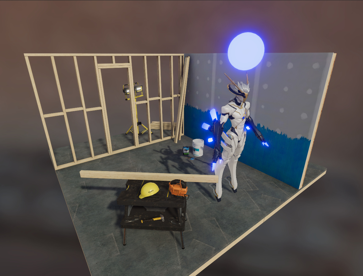
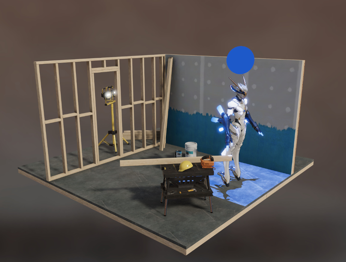
Several month ago, as Unity3D with Universal rendering pipeline begin to offer ACES tone mapping option, and our game look MUCH better with it, we decide to switch to ACES. Our artists soon discover that bright blue turn magenta with ACES tone mapping on. Just like sphere and crystal on robot’s fingers and arms in following image.


With some days of head scratching googling, I manage to find high light fix matrix from Scott Dyer. With the high light fix matrix, magenta artefacts are gone, and over all picture looks much better, everyone in our team was happy.

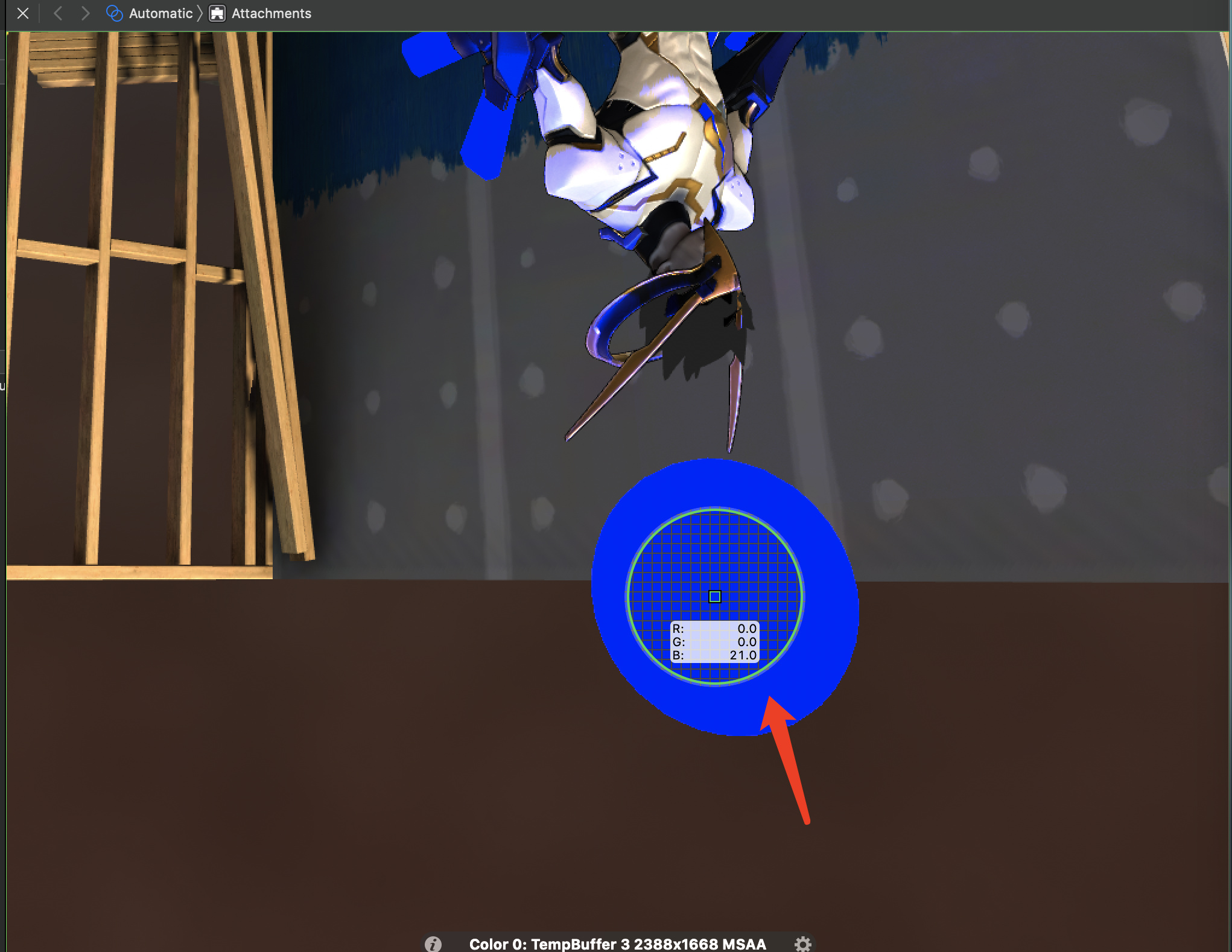
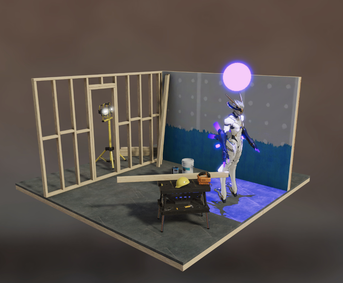
After several month of developing and assets creating, our visual effect artist told me that they find out that they lose access to high saturate color. I first respond with my gut and tell them this is by design, bright light saturate all cone cells, wash out and desaturate, this behavior mimic human vision. Until they show me an example that even sRGB linear value lower than 1 still desaturate heavily, like the sphere below, my shader simply output #0000FF in sRGB color space, it became #0056d0 after tone mapping.

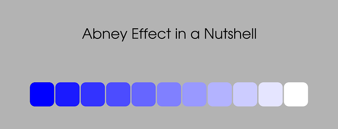
More head scratching, googling, trial and error, I find out it’s the highlight fix make color with luminance around 1 desaturate premature. But this time I can’t find any solution from internet, except an open issue and a post it mentions.

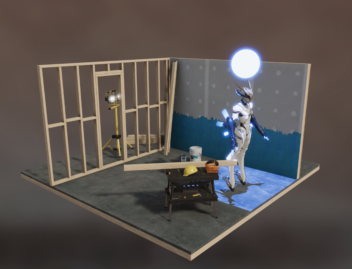
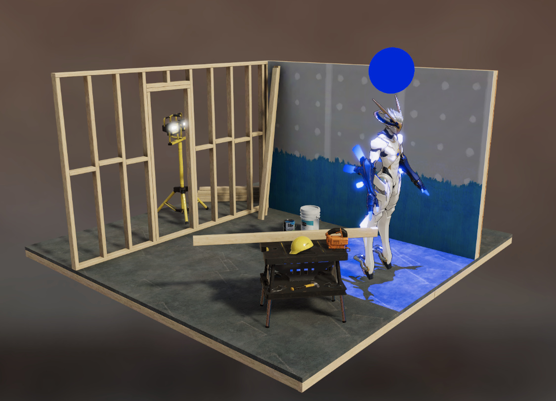
Desperately, my poor programmer’s choice is to lerp the result from high light fix and original color like this with a _HighLightFix around 0.35 and add some contrast and saturation with color adjustment post process.

aces = lerp(aces, ACES_highlight_fix(aces), _HighLightFix)

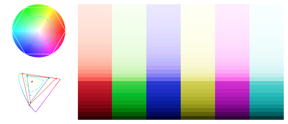
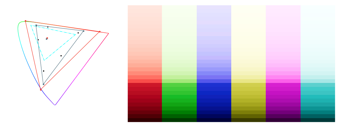
These voodoo works, I can now produce very saturate color without those magenta artefacts, just like this:

Our artists accept this happily, but I’m still with little confidence: What if something else look wrong several month later? Will this trick broke at some edge case?
My question is now, why the highlight fix will lead to premature desaturation? Is it related to the issue ? Will the lerping trick shot on my toes sometimes later? Is there any more elegant solution to this kind of problem?

Thank you very much for reading such a long post, and any advice would be appreciate!

1 Like

Welcome Unkstar! I’m quite sure someone will respond to your post shortly. Happy to have you in the community.

Hello @unkstar,

very interesting post. Thanks for sharing with us these images and examples.
I have been facing the same issues at our studio and my short answer is : it is a limitation of the ODT.
If I understood correctly, this problem could be potentially be fixed in ACES 2.0.

The solution you have come with is quite interesting. In most studios it is the responsibility of the colorist to fix these issues. Some smarter people would probably explain this better than me but the only long-term solution to my knowledge is gamut mapping.

The first example of the blue going magenta is called Hue Skews and this effect is pretty much undesirable. The issue basically is since we go from blue to white, what should be in-between ? Blue is probably the color you notice the most this effect (since it is the darkest primary ?) but you may notice green going yellow and red going orange when overexposed. @Troy_James_Sobotka could give some great advice on this matter.

abney_effect

Another interesting answer was given to me by @nick :

There are a few elements in the RRT and ODT that affect blue, but this is generally because pure sRGB blue when transformed into ACEScg ends up with a small green component and a slightly larger red component. sRGB (0, 0, 1) corresponds to ACEScg (0.04737, 0.01345, 0.86980). When you increase the exposure, to around 2.4 stops, the blue channel reaches 1.0 when it went through the sRGB output transformation. Since the red channel is about four times larger than the green channel, as the exposure increases to the point where all channels are 1.0 via an SDR output transformation, the red and green channels change from negligible (but with 4x more red than green) to significant, but with blue having peaked at 1.0, it cannot therefore go higher. Thus, the color changes from magenta to white.

Basically the issue is present with any curve that asymptotes at 1 like Reinhard or Hable if I have understood correctly. I have written a bit on the topic back in the day. But I am clearly no expert. I am pretty sure you will get some great answers in the next hours ! :wink: This particular topic is so interesting !

My tuppence,

Chris

Thank you for replying, @ChrisBrejon !
As game graphic is interactive, fine tune every single frame by colorist is simply impossible. (And we don’t have any dedicate colorist employed too!)
With @nick 's explanation, I think I understand the reason of hue skew now. The remaining question is: Why will highlight fix matrix from @sdyer cause color with luminance between 0.8 to 1.0 desaturate so early?
The lerping trick is just graphic engineer’s common practice while we encounter something we think it should be parameterized, raise saturation is also simple instinct to counter desaturation. But as I play with those post processing parameter today, I find out that raising contrast help much more than raising saturation, it not only help cancel out desaturation introduce by the highlight fix, but also help cancel out color skew introduce by lerping between original color and highlight fixed one. Surprisingly, I find that if I raise contrast high enough, I can remove magenta without highlight fix matrix, but the resulting image is not pleasing at all, though. Following image is only color adjust by adding contrast and saturation, without highlight fix.

@stobenkin Shall I change category of this post to “Video Game/Realtime”?

1 Like

yes, category change would be great! we’d be happy to hear about any other experiences you or others are having using ACES in gaming or with realtime engines! Thanks for asking.

That effect is clearly illustrated here (ignore the unrelated colour fringing on the text – that is a GIF artefact):
sRGB_blue_magenta

The “blue highlight fix” LMT is not really intended to counter the hue skews at high exposure, but rather the very harsh artefacts resulting from values which are outside the AP1 gamut. Because you are starting with an sRGB colour, it is well within AP1, so that LMT is not really an appropriate fix.

I would suggest that rather than starting out by thinking about sRGB source colours, you choose colours which give the result you want when viewed through an ACES output transform. So don’t necessarily start with sRGB(0, 0, 1) if you want a saturated blue. Choose a colour which may be outside the sRGB gamut (but in AP1) which gives the result you are after. As as example, here is a colour which starts blue at normal exposure, but goes through a more cyan tint as it goes into over-exposure. Is it “right”? The answer to that is subjective. But it may be more the sort of thing you are looking for aesthetically (bearing in mind that sRGB is not capable of displaying a colour which is both bright and blue).
sRGB_blue_magenta_3

2 Likes

As a counterpoint, this feels like a horrible kludge working around a flaw.

It would seem entirely acceptable to expect the radiometric ratios present in the scene to render with accuracy, based on some chosen metric, via a Display Rendering Transform, as viable within a given output gamut volume, and gamut compressed to an appropriate output where impossible.

After some digging around the forum and documents, I’m a little confuse: Is ACEScg color value out of [0.0, 1.0] means out of AP1 gamut?
Since we are using HDR rendering, with bright light or emissive material, color with value much higher than 1.0 is very likely to appear in scene.
Let me explain a little bit about the rendering process of Unity3D with Universal Rendering Pipeline here, Unity3D with linear HDR setup, feed shaders with linear sRGB value, such as albedo texture, light color, etc…all rendering happen in linear sRGB space, then convert to ACEScc/ACEScg to do grading and tonemapping. Finally, tone mapped ACEScg result would be convert back to AP0, then feed to RRT and ODT, and put on display.
As I check the internal HDR render buffer, the magenta sphere and crystal has linear sRGB value as high as 21.0 in blue channel, apparently it will be over 1.0 after converting to ACEScg.

Do I need to use highlight fix LMT in such case? Or there is better way around?

bearing in mind that sRGB is not capable of displaying a colour which is both bright and blue

As you mention sRGB is not capable of display color both bright and blue, I’ve considered modifying the rendering pipeline to do all rendering in ACEScg, but after some careful research, I decide not to. The reason behind the decision is:

  1. Without realtime indirect lighting, benefit from rendering in ACEScg seems minimal, and we can not afford realtime GI with the limited GPU budget of our target platform.
  2. This require our team to adopt a full ACES process, since most DCC software we use, such as Photoshop, Substance painter, can not support ACES very well. Our artists team is not familiar with ACES and limitation of deadline and development budget.

I would suggest that rather than starting out by thinking about sRGB source colours, you choose colours which give the result you want when viewed through an ACES output transform. So don’t necessarily start with sRGB(0, 0, 1) if you want a saturated blue. Choose a colour which may be outside the sRGB gamut (but in AP1) which gives the result you are after.

Yes, I do have a small tool like this for our artist to do the trick, it do color pick from design art, go through invert ODT and invert RRT, then output the value convert back to sRGB. But with the limitation of sRGB, It only work with albedo color, very saturate / bright value will be peaked to #FF. The only solution to this I can think about is use a full ACEScg pipeline, which is quite impractical as I mention before.

@Troy_James_Sobotka Totally agree, that’s why I came to here and ask, just because the solution smells badly to me! But with the limit knowledge about ACES and gamut, I really can not get the solution you are giving.
Would you please give me some more detail or some reference reading links?

ACES ultimately is just a series of brute force colour transforms, with no care or attention to the attached display. By “care and attention”, it is completely devoid of display rendering transforms that consider the output gamut volume. Anyone looking for magic on this front will be sorely mistaken.

You could wire up your rendering pipeline to be BT.2020, a simple aesthetic transfer function, and get exactly the same problems.

Accidentally adding complimentary light is not a solution and shouldn’t be considered as such. It’s an accident.

The issue is fundamentally spread across several nuanced places that aren’t entirely obvious:

  1. Any per-channel approach to a lookup will skew values toward the secondary mixtures. As we sample individual channels, the higher channels will run out of room to express the internal representation, and the colours skew. All per channel lookups skew, across the full range. It simply becomes more unacceptable as colours deviate from the achromatic mixture.
  2. Wider gamuts dumped to smaller gamuts lead to posterization, and worse, skewing. Similar to above, but manifest in extremely similar ways.
  3. Working rendering spaces with imaginary primaries add additional posterization as there is an implicit clip at the spectral locus.

The only way to avoid these sorts of things is to assemble a full display rendering transform, starting from first principles.

Should a value skew? What are the implications for mastering across different output contexts such as HDR and SDR, where a colour that has suffered skew will manifest entirely differently from one context to the next? If not skew, what is more sensible?

There are quite a few approaches out there that solve these issues, with greater or lesser success. Frostbite by default has an implementation for example, and several researchers such as Timothy Lottes has been chasing these issues for a number of years now. Comparing some of the output from Frostbite to other engines is quite breathtaking, as the nuances in the display rendering transform chain elevate the output beyond most other engines.

1 Like

I agree that the ideal is to have a display rendering transform that is free of these kind of artefacts. But currently this is not the case with the ACES Output Transforms for high saturation at high exposures. So we need to find a solution which works with the OT we have.

To be clear, I am not proposing “complementary light”. The negative sRGB value in my example just shows that the set of positive ACEScg values is outside the sRGB gamut. But it does require an AP1 working space, which the OP has said is not practical in their situation. Working sRGB with negative values could cause issues.

No. It is at the boundary of AP1, but not outside it. And e.g. [0.0, 0.0, 100.0] would still be in gamut, as ACEScg is an unbounded scene-referred space. As long as all values are positive, a colour is inside a given scene-referred gamut (strictly gamut is not the right term, as that refers to an output device, whose gamut will not be unbounded).

I hope I didn’t accidentally imply that!

I was referring to the generalized idea I’ve seen that RGB triplets inevitably end up with compliments when transformed from wider gamuts. We could cut to the chase and specify AP1 primaries directly, and see the more glaring problem on the output side; no one looking at imagery expects a value “stuck” at the display side in terms of emission intensity.

I don’t see how this is negotiable without at least being honest about the broken nature of the chain.

I’d also make a strong case that it isn’t just “high saturation” or “high exposures” because it is easy to spot in a majority of imagery. And that’s without getting into the idea that the entire scene rendition is ultimately skwonked due to the lack of gamut mapping to begin with, a subject that the VWG is at least finally trying to address. A wider gamut source must always be gamut mapped to the smaller volume.

Not sure where this started, but I find it to be a highly problematic vantage that makes discussing gamut issues nearly impossible. It is a gamut in the scene referred domain. It has a fixed set of primaries, a gamut volume, a white point, etc. Sure, the gamut volume may vary, but that doesn’t make it any less of a gamut volume? I’m very curious where this misnomer started?

In terms of solving the problem, it is impossible; per channel discrete lookups, the current backbone of the ACES system, is a fundamental attribute currently and is non-negotiable.

The only way I can see to negotiate it is to skip the 3D LUT component of ACES, skip the AP1 working space, and design DRTs from scratch in a two stage implementation.

At that point though, it’s nonsensical to continue hitting one’s head into the ACES wall.

1 Like

Hey, guys, I’m back!
With three weeks of deep dive into color science and gamut mapping, here is what I’ve got for now.
I try implement three gamut mapping method mention in the VWG repo :

  1. Smith Model from his own repo
  2. Mansencal and Scharfenberg (2020) HSV Control Based Study Model
  3. RGB Saturation model from Mansencal and Scharfenberg’s repo

I test them by rendering a palette pattern with Red (FF0000), Green (00FF00), Blue(0000FF), Yellow(FFFF00), Magenta(FF00FF), Cyan(00FFFF), scale by 0.1 ~ 1 step 0.1, 2~21 step by 1. Gamut mapping is apply before RRT and ODT, after other grading ops.

This is the exr without any tonemapping nor gamut mapping, in sRGB linear format, exported from internal framebuffer. I do not have permission to upload exr file, sorry for google drive link.

This is what it looks like with Smith model from his own repo, with threshold = 0.2, power = 1.3. As you can see, bright blue color still hue skew to magenta.

This is what it looks like with some contrast boost, bright blue looks ok now, but both me and our art director are now satisfy with this.

This is gamut mapped with MedicinaHSV method, with protection area = 0 and saturation compression threshold = 0.527

This is what I get from Jupyter notebook Mansencal and Scharfenberg’s repo provide with same parameter and viewer transform as sRGB(ACES). I don’t know why exr look much darker than it appear in notebook, following png figure look pretty much the same as what I’ve got in Unity, maybe with some numerical error difference.

I also find that Smith model in Mansencal and Scharfenberg’s repo is quite different from Smith’s own repo, so I try it too. Surprisingly, this version look better to me.

Here is what I’ve got after applying MedicinaRGBSaturation algo in Unity, with threshold = 0.6
And this is what I’ve got from Jupyter notebook, the exr also look darker with Preview. But it looks the same in notebook itself and saved PNG figure.

For now, our art director prefer HSV model, so we’ll stick to it. But there is one thing that is not that satisfying: highlight bloom look dimmer with the HSV model than the old highlight fix LMT, like this:


I personally prefer bright blue from the good old highlight fix LMT, with HSV model, glowing object must be one to two stop brighter to get similar effect.

I still have some confuse though:

  1. Why hue with green channel desaturate much faster with all three model? Is there any compensation for this?
  2. As Smith mention in his repo and the post, the gamut mapping works in scene reference space, I try them before RRT and after RRT, find no significant difference. where shall I really apply them?
  3. RGB model in Smith’s own repo are quite different from MedicinaRGB, which one shall I use?
  4. Any idea to make bright bloom look more like highlight LMT? I really like that look.

Thank you for reading this loooong post, and sorry for inconvenient of external link of EXR files!

1 Like

So interesting … I wonder how the MedicinaRGBSaturation algorithm would look on Neon lights in practical photos. One things we tried to strive for but were never quite able to achieve was neon lights maintaining some level of saturation without it causing unnatural effects in other highlights.

As my test image shown above, MedicinaRGB either hue skew or desaturate very fast above 1, threshold above 0.6 make bright blue look like magenta, threshold below 0.2 make it desaturate worse than highlight fix LMT. It’s really hard to find a balance point.
MedicinaHSV preserve perceptual chroma much better than other two RGB method.
One very interesting thing is, by raising contrast, hue skew effect will disappear, no matter which gamut mapping method is being used.

1 Like

Some interesting tests here! I did not have a chance to finish the HSV model yet the way I intended to do it, I hope that I will be able to come back to it when dust settles a bit.

Ah, thank you for your great work on the HSV model!
I still have some confuse here, after carefully checking the Jupyter notebook code and my implementation, I find that I’ve done something wrong.
First, the highlight fix LMT is added before RRT and ODT in AP0 color space, I make a function for it. Later when I try to add gamut mapping to my implementation, I add some switch in place of the highlight fix LMT, also work in AP0 color space. But the original MedicinaHSV and RGB implementation is working in AP1 working space! What make me more confuse is that, if I change it back to AP1, no matter which gamut mapping method, looks worse. Hue skew is more significant, hard to adjust the look because of parameters are not very sensitive, etc.

This make me think a little deeper in the problem at hand, our rendering pipeline will not generate negative value, in fact, because we are using RG11B10Float frame buffer format, it simply store only positive value, negative value will be clamp to 0 during the output process.
If my understanding is correct, according to the VWG proposal, our problem has nothing to do with the stage 1 ~ 3, but stage 4. Does this mean that my current implementation place the gamut mapping before RRT and ODT is not correct? If so, why this can mitigate our problem? What’s more, I add some debug code in our tonemapping shader to find if there are out of gamut value after the RRT and ODT, but find none, does ODT mean to eliminate negative value after convert back to sRGB space or I’ve made some mistake here in my code?

One more thing, I try to find a reverse gamut mapping for MedicinaHSV for my color picking tool, but really find the irregular HSV/RGB conversion hard to overcome, any idea?

I haven’t forgotten about you, have had this tab opened for the past 6 days, just trying to find some time to answer!

The intent of both of the models is to bring chromaticities within the gamut of any RGB colourspace, they do that irrespective of the primaries of the RGB colourspace. As the ACES working space is AP1/ACEScg, this is where we test the models.

The models are expected to work with negative values, those are the offending values that they are trying to turn into colours.

No this is actually correct and the intended place for using it! :slight_smile:

After the ODT, the values should be all between 0-1, so your implementation seems correct if it does not produce any!

Thank you so much for your time, we are currently on our first milestone deathmatch too, time spent during busy moment is really appreciated!

Since we are not producing any negative value in sRGB linear space, it shall not be negative in neither AP0 nor AP1 space, since both are larger than sRGB gamut, so there shall be nothing offending. This make me more confuse, so that the hue skew mitigation is kind of side effect of gamut mapping process, rather than by design?

So, in theory, ODT should contain some kind of gamut mapping? And the stage 4 gamut mapping in the VWG proposal document is kind of irrelevant coz the output value of ODT is already well compressed within their target gamut range?

As I bisect the (ODT.Academy.sRGB_100nits_dim.ctl), find that it’s following line introduce most hue skew.

// Apply the tonescale independently in rendering-space RGB

float rgbPost[3];
rgbPost[0] = segmented_spline_c9_fwd( rgbPre[0]);
rgbPost[1] = segmented_spline_c9_fwd( rgbPre[1]);
rgbPost[2] = segmented_spline_c9_fwd( rgbPre[2]);

Looks like these per channel scaling scale primary unequally, and introduce the hue skew. By removing them, I get a less hue skew version of look, like this:

And the remaining hue skew comes from desaturation matrix:

// Apply desaturation to compensate for luminance difference
linearCV = mult_f3_f33( linearCV, ODT_SAT_MAT);

By removing the desaturate matrix, there is no visible hue skew remaining in the blue stripe, but green begin to skew to yellow.

For now, that’s all what I observed. And I still have no clue how to invert MedicinaHSV, and leave color picking an open ticket, coz we’ve more urgent bugs and feature must be done before the deadline calls. And we’ll stick on MedicinaHSV model in AP0 which make most pleasing outcome with some saturation gain. And hopes ACESNG can come up with ODT without hue skew before we are too late to change, too!

This is the largest offender.

Gamut is a volume.

The gamut compression you are missing that is causing that lack of volume feel in your image is the fact that the intensities are high and are not being compressed along volume intensity. An argument could be made for either position on where this should happen.