We use the same GoToMeeting URL and phone numbers for all VWG meetings.
You may join via computer/smartphone (preferred) which will allow you to see any presentations or documents that are shared, or you can join using a telephone which will be an audio only experience.
Please note that meetings are recorded and transcribed and open to the public. By participating you are agreeing to the ACESCentral Virtual Working Group Participation Guidelines.
Audio + Video
Please join my meeting from your computer, tablet or smartphone.
Audio Only
You can also dial in using your phone.
Dial the closest number to your location and then follow the prompts to enter the access code.
Thanks as always Nick for the notes and recording. It is super helpful for people who cannot attend (like me) but want to follow these conversations.
I would like to thank Scott for mentioning and using my CG renders for his tests (the light sabers !). I spent hours generating those exr files with the best quality that I could. I am glad that they are being used for the prototypes testing.
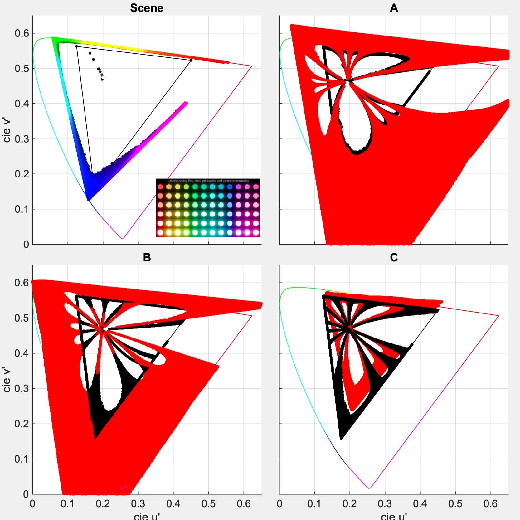
I have one question to @KevinJW if you don´t mind. You hinted at an issue with the render below because of the missing “triangle” in the plot. Could you expand on that ? Am I missing a color/column ? Anything I could improve ?
Yes it is simply the missing colour samples near the red primary moving towards magenta, which means the behaviour of the candidates is ‘missing’ - we can probably assume that a similar pattern will occur, but the extent of the ‘petal’/‘dragon fly wing’ shape isn’t measurable by the image.
As an example Candidate A might make you think the end is somewhere near 0.8, 0.5, but that would be a guess.
With candidate B it visually looks more like a straight triangle shape, etc etc.
As the missing parts are in the scene linear image I don’t believe it is candidate specific (I’m assuming it is missing those values and not a graphing artefact)
If I was guessing it is probably related to the fact that the Red/left side of the image doesn’t wrap round to the far side on the right so those colours don’t blend in the same way the others do. this is possibly visible if you were to try tile the image horizontally
If that is the case then adding an extra column of the ‘dots’ on each side of the image during the render and then cropping should result in a ‘tillable’ image and fill in the blanks.
To be specific I mean adding a red column on the right hand side and a full red, half blue column on the left. (Added the sentence)
Isn’t it simply that the blends between the colours of the spheres (which presumably have a single chromaticity) are created by the overlapping glows. But since the red spheres are at the far left, and the magenta at the far right, their glows do not overlap.
To create similar overlapping glows, it would be necessary to recreate the image with a duplicate set of magenta spheres just out of frame on the left, and duplicate red spheres just out of frame on the right.