I have no answer to what people want to use pure 2.2 gamma for. However, in the video games industry, we would not think about using anything else than the sRGB curve for SDR so I added it to ACES 2 in my own implementation and only kept that and PQ with variable max nits.
1 Like
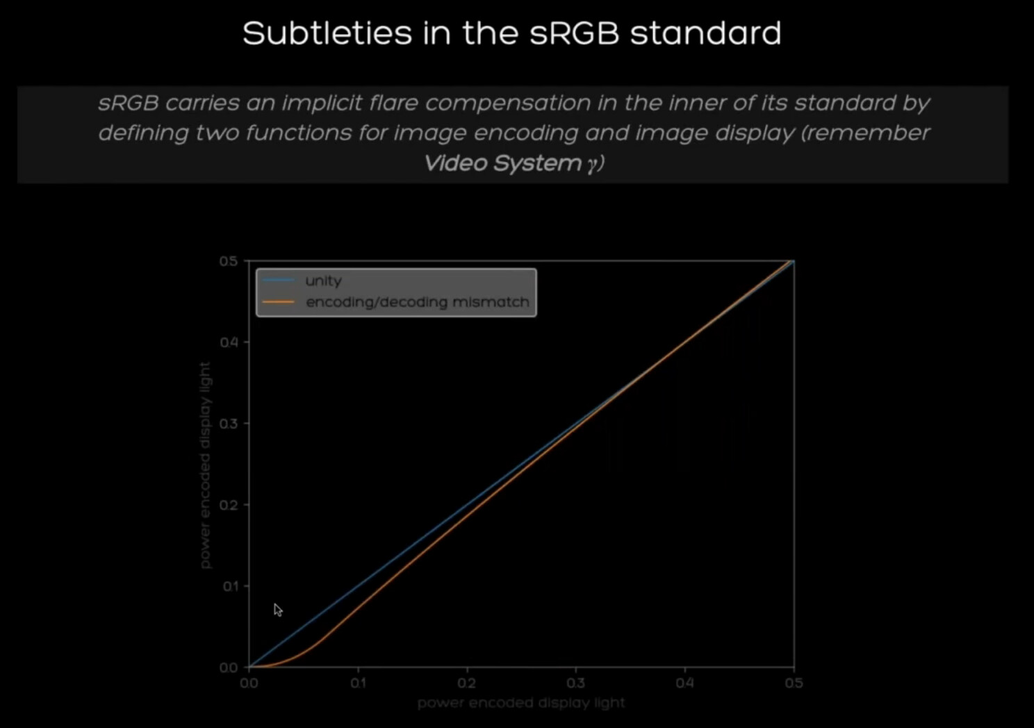
sRGB encoded images have linear segment near black (that comes from the sRGB encoding) for reasons like better math (?) and, if I get it right, for flare compensation, which is there, if I get it right again, for better visual appearance on a display that has low brightness, narrow field of view and many other differences from the real world. So when sRGB encoded image is displayed on a pure gamma display, the resulting image has an intentional mismatch, most noticeable in the shadows looking intentionally darker.
ACES DRT already has flare compensation as a part of its tone mapping. And that formed image should than be sent from the monitor as it is to our eyes. So the tone-mapped image is encoded using a curve that is inverse of a display. In case of Rec709 ODT (bad naming though) - it’s gamma 2.4. In case DCI ODT - it’s gamma 2.6. Or to say more precise 1/2.4 and 1/2.6.
And in case of sRGB EOTF displays sRGB ODT encodes this tone-mapped (and flare-compensated image) with the inverse sRGB EOTF encoding. But in reality most of the displays have and, based on what I’ve read from Steve Shaw from Light Illusion, have always had pure gamma EOTF instead of sRGB. So in case of using sRGB ODT we end up with double flare compensation, that comes from tone-mapping and sRGB encoding together.
And even legacy sRGB encoded content looks wrong on sRGB EOTF displays, because the intentional darkening of the shadows is canceled, resulting in 1:1 representation of the scene linear light (within the limitations of a display of course).
The argument, why it is intentional is the example with Rec709 encoding curve and displaying it on pure gamma 2.4 displays.
But here is another thing that makes it even more complicated.
In case of BT1886 calibration of a 1000:1 contrast ratio display, the EOTF of this display becomes almost identical (or even identical?) to the actual sRGB EOTF. And all IPS displays are only capable of from 700:1 to 1500:1 contrast ratio. Well, until the very new IPS black technology. But still it only offers 2000:1. So my point of view is that BT1886 calibration is pure evil ![]() and only makes sense with displays with contrast ratio about 10000:1 maybe. In practice, even with 4000:1 display BT1886 calibration gives a noticeably low contrasty image. But luckily, this has nothing to do with ACES, so no need for another holy war
and only makes sense with displays with contrast ratio about 10000:1 maybe. In practice, even with 4000:1 display BT1886 calibration gives a noticeably low contrasty image. But luckily, this has nothing to do with ACES, so no need for another holy war ![]()
Where is the idea that the linear segment introduced for flare compensation coming from? Its main purpose is to improve precision and invertibility at low values. I would be curious to read any reference stating that it is for flare compensation as it is typically not how you do it. There is actually an alternative sRGB curve that was designed for that:

That the system Opto-Optical Transfer Function (OOTF) is not linear to compensate for flare and viewing conditions is however true but this is something that you would find with BT.709 & sRGB or BT.709 & BT.1886.
Cheers,
Thomas
3 Likes

Flare affects the entire image, we see it more in the shadows because our sensitivity to brightness follows a cubic root roughly, see Fechner and Weber’s Laws. Consider for example some ambiant reflections on a display or inside camera optical block, there is no process that makes them only selectively appear onto the darker part of the emitted image or incident light from the scene. Now we deal with it globally, as an average component because it is much easier but it is of course more subtle than that.
please see iec61966-2-1
Section 4.1 Reference image display system characteristics:
The reference image display system is a computer controlled cathode-ray tube display and shall be as follows.
- Display luminance level: 80 cd/m2
- Display white point: x = 0,312 7, y = 0,329 0 (D65)
- Display model offset (R, G and B): 0,0
- Display input/output characteristic (R, G, and B): 2,2
and then
Setion 5.1 Encoding transformations Introduction:
The encoding transformations between CIE 1931 XYZ values and 8-bit RGB values provide unambiguous methods for representing optimum image colorimetry when viewed on the reference display in the reference viewing conditions by the reference observer. The CIE 1931 XYZ values are scaled from 0,0 to 1,0, not 0,0 to 100,0. These non-linear sR′G′B′ values represent the appearance of the image as displayed on the reference display in the reference viewing condition. The sRGB tristimulus values are linear combinations of the CIE 1931 XYZ values as measured on the faceplate of the display, which assumes the absence of any significant veiling glare. One impact of this encoding specification is the creation of a mismatch between theoretical reference display tristimulus values and those generated from the encoding implementation. The advantages of optimising encoding outweigh the disadvantages of this mismatch. A linear portion of the transfer function of the dark-end signal is integrated into the encoding specification to optimise encoding implementations. Recommended treatments for both veiling glare and viewing conditions are provided in annexes D and E.
It does not matter so much to me what people say they might have meant in the sRGB standard.
It is very unambigoiusly specified how the sRGB should be implemented.
The pure 2.2 power law is numerically unstable around zero, especially in 8bit. So they looked for an encoding method which handled multiple linear to none linear transforms and back without breaking the image. The slight mismatch to the Display Chararateristics was then just accepted as a better of two compromises. Again see here:
The advantages of optimising encoding outweigh the disadvantages of this mismatch.
To me this is clear enough.
Nowadys we do not use 8 bit processing anymore so the compound function is not needed anymore.
Also we have better methods (DRTs) to introduce flare/glare compensation
I hope this helps
Daniele
4 Likes
I think there may be a misinterpretation going on here …
@daniele is correct to point out that there’s a purposeful mismatch in the video camera encoding function and the traditional video display EOTF which compensates for flare in the captured images. Likewise, a mismatch exists when using the sRGB EOTF to display video images, which also compensates for flare.
However, the sRGB encoding function is used to encode display light as code values rather than scene light. Given the sRGB encoding function is the exact inverse of the sRGB EOTF, that means the display code values exactly tell you the display light that will be produce by an sRGB encoded image.
The compatibility of both the video display EOTF and the sRGB EOTF with rec.709 camera encoded images is due to the fact the viewing conditions and display minimum and maximum luminances were different between video displays and video viewing environments and computer monitors and office viewing environments at the time the sRGB engineering work was done.
See below from Giorgianni and Madeen
NIFRGB values, which were used in the FlashPix format, and the identical sRGB values specify color in terms of 8-bit RGB code values. The color represented by a set of NIFRGB/sRGB values is that which would be formed if those code values were input to a specified reference monitor and if the resulting color stimulus produced by the monitor were viewed according to a specified set of encoding reference viewing conditions (Table G.5).
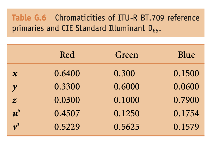
The reference monitor is representative of those used on the majority of personal computers. It is defined in terms of a set of reference primaries and a characteristic curve relating nonlinear input signals to output relative intensities. The reference primaries are those defined in Recommendation ITU-R BT.709. The chromaticity coordinates of those primaries are given in Table G.6.
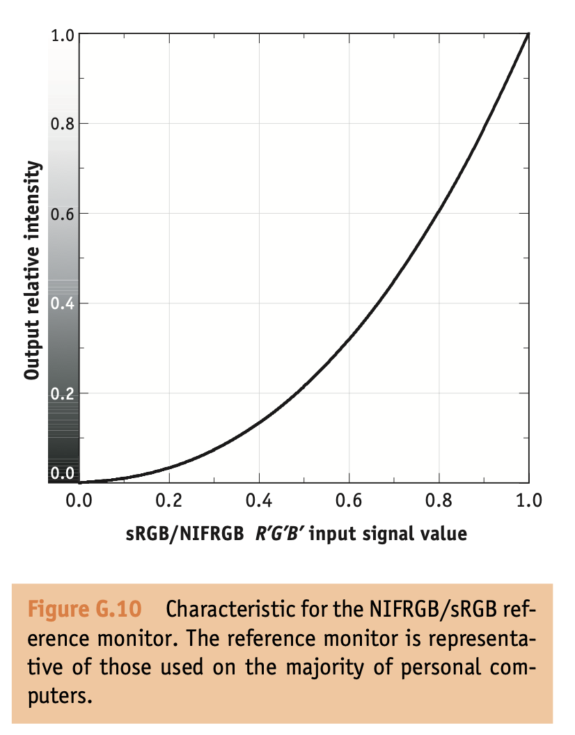
The grayscale characteristic for the reference monitor (Figure G.10) was designed to meet three criteria. First, because NIFRGB and sRGB code values are meant to be used directly as monitor code values, the characteristic had to be consistent with the characteristics of actual monitors. Second, the characteristic had to be such that its use produced images in which the visual effects of quantization were minimal. Third, for use in transformations, the characteristic had to have good mathematical reversibility.
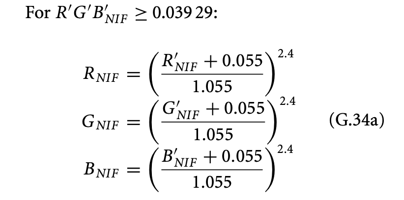
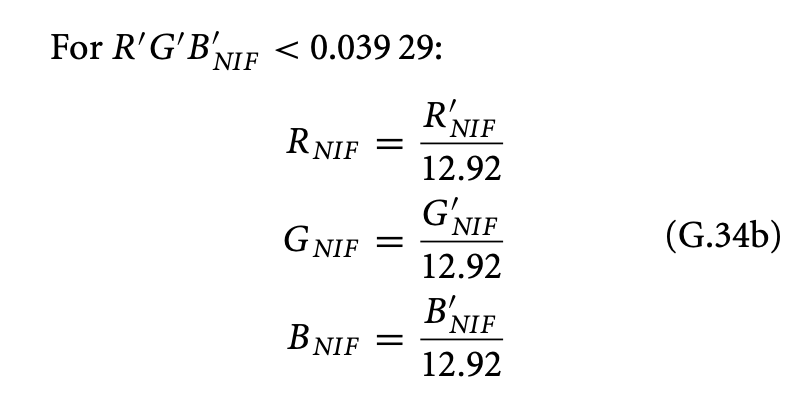
The monitor characteristic is defined by the following equations relating nonlinear input signal values, R′G′B′NIF , to output relative intensity values, RGBNIF.

I fully recognize that this may not be the way people are using sRGB in practice and it’s clear there was lots of confusion around sRGB right from the start. Frankly, it doesn’t matter as next to no one uses a computer monitor in the intended environment, at the 80nit max luminance originally specified. I’m just trying to bring the historical context I’ve managed to collect, directly from the people who engineered sRGB, as not to keep propagating urban legends about why certain characteristics of the system are what they are.
1 Like
If we quote something we should stick to the actual iso standard.
There are many ambiguous sources out there and we should let a political fight of the past confuse the present and the future.
2 Likes
I think this is the real problem. It almost seems that a part of the authors try to override what was agreed upon in the standard. Or why do we need NIFRGB as stated separately.
I am not quoting urban legends but the standard itself.
Just for context, @Alexander_Forsythe comment is not a reply to my post, we both send a reply almost at the same time.
To be more specific (hopefully, we can end the debate if we introduce the elephant in the room)
This is exactly where alternative sources like you have posted diverge from the original standard.
It is even worse because some of the alternative publications may come from some of the original authors of the ISO standard, which gives those sources some credibility.
Another example of an explicitly misleading source:
or
But then you look here:
https://www.w3.org/Graphics/Color/sRGB.html
(checkout CRT Gamma)
It is just confusing from nowadays point of view.
The ultimate facts or authority can only come from the standard itself. Otherwise, we have different definitions of facts, and this is shaky ground for an objective discussion and the root of all this debate.
I don’t want to sound disrespectful, but the authors publishing alternative definitions only confuse the industry. If you are unhappy with a standard, try to get an erratum through and fix the standard, or make a new standard but don’t push your agenda resuing the same name through alternative channels. That only leads to confusion for generations to come.
Basically, we are continuing a debate from the 90ths…
The original authors seem to have agreed not to agree.
Displays, Pipelines and Cameras have changed a lot since then.
So maybe we need to abandon the term sRGB completely. Or we need to be more precise.
If I talk about sRGB I mean IEC 61966-2-1 sRGB.
I hope this helps.
Daniele
2 Likes
So, I see it like that now. And sometimes it feels a bit contradictive. But as always, please feel free to correct me.
• Rec709 encoding function (published in 1993) has linear segment near black to deal with noise, that would be stretched too much by encoding with power function. It isn’t there for flare compensation, but affects the image in a way more noticeable way, than simple gamma mismatch.
• If we just tone map the highlights of a Rec709 encoded image, it immediately looks similar to different tone mapping curves from camera LUTs. Is it a happy coincidence? Also DaVinci tone-mapping looks almost identical to Rec709 encoding in the shadows.
• Rec709 encoded image should be displayed on a pure 2.35 gamma display.
• sRGB encoding function (published in 1996) has the same formula as Rec709 but with different numbers, and linear segment near black this time is there to avoid near-infinite multiplication in the shadows by a power function. Again, it’s there not as a part of an image rendering, but still affects the image in a significant way (in case of displaying it on a pure gamma display, just like with the image path in video).
• sRGB should be displayed on a pure gamma display (which is written in the standard).
• ICC color management of an operating system assumes that if not specified, the image is sRGB encoded and the display is also have sRGB piece-wise EOTF, and because of that, ICC color management, based on its wrong assumption about EOTF of the display, does the right thing, sending unaltered image to a pure gamma display. But if someone decides to calibrate their display using ICC for that, now ICC knows the actual EOTF of the display, and whatever the EOTF is, ICC alters the image in a way to display it 1 to 1 to linear data, cancelling the intentional mismatch introduced by the encoding.
• There is another reading of sRGB standard, that claims, the sRGB encoded image should be displayed 1 to 1, completely cancelling the encoding by a display sRGB EOTF.
• Most of the sRGB encoded content had been produced on pure gamma displays, especially in the earlier years.
• Modern approach is to actually encode the image to a real EOTF of a display. And all the tone-mapping things are done at the previous stage. But if no tone-mapping (including toe setting in the shadows) was done, then the image, that is displayed 1 to 1 to linear data, looks flat.
What a beautiful world of standards!
Sorry if the NIGRGB reference is confusing. The quote I provided is from a larger section about the encoding methods of FlashPix. The NIFRGB (new image format) terminology was the term used for the standardized computer display in that system.
I think being precise is key, so as @jack.holm stated earlier, we shouldn’t refer to displays with a max luminance of anything other than 80 nits in an average surround as sRGB
So we should remove the sRGB ODT then?
2 Likes
I’d be fine with renaming for clarity
• Most of the sRGB encoded content had been produced on pure gamma displays, especially in the earlier years.
I feel like most sRGB encoded content has been produced in an ICC color managed environment which has produced an end-to-end system gamma of 1.0 like you mentioned above. sRGB encoding/decoding to PCS (Profile Connection Space) to Display Color Space (determined by an ICC profile)
If we say “most”, we’d be suggesting the vast majority of installations?
In that case, the statement above is false.
Defaults shipped with Windows and Apple indeed abide 100% to the letter of the IEC specification. Specifically, given that the default encodings stipulate the two part transfer function on the display side, including in default factory shipped characterizations on Apple devices last I looked, this leads to:
- Encoding state two part OETF.
- ICC / ColorSync checks EOTF description, which is incorrectly identified as the two part, and leaves the encoding “as is”.
- The actual EOTF, being a pure 2.2 exponent, is applied to the code values.
That means I believe, by default, all installations will conform to the standard.
1 Like
Sadly it appears not to be that simple.
I just measured the “Liquid Retina XDR Display” of my 14" M2 MacBook Pro in a couple of the out-of-the-box preset profiles.
Using the default Apple XDR Display (P3-1600 nits) profile, the EOTF is indeed a close match to a pure 2.2 power curve for an Apple Display P3 tagged buffer.
However when set to the HDR Video (P3-ST 2084) profile, it appears that an Apple Display P3 tagged buffer is converted to ST.2084 using the piecewise sRGB curve.
So the HDR “reference mode” acts like a PQ display emulating the piecewise sRGB EOTF, but in “normal” mode it matches the behaviour of older Apple displays, where an image with an sRGB profile has its pixel values left “as is” and sent to a display with a pure 2.2 exponent EOTF.
MBP14_XDR_Display_plots.pdf (38.9 KB)
1 Like
Nifty comparison!
I am not sure what other option is feasible given it is a totally different encoding specification?
I don’t think much of this matters; our visual cognition systems appear to have no agency to identify discrete time magnitudes. On a practical level, it becomes mostly an exercise in number fornicating, which I suppose is popular from what I’ve seen.
The only reason it holds a degree of value to discuss is broadly what Daniele has pointed out; it is ahistorical to debate what is outlined at several places within the specification, rather rigidly, as well as logically sound.
It is also worth considering that the explicit management chain, such as is present in the ICC protocol principles, has never addressed the notion of picture quality constancy beyond that of vendor supplied secret sauce “Perceptual” and “Saturation” “rendering” intents, and neither of those address surrounding field articulation. In fact, spatiotemporal field articulation of the surrounding environment remains solely a concern of an implicit management chain.
Remove or rename?
The name is purposely ODT.Academy.sRGB_100nits_dim.ctl and not ODT.Academy.sRGB.ctl to denote that it is not sRGB as per-the-standard and the description is rather clear about it:
// <ACEStransformID>urn:ampas:aces:transformId:v1.5:ODT.Academy.RGBmonitor_100nits_dim.a1.0.3</ACEStransformID>
// <ACESuserName>ACES 1.0 Output - sRGB</ACESuserName>

//
// Output Device Transform - RGB computer monitor
//

//
// Summary :
//  This transform is intended for mapping OCES onto a desktop computer monitor
//  typical of those used in motion picture visual effects production. These
//  monitors may occasionally be referred to as "sRGB" displays, however, the
//  monitor for which this transform is designed does not exactly match the
//  specifications in IEC 61966-2-1:1999.
//
//  The assumed observer adapted white is D65, and the viewing environment is
//  that of a dim surround.
//
//  The monitor specified is intended to be more typical of those found in
//  visual effects production.
//
// Device Primaries :
//  Primaries are those specified in Rec. ITU-R BT.709
//  CIE 1931 chromaticities:  x         y         Y
//              Red:          0.64      0.33
//              Green:        0.3       0.6
//              Blue:         0.15      0.06
//              White:        0.3127    0.329     100 cd/m^2
//
// Display EOTF :
//  The reference electro-optical transfer function specified in
//  IEC 61966-2-1:1999.
//  Note: This EOTF is *NOT* gamma 2.2
//
// Signal Range:
//    This transform outputs full range code values.
//
// Assumed observer adapted white point:
//         CIE 1931 chromaticities:    x            y
//                                     0.3127       0.329
//
// Viewing Environment:
//   This ODT has a compensation for viewing environment variables more typical
//   of those associated with video mastering.
//
I just noted that the ACEStransformID was kept as RGB: urn:ampas:aces:transformId:v1.5:ODT.Academy.RGBmonitor_100nits_dim.a1.0.3
Cheers,
Thomas