A few Color Appearance experiments

This is not a thread to debate whether Color Appearance Models are the best solution for a DRT, or how well they model the complexity of the human visual system. There is already a “Debating CAMs” thread.

CAMs are not perfect, and as Troy has demonstrated, almost certainly a poor choice to paint in or composite with.

This thread is primarily to demonstrate what CAM are pretty good at and what (mostly) they have been designed to be good at:

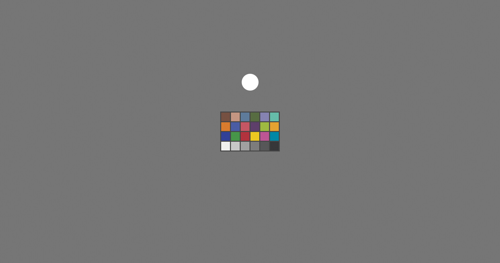
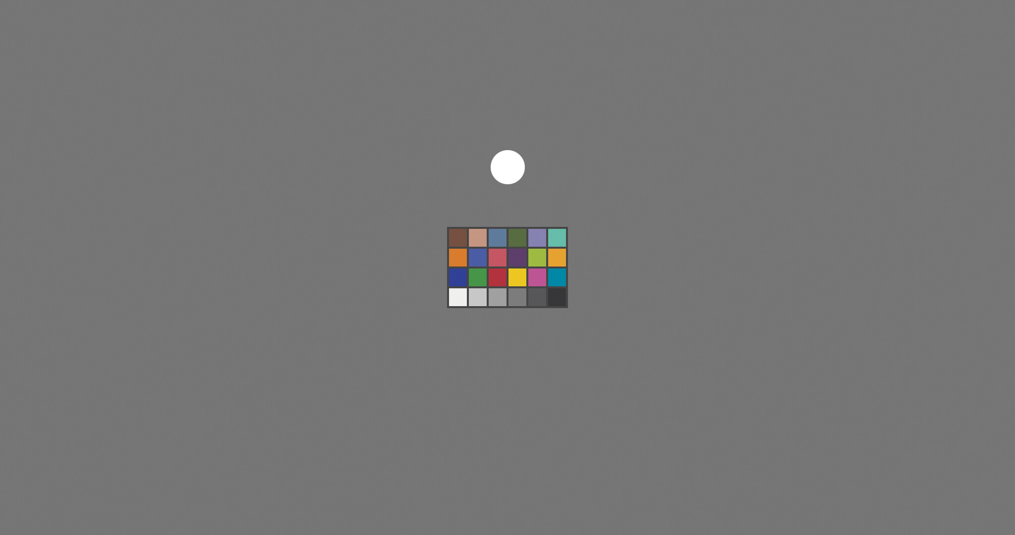
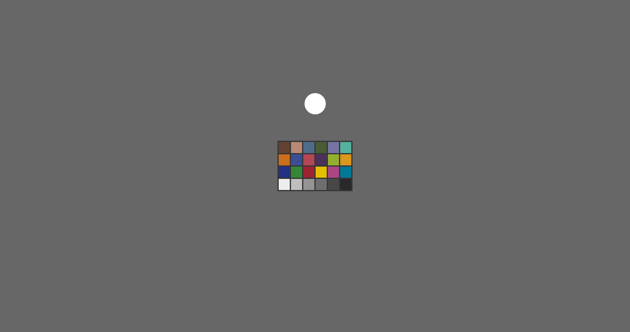
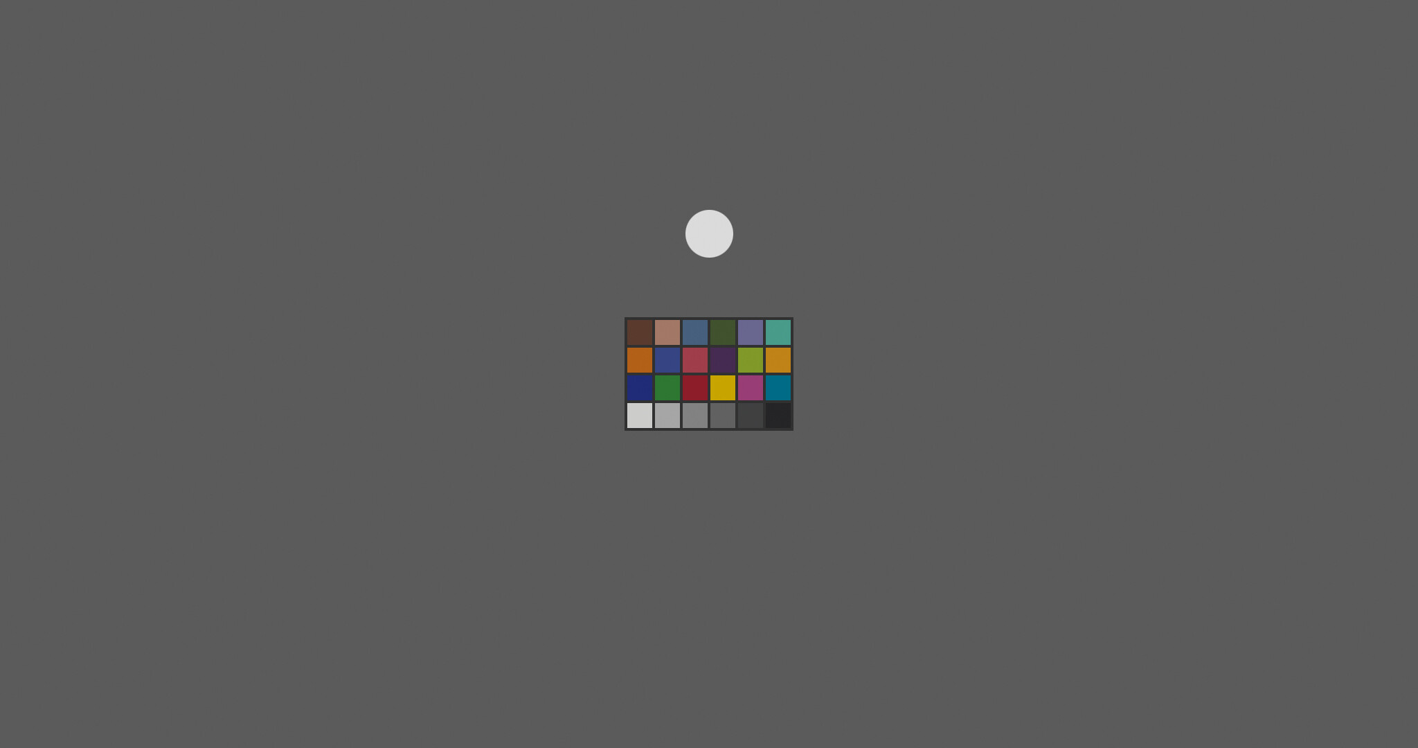
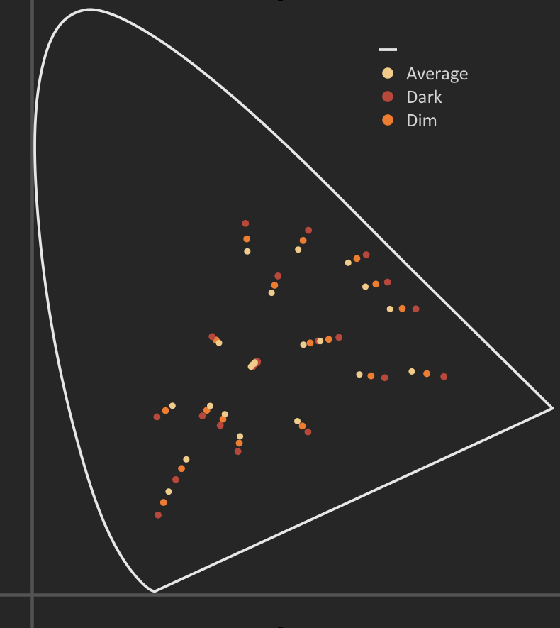
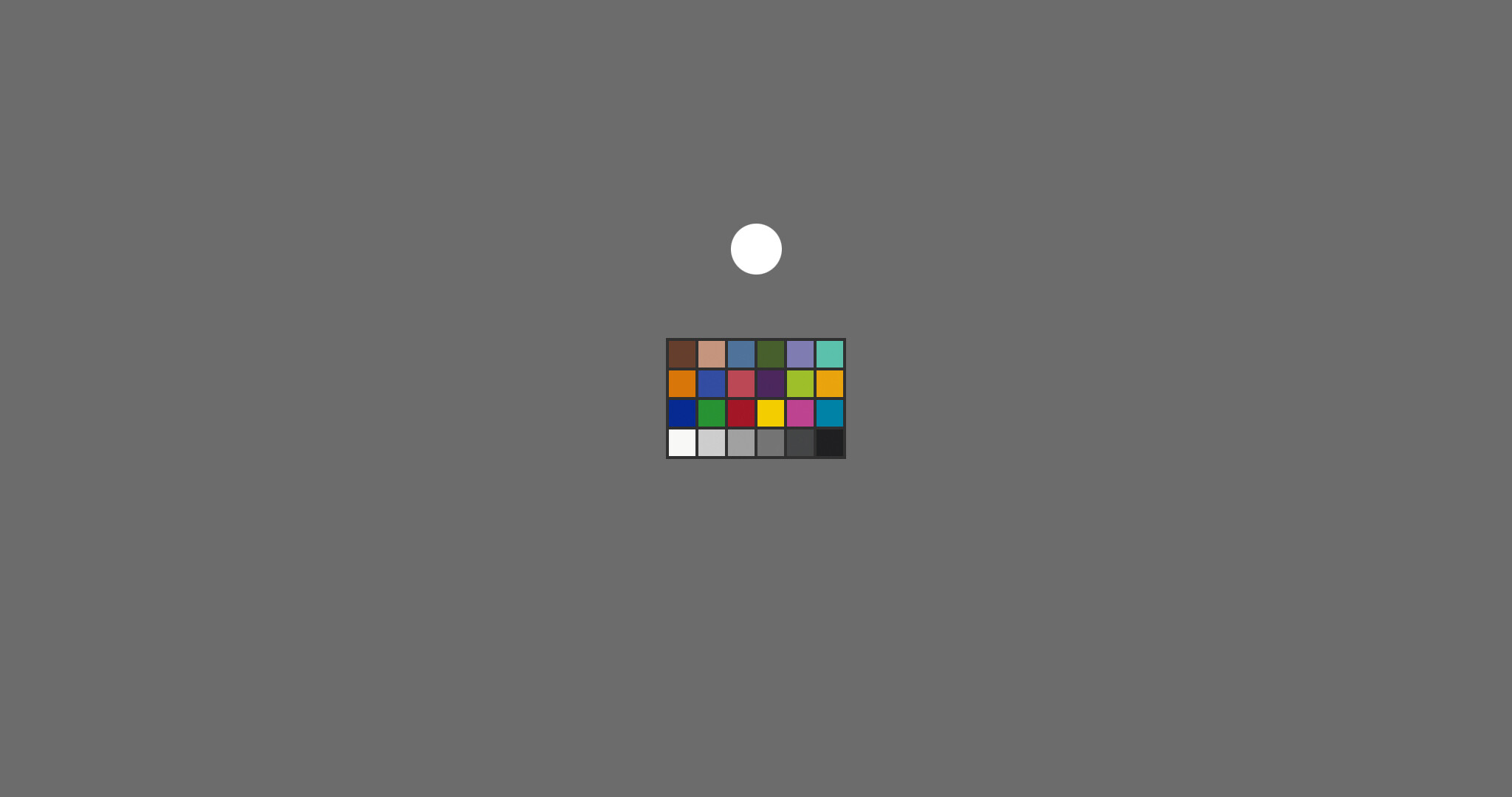
To predict the appearance of images/color stimulus under different viewing conditions and/or different levels of illumination.

It is the (statistical) success in that area that made me wonder why there has been some difficulty finding an easy/simple way to match the HDR and SDR output. This seems like a task for which CAM based DRT should be the perfect tool.

The think the really big and difficult question is, “How should/could the image look?”.

or “Should the HDR image match the appearance or the SDR image”

“Should the HDR image look “better”, brighter, more colorful than the SDR image”

These questions will continue to be a challenge, and how they are answered may determine how the features available in a CAM model are used.

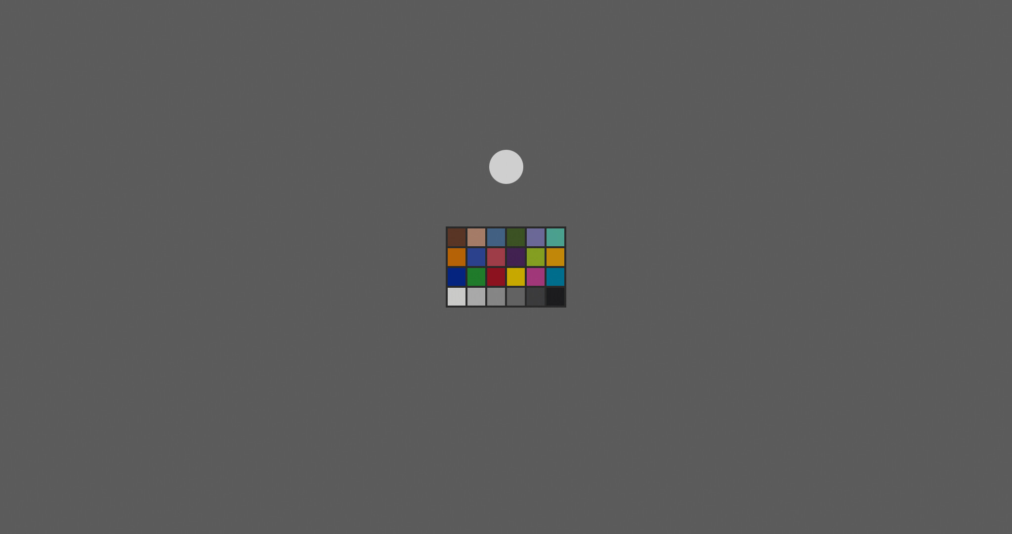
The following tests may be redundant and uninteresting to those already familiar with CAM models, and their development, but but the systematic approach to a familiar image, should at least provide some specificity or footholds in the sometimes confusing or circular discussion regarding the behavior and parameters in and out of the models.

Please feel free to ask any questions or point out errors regarding the procedures I used to do these experiments, but please hold back any snap judgement whether these experiments are of any value (for at least a few hours!).

I will also try and reserve my own judgement until a few posts are made, but I do think the images quickly offer some insight into the different paths/approaches that may be have been overlooked or require further attention in the current CAMDRT.

I have designed these to be downloaded and viewed and compared at full screen, and could provide a link with all of them if there is demand, but also a few animations for quick comparisons where it could be useful.

Christopher

1 Like

All the examples I post will use this image.

It is a colorchecker chart taken directly from the ACES spec and along the right edge of the familar “synthetic image” from the ACES image archive.

The surround is ACES Linear 0.18 and the white disco above the chart is ACES Linear 1.0.

I have provided a massive field of grey so that these images can potentially provide a real color appearance demonstration and even simulate HDR output on an SDR display within the very limited range of a normally exposed colorchecker.

All the images are labeled and should display correctly in sRGB (whatever that means!)

This first image is a direct transform from ACES to sRGB and could function as a baseline/groundtruth for an unrendered or un-transformed image.

This image is probably makes one of the most important points of this demonstration.

This was an ACES Linear image with a D60 whitepoint transformed through a stock CAM using “Average” surround parameters and output to D65 with “Average” surround parameters.

The result should be no visible change compared with the direct ACES to sRGB transform.

This may seem redundant, but it demonstrates that CAMS can do no “harm” or have any effect at all under certain settings.

Now begins the real demonstration of CAMs

Here is the same image with D60 and Average surround in and D65 “Dim” surround out.

Here is D60 Average surround in D65 “Dark” surround out

Here is an animation comparing the output under different surround conditions

Color_Checker_Surround_Compare

The next three images are are the same as the last three (Average in and Average,Dim and Dark out) except I fixed the 0.18 grey to match ACES 1.2/ACES 035 values.

Color_Checker_D60_Average_in_D65_Average_Grey_Match_out

Color_Checker_D60_Average_in_D65_DimGrey_Match_out

Color_Checker_D60_Average_in_D65_Dark_Grey_Match_out

Here is an animated comparison of just the Dim surround

Color_Checker_Mid_Compare

This is effectively acts as a kind of comparison of SDR and HDR images.

The grey is a familiar SDR target value ( Y =0.10ish) and the Diffuse white Value is a common target for HDR output (Y=100)

Even though this is only an “ideal” color appearance transform, from one viewing condition to another and not necessarily a tasteful render from linear to display, it should still be worth considering because these basic transforms (or their precursors) have probably been used in the optimization or evaluation of every imaging system (Film, Television, Printing Industry) since the 1960’s.

Now for a little analysis.

Keep in mind all JMH values are exactly the same for every image!

Only the output surround conditions and white point where changed.

The resulting XYZ values show increased saturation/chroma as the viewing conditions go from Average to Dark

Here is a comparison of the Dim surround at two different output white points as above

This little or no change on CIE plot, even though the colors are increasing in luminance.

At this point I want to offer a little commentary that I will return to again, and hope to bring up in future discussions.

Based on this very limited experiment using a standard color appearance model, saturation/chroma should not change (very much) with increased luminance, (SDR to HDR), but only with increased slope/contrast associated with changing viewing conditions.

I am not referring to values within the model, but only measurable increase on CIE Yxy plot.

It is likely that the description colourfulness or Hunt effect does come along for the ride with increased luminance but it should not appear as more “saturated” just brighter.

This of course is only if the intention is a close appearance match between SDR and HDR.

Almost all current HDR transforms take some advantage of the increased luminance/dynamic range with an increase in the slope relative to SDR and therefore should expect/require an increase in saturation.

How much that change should be is really the question.

The next two images are a bit of a proof of concept for this experiment.

Here is the standard output from ACES 1.2 SDR

Here is the output from ACES 1.2 HDR at 1000 nits and diffuse white of 100

These are a pretty close appearance match, with primarily the sense of increased luminance.

These are directly from ACES AP0 using OCIO into sRGB, no CAM was used.

Here is a CAM transform of ACES 1.2 HDR transformed in a CAM to match the grey point of ACES SDR.

and an animation for easy comparison.

A pretty good (not perfect) match with only change in white point though the CAM.

Color_Checker_ACES_1pt2_HDR_to-SDR_Match

Whether a CAM was used to guide or evaluate the ACES 1.0 HDR transform or not (hard to imagine it wasn’t), it demonstrates that using only a single parameter in the output (whitepoint) a stock Color Appearance model can be used for very basic transform of an output from HDR to SDR and vice versa.

So far the only evaluation has been visual and a CIE diagram to show the changes with various output surround and whitepoint conditions.

All JMh values have been identical, so no comparison was possible.

Only if I feed the output back into the model and compare the difference in JMh that a comparison is possible.

I used a standard CAM16 model so the values may not perfectly match another model but the relationships should be similar.

All images used D65 input with average surround conditions.

I believe this the the appropriate surround condition to evaluate the output especially if comparing that output to the original linear ACES input.

Here is a graph of the changes in J with change in viewing conditions

As expected, there is no change to the J with from ACES average input to average output conditions.

The changes to J with Dim and Dark output conditions can be very well fit with only a power function.

This graph shows the changes from each condition with a diffuse white watch vs the same condition with a match to ACES 1.2 mid grey output.

There is very little change to the output for dark since the 0.18 grey is already an almost a perfect fit to the target output for ACES 1.2. Almost certainly not a coincidence.

These changes in J are effectively the same as a change in target display luminance and can be fit very well with a simple slope and offset.

Here is a comparison of J between ACES 1.2 SDR output and the standard output from a CAM transform from Average to Dark viewing conditions. White whitepoint adjusted to match 0.18 grey.

As should be expected the ACES 1.2 (and all ACES output transforms to date) the values match very closely the ideal tonal scale for a Dark surround condition, plus the required roll off to fit values above 1.0 onto SDR displays, and maybe a little slope in shadow region to offset viewing flare.

This is probably no news to anyone who is has been involved in the development of ACES at any point.

The next post may start to get more interesting….

I have already shown that there is an increase in going from Average to Dim and Dark surround output.

But when those same outputs are put back into a CAM16 model the M values do not fit a trend very well and the Dim output event shows a decrease in M from the Scene M values even though the output
images and CIE diagram show more saturation.

This is likely due to the darker white point used to match the mid grey to ACES SDR target and the Dim needing a darker white point to match.

That is not a problem for M values within the model, they can be whatever they need to be, except that those values result in very little change on CIE diagram.

Here is a comparison of M values for Dark surround and ACES 1.2 SDR output.

It shows some ColorChecker M above the scene and some below with not great fit to any line but averaging about the same as the ACES scene M values.

Here is one of the most curious finding so far with this experiment.

There is a nearly perfect straight line fit from scene to viewing conditions with the “s” component of CAM16.

both Dim and Dark are slightly increases in slope.

A slope of roughly 1.1x for Dark and 1.046x for Dim

This will be my last post for today since 20 is plenty for one day.

It is a comparison of CAM16 “s” attribute/component from ACES scene to ACES 1.2 output.

It does not show a very good fit to any line like the ideal dark surround does, but that is to be expected since it is a mostly an RGB transforms with some extra hue dependant and saturation tweaks.

But overall the best fit to change in “s” is pretty close to the ideal dark surround output, and the ACES 1.2 HDR fit is almost a perfect match (dashed bright red line) to the ideal Dark surround change in “s”.

ACES 1.2 SDR

ACES 1.2 HDR 1000nits

I want to repeat, this is so far just curious, and in no way a solution to the multi faceted problems that are required for the full CAMDRT transform to be practical.

None of the stock CAM transforms take into account a pleasing rendering from scene values or highlight roll off and path to white for SDR display, and certainly gives no guidance for the essential gamut mapping to various real world displays.

What I would suggest that this experiment could show is that if the output display was a wide gamut 10000 nit display and the scene had colors that more or less fit in that gamut you could probably get away with something as simple as a single power function and a slope could be used to transform J to fit any Viewing condition and target diffuse white or middle grey and another slope for corresponding saturation increase required for the viewing conditions. I am not sure any roll off would be needed and probably no path to white if the scene was limited to ACES cct. The colors would roughly appear colormetric but not necessarily pleasing.
I am sure this kind of logic for a display transform is/was a common approach and at least partly why such bright displays have been developed in the first place. (I haven’t thought too hard on it, but is this maybe how stock ZCAM is intended to be used?)

I don’t suggest this approach, it is only a thought experiment and/or sanity check to understand what minimal transforms are actually required when using a CAM for a DRT, so that the best possible (simple or not) transform can be designed.

I have many more experiments including images and plot comparisons of many popular outputs from different vendors and ACES 2.0 candidates on the Colorchecker with 10 stops over and 10 stops under, but for now I will stop and see if any of this is worth discussing.

Christopher

2 Likes