A single fixed Output Transform vs a choose-your-own approach

Thank you for your answer! I think ACEScc is also very important because it finally lets CDL corrections to be physically correct. And AP1 for some reason (maybe accidentally) is very good for WB from my limited tests with color checker and comparing it to different LMS spaces.
Many colorists I know think that offset over any log, and especially ACEScct is identical to RAW WB or aperture on the lens. I think, if the fact, that its is true only for ACEScc, will be mentioned somewhere, probably in the ACES documentation, it make people to use ACEScc more often.
Sorry I’m not trying to tell you what to do, I’m just a random colorist, and of course you know better what to do with ACES. I hope I don’t I say something inappropriate. I’m just trying to make the whole image pipeline better and more intuitive for all by a sort of promoting ACEScc. And my far from perfect English definitely doesn’t help me with that and makes me sound strange a bit I guess :slight_smile:

1 Like

Hello,

I currently see three topics in discussion for the OT VWG :

@KevinJW Would it be possible to upload the diagram shown at meeting#5 in this thread ? Or create another one if you prefer ? So the conversation about modularity/flexibility can happen between meetings ?

Regards,
Chris

@Thomas_Mansencal started to reproduce @KevinJW diagram on a Miro Board.

Some of @daniele 's comments have already been added (the bottom diagram I think) :

  • I would not put output rendering in the scene referred bubble.
  • I would clearly separate LMT from the rest.
  • The output rendering is the collection of processes rather than one specific box.
  • You could put the “display encoding” ( EOTF and Matrix) on each leave, to clarify that the ODT should not have anything more in it.

You can make some notes on the board to share your thoughts. Cool !

And here comes stupid question#1. :wink: During meeting#3 there was a conversation about AP0 and AP1 spaces with the following comments :

Originally AP0 was meant to be the exchange and working space.

[The rendering transform] flips between AP0 and AP1 a few times.

When you look at the CTL code for the RRT and the ODT, there are indeed several transforms :

In the RRT :

  // --- ACES to RGB rendering space --- //
    aces = clamp_f3( aces, 0., HALF_POS_INF);  // avoids saturated negative colors from becoming positive in the matrix

    float rgbPre[3] = mult_f3_f44( aces, AP0_2_AP1_MAT);

    rgbPre = clamp_f3( rgbPre, 0., HALF_MAX);

In the ODT :

// OCES to RGB rendering space
float rgbPre[3] = mult_f3_f44( oces, AP0_2_AP1_MAT);

I am wondering if those transforms are still necessary with AP1 being the working space today. I can see in the diagrams that ACES2065-1 is considered the scene-referred space. I am curious about why…

Thanks for your answers,
Chris

The AP1 to AP0 at the end of the RRT and the AP0 to AP1 at the start of the ODT will indeed cancel each other out, so are strictly redundant. Implementations may in fact not include them for efficiency, as the OCES image data between the RRT and ODT is never exposed to the user.

I think their inclusion is more conceptual for the block diagram, as the intent is that image data is in AP0 as it passes from one block to the next. But what an implementation actually does is not important, as long as it achieves the aim.

Hello, thanks Nick for the reply and I also wanted to share some updates about “my little experiment” on the Miro board.

I think we were able yesterday to move forward with a more representative diagram from Daniele’s idea. Here is my thought process (based on the two last meetings’ notes) :

  • The fork should not be at the LMT.
  • There can only be one rendering intent.
  • Display transforms should be as pure as they can be (matrix + inverted eotf).

Based on all these assumptions, the only solution I could come up with was a three-stage process.

I am clearly not the most adequate person to do that but I have time on my hands and I find the exercise particularly stimulating. :wink: Interestingly enough, there was a conversation on Slack with some very interesting points that I think are worth sharing with the VWG.

First point was about similarities between Daniele’s idea and OCIO2 :

there’s a lot of conceptual overlap between some of the stuff Daniele demonstrated and some of the OCIO-2 architecture / design. (basically, from left to right, ColorSpaces —> Looks —> ViewTransforms —> DisplayColorSpaces)

And the conversation even got to a more interesting point :

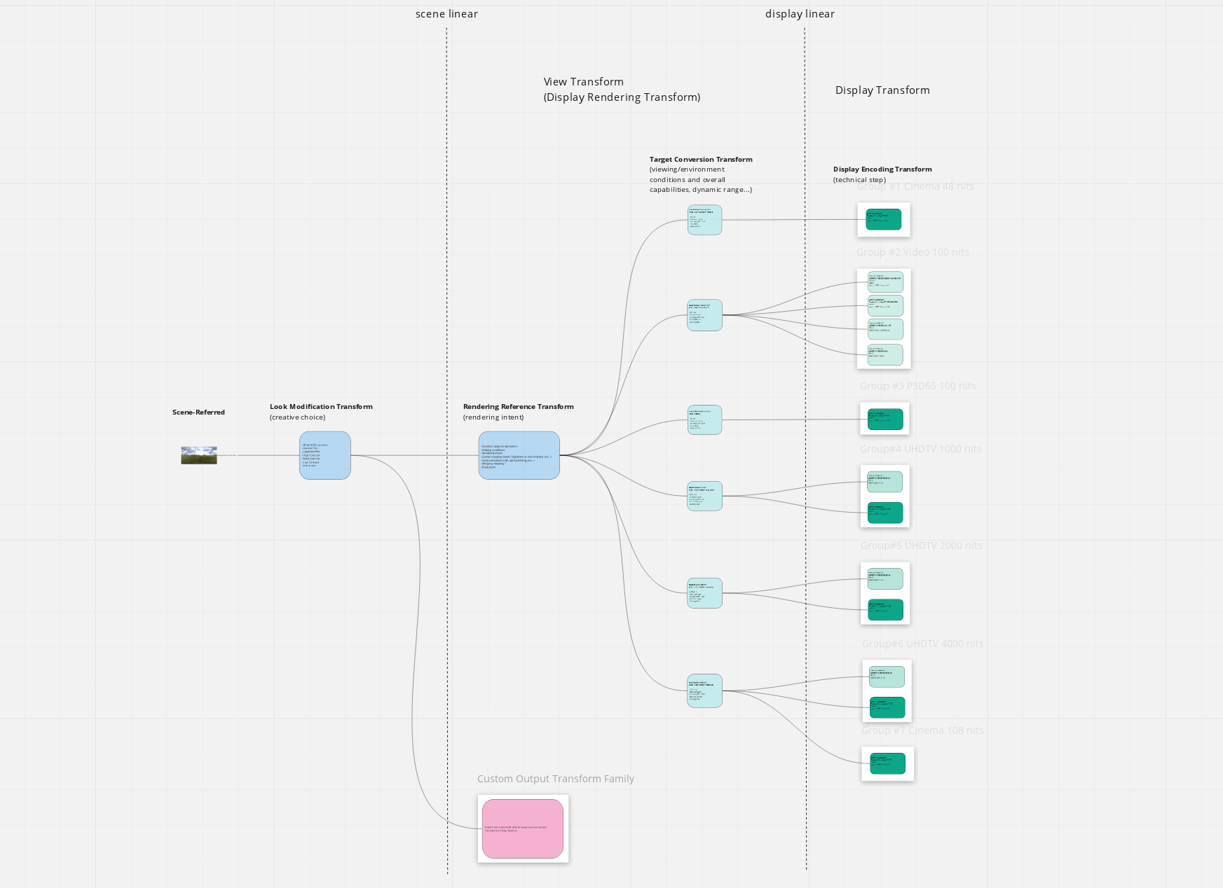
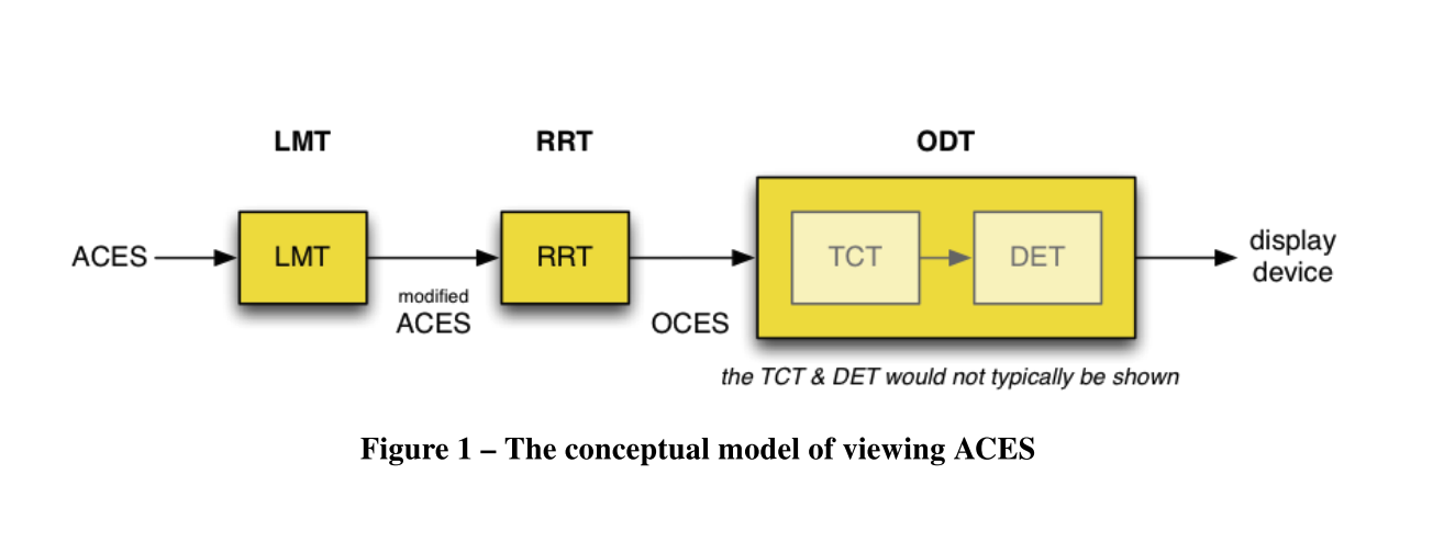
There’s a super obscure ACES technical bulletin […] — TB-2014-013 — that provides an alternate “block diagram” conceptualization. It divides the ODT into two blocks: the Target Conversion Transform (TCT) and the Display Encoding Transform (DET). The DET is the “on-the-wire” stuff (ocio DisplayColorSpaces); and the RRT + TCT make up what OCIO calls a ViewTransform (for the ACES family, in this case)

I think it is a good thing that OCIO2, ACES2 and even BaseLight go to the same direction. It makes sense to me. So I have tried to adopt this terminology on the Miro board, because it is really helping the conversation I think :

  • View Transform is made of Rendering Reference Transform (RRT) and Target Conversion Transform (TCT).
  • Display Encoding Transform (DET) is the last step of the chain.

Finally, some wise words from Daniele :

I think this abstract discussion about system overall design is important before we jump into the details of one particular implementation. Keeping it abstract at this point is key. The less you specify explicitly and the longer you stay on the mechanic side the more general your system might be. For example my proposal would also still be true if we decide at a later stage to roll in spatial or temporal processing per viewing condition.

Thanks Zach, Sean, Nick, Carol and Daniele !

Regards,
Chris

1 Like

In your version of the diagram, what is the single RRT block doing?
I think our two diagrams are almost identical but you put in a single RRT, how is this different from an LMT, if it is just a single transform?
Is it really needed then?

1 Like

Well, that’s a proper question. And this is where I’m probably confused. :wink:

Yesterday, three main steps were listed (with the OCIO comparison) :

  • Look
  • View
  • Display

I think that’s a good summary of what we’re trying to achieve. So in my head :

  • LMT is the grading/creative choice
  • RRT is the gamut/tone mapping (which is not creative for the sake of argument, it is “neutral”)
  • TCT is the viewing conditions and overall display capabilities
  • DET is just the technical encoding step

Which makes me realize I have four steps… :wink: Maybe what you’re suggesting is to merge RRT + TCT into one block and have several of them ? But then we go back to the LMT being the fork… which is not what we want, right ?

Since the idea (that I love) is to give flexibility/modularity, I understood that having the RTT as the fork would make things easier. Because you may want to keep you creative grade (LMT) while swapping the whole DRT.

Something I want to ask you about your diagram is : how the multiple output transforms from the ACES family are connected ?

Too many riddles :wink:
Chris

I see where you are coming from.
Your initial diagram focused on displays rather than on transforms.
I made yet another version of yours a bit to the right. I removed some details to not loose ourselves in the details just yet.

Thanks, that’s much appreciated. Food for thought !

Chris

The LMT is scene linear to scene linear, and the RRT is scene linear to display linear if I’m not mistaken.

Having just read through Ed’s paper (that Alex posted), I can see the value of a single RRT, and I would also keep Chris’ four steps segregated and not combine the RRT & TCT:

The RRT would provide an initial tonescale and gamut mapping and, as the name implies, is the “reference” for all other display transforms (it’s the “golden image”, despite not being actually visible; it’s purely theoretical as no current or even near-future display technology could accurately show it). This is the scene linear to display linear transform, and there is only one in this case. It needs to have established specifications for the theoretical display it is transforming to; we could propose, for example, something like 10,000nit peak, D65 white, AP1 (or maybe BT.2020) primaries, dark surround.

Transforms for “real world” displays (BT.709, Rec.2100 PQ 1k, DCIP3, etc) are based off this theoretical display, so the TCT for each of these displays is distinct, and mapping “down” (smaller gamut and/or dynamic range) from the theoretical display (display linear → display linear).

Both the RRT and TCT are potentially modular. You can exchange the single RRT for a different renderer (K1S1-esque, etc) and it would affect all outputs equally. Or you could swap out an individual TCT if desired. This would accommodate (I think it was Thomas that was proposing) a display-level LMT; except instead of an in-line LMT for a particular display, it would simply be a different TCT with the desired alterations.

Unless I’m thinking about this differently than Chris, to clarify the Miro board in Chris’ drawing the display linear line should be between the RRT and the TCT, as after the RRT you are in display linear space.

This is a nice summary of the status quo of ACES :-).

Don’t get me wrong, this is conceptually all understandable, and this theory harmonise digital and film pipelines quite well, but I am wondering if that concept of RRT really brings us something in practice?
And there are successful pipelines out there that work nicely without it.

I think I finally understood what you meant ! When you said I am focusing on displays rather than transforms. I re-watched meeting#8 recording and realized that I misunderstood what you said about the fork…

It only took me six days to figure something out ! Yay !

So, beware, I am going to trash my Miro board (but we have the screenshot if we ever need to come back to the RRT+TCT version).

Chris

If I’m understanding you correctly, the question is whether there is one “master” rendering, or whether there are multiple renderings, defined by some type of groupings (by viewing conditions or display capabilities)? Maybe this is alternately stated as there being an “intermediate” transform (in the case of a single RRT) versus sets of direct scene to viewing condition (display) transforms. I think that’s what you’re getting at?

For ease of description I’m going to describe this as two-stage (RRT to TCT) vs single stage (scene to viewing condition)

I’m going to make a start at a pros/cons list to help (at least me) think through this:

Two-stage pros:

  • Single core renderer is easy to update/revise (ACES 2.1, 2.2, etc)
  • Single core renderer is easy to swap for alternate renderings
  • Specific displays or viewing conditions can be added (TCT’s) without re-analyzing/re-creating a rendering algorithm

Two-stage cons:

  • Two step process is potentially less cleanly invertible
  • Requires better metadata tracking of the RRT version and TCT versions
  • Cannot take advantage of a potential future display that has greater capabilities than the “reference”/theoretical display of the RRT

Single-stage pros:

  • A more “pure” transform from scene values to display values
  • Likely more easily invertible
  • Can add new viewing conditions at any time

Single-stage cons:

  • Multiple groups of renderings have to be created and maintained for every rendering “look”
  • Rendering sets may be incomplete if developed for specific uses

I’m sure there are more things to add to the list, but that’s what I’ve got off the top of my head for now.

EDIT: Daniele, you also at one point talked about a “sliding scale” rendering where there is for instance a 100nit render and a 5,000nit render, and anything required in-between is calculated from a merger of these renders. Is there a way that fits into one or both of these scenarios, or is this a third type of approach?

As some whose happy that ACES is simple to use and gives pretty pictures out of the box (most of the time) I may be misunderstanding some of the intentions of having different, and custom, rendering transforms. I share some of the concerns raised in the TAC meeting about it as well. So here’s some of my (randomish) questions and concerns about this.

  • I think there should be better understanding why there is need for custom rendering transforms. As @jzp said in some meeting that in 99% of shows they’re dealing with the RRT/ODT will be inverted. In other words shows that need to finished in ACES, the shows weren’t actually using ACES, so people just have to deal with it. I think this has been well established as a fact of life, but I don’t think it has been established what are the reasons why this happens so often (anyone know?). Maybe there’s something that the ACES Project/Academy could do to help with this situation (other than/in addition to the proposed model(s))?
  • Is there a danger that post facilities, and software vendors, start providing their own rendering transforms, and suddenly there’s 15 slightly different versions of effectively the same thing? What’s the point of ACES at that point?
  • How would this be presented to the end user? What new settings would be expected to be exposed to the end user (such as a colorist) in these types of models?
  • What is the benefit of custom rendering transforms for these end users? Right know with ACES we have simplicity and consistency. Doesn’t that go away with custom renderings? Or at least things will get more complicated and more things to keep track of.
  • Since everyone always mentions the ARRI K1S1 I’m going to as well. To me ARRI K1S1 is not a rendering transform from the point of view of ACES. It’s a look, an LMT. From ACES perspective it should be possible to have an LMT that has equivalent (not identical) look than the K1S1 with RRT+ODT (no inverting). If this isn’t possible, then that’s a real ACES problem, and that should be addressed by the working group.
  • What’s the role of LMTs with different rendering transforms? Does it then mean that, in practice, LMTs would be tied to a specific rendering transform? If you change the rendering the look will also change. Could the LMT even break under a different rendering? And in this case then, what is the value of LMTs? I thought the value of LMTs is that you develop a look and it will look the same or sufficiently similar regardless of where you output it.

Hello,

happy to answer a couple of these questions to the best of my abilities. :wink:

If I understood, the main reason why is “studio requirements”. Aka a project has to be ACES compliant, but will not use the ACES Output Transform. It has been brought up by Daniele and Josh Pines in meeting#5 (at minute 35:43).

The point of ACES is to provide a Vanilla Transform (like it has always been the case) that can be used out-of-the-box. But if an expert user needs to swap the Output Transform for any reason, he/she should be able to do it easily.

I don’t expect new settings to be honest. But I could completely wrong. The important thing is that ACES would still work out-of the-box.

I don’t think it will complicate things. ACES would still work out-of-the box for all users. But if someone needs flexibility for whatever reason, his/her life will be much simpler. :wink:

Hum, I do think the ARRI K1S1 is a DRT. There is a comparison of several DRTs on the dropbox paper. You can see the main differences, strength and weaknesses of each system : ACES, RRI, RED, FilmLight… ACES does come with a look as well.

That’s a possibility. I have posted some images comparing ACES 1.2 to RED IPP2 in this thread. If you look at the saturated render of Louise, you will some gamut clipping with the ACES Output Transform.

To me, the beauty of this idea is that it is not mutually exclusive with the Vanilla ACES Output Transform (expression used by Thomas in meeting#2 at 35:09). So it is a win-win in my opinion both for non-expert users (such as myself) and expert users such as Daniele or Joshua.

Happy to discuss,
Chris

Just wanted to point out that, in a sense, this is what the “SSTS” in the ACES 1.2 HDR Output Transforms is doing. The tone scale in those transforms automatically adjusts based on what is essentially an interpolation between a curve that is similar to the current “SDR” system tone scale and one that I designed for the “wide-open RRT tone scale” (aka 0.0001 to 10000 nit range). Anything that falls in between, including 1000-nit, 2000-nit, 4000-nit that are calculated using some interpolation between those two “endpoint” curves.

I have no idea if that is the “right” way to handle tone mapping, but it seemed to behave quite well in all the tests I tried. More importantly, it’s a behavior that is intuitive and makes sense.

I think tone mapping-wise, this is a good approach. If our images were black-and-white, maybe we’d be done! In color land - the manner in which we boost image saturation where needed, while maintaining hue, and while also keeping colors neatly within our display gamuts is going to be the part where we really need to focus our efforts on defining what behavior makes the most sense within the architecture we are building…

Digression over. Please resume discussing the system architecture now :slightly_smiling_face:

If it’s working (which it sounds like it is), then it seems like a great approach. That keeps us from having to generate a bunch of discrete transforms, and also makes the system more flexible (and robust) as you can just update the endpoints if required, instead of updating every transform. Quite interesting!

As for the topic of multiple renderers, one thing it accomplishes is formalizing a way to allow vendor (or I suppose even facility) renderers. Currently that’s being accomplished by applying an inverse RRT and the desired renderer inside the LMT space, which is less than desirable. Regardless of how good our vanilla render looks, there will be people that for one reason or another want/need to use another renderer (TCAM, IPP2, K1S1). The idea of keeping the system flexible has merit (with certain caveats of course). It’s a bit of Pandora’s box, but for instance there could be a “path to white” renderer and a “gamut clip” renderer. There was a brief discussion on having a “federated” group of renderers that is managed as opposed to letting it be wide open, but that discussion seemed to have gotten tabled for now.

To clarify a little what I wrote earlier, what I was proposing above (based somewhat on Ed’s paper) was an RRT that renders out to a defined (albeit theoretical) display; I need to revisit the details, but I’m pretty sure this is a departure of how the current OCES system is designed.

Thanks guys !

Just to wanted to mention about the architecture thing that I found this old message by Daniele from the Gamut Mapping VWG :

I think Gamut Mapping and compression is an essential part of a successful image processing pipeline. It is needed in a different context at different parts of the processing stack […]. So further gamut compression might be needed to prepare scene-referred data for further display rendering (very close to the end of the scene-referred stage (maybe within an LMT)). […] After display rendering, we might need further gamut compression to produce the final image on a given display gamut. However, if the scene-referred data is already sensible, gamut mapping on the display side is not that big of a problem in our experience.

And since it is not the first time I hear about two-stage gamut mapping, I was wondering if this be should reflected in the diagram/Miro board.

Chris

PS : acescentral is full of these little hidden gems that I find fascinating to dig from time to time… :wink:

2 Likes

I was thinking more about the reasons, given these studio requirements, why shows don’t end up using ACES more often, why they don’t do lookdev in ACES or monitor ACES on-set, etc? It is a pipeline after all, and those using it shouldn’t have these issues later in post. If productions don’t want to use/can’t use ACES then the ACES Project/Academy might want to be interested to know more about the reasons.

Sure, it’s a DRT, but in ACES it perhaps shouldn’t have to be, was my viewpoint. In my mind it should be possible to get there (equivalent) with an LMT through RRT+ODT, be it K1S1 or IPP2 equivalent. Sure, we can’t do everything that a 3D LUT does, but the RRT+ODT shouldn’t be so restrictive (or have such flaws) that one can’t get close enough.

As far as the look of ACES goes, one of the considerations listed in the working group dropbox is to impart a lesser of a look to encourage LMT development. I think that’s a good idea.

1 Like