A single fixed Output Transform vs a choose-your-own approach

Splitting this topic from @ChrisBrejon original post:

What I don’t understand about this is, why do we (the ACES team) have to make this possible? Can’t people already do this? I mean, if you want to use K1S1 or RED IPP2 or TCAM, then there’s nothing prohibiting people from just using them. Why are people trying to shoehorn these looks into an ACES workflow? And if they are so hell bent on using one of the other renders, then why not just use them? Why are they fighting to use system X within ACES when that system X exists already in parallel and can just be used instead? I expect there are reasons for this, and I’d like to hear them. I think they will inform the work that this group decides to do.

For example, if the reason is anything like “well ACES doesn’t let me get to this particular color” or “I like the way system X looks better” or “ACES doesn’t let me do whatever” then I feel we should be looking at fixing those hinderances rather than just resorting to a metadata tracking system (which IMO always fail eventually). If we can make ACES easier to use (dare I even say “a pleasure” to use?), then will that instead help some of those detractors be ok with ACES? There are things that are broken in ACES - we know this. So let’s fix them such that those easy excuses and reasons are gone.

One argument for allowing “choose your own” output transform as a part of ACES could be that we already allow flexibility in working space choices, which must be tracked, so if we’re already doing it for a different system component, what’d be the harm in allowing it for the rendering transform?

I have always viewed that with ACES we strongly recommend that you should use ACEScct (I personally want ACEScc and ACESproxy deprecated - for simplicity). You transcode camera files to ACES, you work in ACEScct, and you render in ACEScg. Three colorspaces is enough. They’re all there for a reason. Having options for a working space is unnecessary complication, imo. But that’s probablyl a topic for another thread.

Remember the original name of ACES was the Image Interchange Framework - and it stemmed out of the desire to unambiguously encode, exchange, and archive creative intent. Metadata and AMF and all the other “stuff” that goes alongside ACES2065-1 are great for making it useful on production, but the idea is that even if all that other digital “stuff” is lost that a “negative” would still remain in a color encoding that is standardized and not just a “camera-space-du-jour”. We could theoretically make a new “print” of those ACES2065 file and have a pretty good idea of what the movie was “supposed to look like”.

Finally, if we build support into ACES for swapping in existing popular renders, what do we then do when other new renders come out? Where do we stop with what we do or don’t support? Do we support output referred workflows, too? Rec. 709? HLG? Pretty soon it becomes too much. I personally want to see the system simplified, not added to. (I didn’t even want to add the CSC transforms, because suddenly it becomes “why isn’t this camera or that camera included?” instead of “oh, i can just use ACEScct for every project? i don’t have to reinvent my workflow for the next show I do that uses a different camera?”)

Final point I’ll make is that it is the charter of this group to construct a new Output Transform, not to rearchitect the entire ACES framework. So let’s fix the broken stuff and see if there’s still such a need for ACES to be expanded in scope. I really think it can deliver as long as we fix the stuff that doesn’t work so well right now as we had hoped.

5 Likes

Who is ACES for, and what does it do for them?

Hi,

let me comment on some of this:

As Troy mentioned, I think it is contra-productive to start a we vs them mentality in an open software project.
I think there is only a “we” (the media and entertainment industry) that’s it.
And we should do what is the best for us.

I think it would help the industry to have an easy interoperability system to communicate the pipeline for production. Also, some studios are demanding an ACES pipeline, even if the parties in the loop are not comfortable with it. Having a flexible output pipeline would make all parties happy.

I think you cannot find one output transforms which satisfies the needs for all productions in the presence and (more important) in the future. How could you forsee the future?
A live-action movie needs something else than an anime hand-animated movie.
This is a fundamental concept of any natural system.
Without mutation and without diversification you have no evolution, no innovation no progress. I think a joined effort like this one should empower innovation instead of discarding it.

It is not about fixing…

The same is true for a unified working space. Why should we do all operations in ACEScct. Maybe I want to do a CAT in LMS, a photoshop blend mode in another space and then a saturation operation in a CAM-ish space.
In the mid-term future, the concept of a working space will be obsolete.

I really feel sorry for what I am writing now but the ST2065-1 file format is far from unambiguous. If I give you a ST2065-1 file you don’t know if it was made with the ut33, 0.1.1, 0.2.1, 0.71, 1.03 or 1.1 version of ACES. Which all will producer quite a different version of the movie.
So the argument at the most forefront of defending the single output transform actually proves itself as unachievable and just sets the wrong incentives for the argumentation sake.
Is it a bad thing that we have an ambiguous archive file format? I don’t think so. It is good to have ST 2065 and nail down a few parameters for the encoding. It is a better DSM, that’s it and it is great.
There will be different display renderings as time passes. You need to archive those display renderings along with the image material this is the only way. Having a unified industry-agreed way of specific and archiving those would be a real winner.

What I am really afraid of for our future generation is that they will restore severely limited ST2065-1 files, because we rendered hacky LMTs into our masters which go to 709 and then back again, just because the actual system was not flexible enough. This is ethically and morally the wrong approach in my opinion. And we are steering right at it with a single output system.

It is a challenge to design a meta-framework and needs a lot of thinking. But I think it is the right task to fry our brains.

If we come to the conclusion that a flexible output transform system is the best thing to do I think it is a valid outcome for a vwg. We still need a very robust vanilla-aces-transform.

I hope some of this makes sense.
Daniele

10 Likes

This is very true and something that AMF is meant to solve.

I originally asked because it seems to be a fundamental design question about audience. There are a bunch of things that leave me scratching my head, not the least of which are the ground truths folks in this thread have talked extensively about. @sdyer did a good job of enclosing “hue” in scare quotes in the ODT paper, for example, and for good reason.

I see a larger and perhaps more fundamental issue here with some of the concepts. Loosely, for the sake of a “high level” survey of image formation, we might be able to break down the philosophical ground truths as follows.

Creative Image Formation

  1. Absolute “Intent”. The reference golden image buffer is considered the idealized output and “fully formed”.
    Image formation design:
  • Where the medium values are larger, render precisely with respect to chromaticity at the output medium.
  • Where the medium values are smaller, clip precisely with respect to chromaticity at the output medium.
  1. Creative “Intent”. The reference golden image buffer is considered the idealized entry point, targeting an idealized output medium, fully formed relative to the medium in question.
    Image formation design:
  • Form the image in nuanced and different ways with respect to the output medium, but maintain the “intention” of the mixtures in the light encoding.
  • Where a medium is a smaller volume, try to preserve the chromaticity or “hue” and “chroma” intention / relative distances, and render accordingly. Note the determination whether to form “hue” and “chroma” are relative to either a chromaticity model or a perceptual model. Part of that setting of ground truths in a clear manner above.
  • Where a volume is larger, use less compression with respect to the creative intention ratios of the entire volume.
  1. Media-relative “intent”. The reference image buffer is considered an entry point and the final image formation of the “golden image” is negotiated in conjunction with the output medium.
    Image formation design:
  • Render differently for each output medium. The “creative intention” may shift in the negotiation of the optimal image output. For example, a highly saturated blue in the entry image buffer might be gamut compressed slightly to heavily saturated blue in terms of chroma for one HDR medium, a less saturated chroma for a smaller HDR output, and perhaps rendered completely achromatic for something such as SDR.

A case can be made for any of the three as completely valid.

Loosely, ACES seems to lean toward 3. but technical issues exacerbate some problems. For example, per-channel lookups are incapable of manifesting the “intention” of a “tone” curve when it skews the values such that the resulting luminance sums are radically different across the volume. Same happens for “hue” and “chroma”. The reason it seems like the design is close to 3. stems from the varying ranges of the shapers for the HDR image formation transform ranges.

Some folks seem aligned with 2., where the creative “intention” of the golden image reigns supreme. At risk of putting words in people’s mouths, I believe this is a similar path that @daniele and @joachim.zell seem to be advocating for. Feel free to chime in and let me know if I’ve absolutely misread your vantages here @daniele and @joachim.zell.

I asked the superficial-appearing question because I firmly believe it cuts to the philosophical ground-truth upon which all technical decisions are based, and no “solution” is likely going to satisfy any party until this core design goal is clarified.

It doesn’t seem easy to design “solutions” to hard technical problems without first tackling a clarification of the image formation design philosophy.

1 Like

Thanks for this important consideration @Troy_James_Sobotka.

In general your approach 2 is generally applicable to many use cases. And I agree that RGB tone mapping is always end medium related because the hue skew is tide to the tone mapping. So the dynamic range of the monitor dictate how yellow orange flames become , it will be different for different outputs. This was maybe ok 10 years ago where all output media had similar dynamic range. Re-evaluating it today it is a no-go in my opinion.

But I would go even one step further in saying that an ideal mapping strategy needs to maintain the story telling intend. This is a much harder target. In order to tell the same story on different media you might need all sorts of output translation.

I guess this is another argument for a flexible output pipeline.

I hope some of this makes sense.
Daniele

1 Like

Scott, I’m with you that I don’t like the idea of an archival format that requires the use of a sidecar metadata file in order to decode correctly. It is hard to say with confidence that every production that uses (and archives with) ACES today is still going to have all the pieces together 20 years (50 years?) from now. I hope I’m wrong.

That being said, when I glanced at it briefly I believe part of the AMF VWG is consideration for archival purposes, so it appears that the overall architecture is moving forward with AMF being a part of the archive process if I’m understanding that correctly. Frankly, as Daniele mentioned, I’ll blame some of that on how much the output transforms have changed already, and restoring a file with a different version of the transform than it was originally mastered in could yield quite different results in some cases. This will be exasperated in ACES 2.x if the “RRT” becomes more neutral; anything encoded prior to 2.x will need to be handled differently.

As such, if we consider that having an AMF will be an integral part of the process and will include the output transform(s), I’m having a hard time convincing myself why this can’t become more of an open format, despite that I personally like the simplicity of a single set of ACES-defined transforms. What I’m hearing is that people want to use other renderers simply because they like the look of them better.

Now considering that the output transforms (and therefore the math behind them) would be openly accessible in the AMF, it is debatable whether vendors would want to make their proprietary algorithms publicly available. That being said, if someone wanted to roll their own output transform, I don’t see the harm in it.

I would say we are only responsible for the ACES-defined transforms (aka “default” transforms), and any other renderers are the responsibility of those that create them (vendor, studio, individual, etc), kind of like an IDT. I guess this indicates the ability of a user to add output transforms (can we call them ODTs please? It’s so much shorter to type, ha) to their system independently.

A topic probably suited for the AMF team, but I’ll mention it here: if multiple output transforms are included in an AMF (let’s say DCI, Rec709, and an HDR version), can we/do we indicate which version is the “golden image” for future reference?

Please please please, don’t remove ACEScc from ACES! This is the only log space, that lets do the white balance and exposure corrections (using offset) almost identical to the multiplication (gain) in linear gamma. Which is impossible for shadows with any other log including ACEScct because of its toe. And the only 2 reasons I finally switched to ACES pipeline are the ACEScc (which works without artifacts when it’s based on DCTL instead of Resolve built-in ACES) and the amazing gamut compress DCTL. So this is now the best pipeline I can imagine (And I hope it become even better soon, if Gamut Compress algorithm will be a part of IDT). Before I switched to ACES, my pipeline was based on making corrections in linear gamma to make the most physically correct adjustments, but it brings me to add too many nodes, because I can’t add saturation in linear gamma without introducing artifacts and having far from perfect luma weighting.

1 Like

That’s great feedback, thanks @meleshkevich. When we released ACES 1.0 it only had ACEScc, which we thought had advantages. But it was a bit too far a leap for some to adjust to and it broke some existing tools or at least behaved different enough for people to react negatively against it - hence ACEScct. I am glad to hear that someone is still using it and finding it useful.

1 Like

Thank you for your answer! I think ACEScc is also very important because it finally lets CDL corrections to be physically correct. And AP1 for some reason (maybe accidentally) is very good for WB from my limited tests with color checker and comparing it to different LMS spaces.
Many colorists I know think that offset over any log, and especially ACEScct is identical to RAW WB or aperture on the lens. I think, if the fact, that its is true only for ACEScc, will be mentioned somewhere, probably in the ACES documentation, it make people to use ACEScc more often.
Sorry I’m not trying to tell you what to do, I’m just a random colorist, and of course you know better what to do with ACES. I hope I don’t I say something inappropriate. I’m just trying to make the whole image pipeline better and more intuitive for all by a sort of promoting ACEScc. And my far from perfect English definitely doesn’t help me with that and makes me sound strange a bit I guess :slight_smile:

1 Like

Hello,

I currently see three topics in discussion for the OT VWG :

@KevinJW Would it be possible to upload the diagram shown at meeting#5 in this thread ? Or create another one if you prefer ? So the conversation about modularity/flexibility can happen between meetings ?

Regards,
Chris

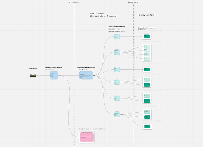
@Thomas_Mansencal started to reproduce @KevinJW diagram on a Miro Board.

Some of @daniele 's comments have already been added (the bottom diagram I think) :

  • I would not put output rendering in the scene referred bubble.
  • I would clearly separate LMT from the rest.
  • The output rendering is the collection of processes rather than one specific box.
  • You could put the “display encoding” ( EOTF and Matrix) on each leave, to clarify that the ODT should not have anything more in it.

You can make some notes on the board to share your thoughts. Cool !

And here comes stupid question#1. :wink: During meeting#3 there was a conversation about AP0 and AP1 spaces with the following comments :

Originally AP0 was meant to be the exchange and working space.

[The rendering transform] flips between AP0 and AP1 a few times.

When you look at the CTL code for the RRT and the ODT, there are indeed several transforms :

In the RRT :

  // --- ACES to RGB rendering space --- //
    aces = clamp_f3( aces, 0., HALF_POS_INF);  // avoids saturated negative colors from becoming positive in the matrix

    float rgbPre[3] = mult_f3_f44( aces, AP0_2_AP1_MAT);

    rgbPre = clamp_f3( rgbPre, 0., HALF_MAX);

In the ODT :

// OCES to RGB rendering space
float rgbPre[3] = mult_f3_f44( oces, AP0_2_AP1_MAT);

I am wondering if those transforms are still necessary with AP1 being the working space today. I can see in the diagrams that ACES2065-1 is considered the scene-referred space. I am curious about why…

Thanks for your answers,
Chris

The AP1 to AP0 at the end of the RRT and the AP0 to AP1 at the start of the ODT will indeed cancel each other out, so are strictly redundant. Implementations may in fact not include them for efficiency, as the OCES image data between the RRT and ODT is never exposed to the user.

I think their inclusion is more conceptual for the block diagram, as the intent is that image data is in AP0 as it passes from one block to the next. But what an implementation actually does is not important, as long as it achieves the aim.

Hello, thanks Nick for the reply and I also wanted to share some updates about “my little experiment” on the Miro board.

I think we were able yesterday to move forward with a more representative diagram from Daniele’s idea. Here is my thought process (based on the two last meetings’ notes) :

  • The fork should not be at the LMT.
  • There can only be one rendering intent.
  • Display transforms should be as pure as they can be (matrix + inverted eotf).

Based on all these assumptions, the only solution I could come up with was a three-stage process.

I am clearly not the most adequate person to do that but I have time on my hands and I find the exercise particularly stimulating. :wink: Interestingly enough, there was a conversation on Slack with some very interesting points that I think are worth sharing with the VWG.

First point was about similarities between Daniele’s idea and OCIO2 :

there’s a lot of conceptual overlap between some of the stuff Daniele demonstrated and some of the OCIO-2 architecture / design. (basically, from left to right, ColorSpaces —> Looks —> ViewTransforms —> DisplayColorSpaces)

And the conversation even got to a more interesting point :

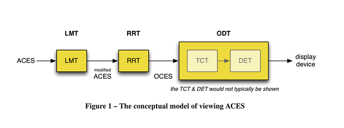
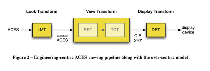
There’s a super obscure ACES technical bulletin […] — TB-2014-013 — that provides an alternate “block diagram” conceptualization. It divides the ODT into two blocks: the Target Conversion Transform (TCT) and the Display Encoding Transform (DET). The DET is the “on-the-wire” stuff (ocio DisplayColorSpaces); and the RRT + TCT make up what OCIO calls a ViewTransform (for the ACES family, in this case)

I think it is a good thing that OCIO2, ACES2 and even BaseLight go to the same direction. It makes sense to me. So I have tried to adopt this terminology on the Miro board, because it is really helping the conversation I think :

  • View Transform is made of Rendering Reference Transform (RRT) and Target Conversion Transform (TCT).
  • Display Encoding Transform (DET) is the last step of the chain.

Finally, some wise words from Daniele :

I think this abstract discussion about system overall design is important before we jump into the details of one particular implementation. Keeping it abstract at this point is key. The less you specify explicitly and the longer you stay on the mechanic side the more general your system might be. For example my proposal would also still be true if we decide at a later stage to roll in spatial or temporal processing per viewing condition.

Thanks Zach, Sean, Nick, Carol and Daniele !

Regards,
Chris

1 Like

In your version of the diagram, what is the single RRT block doing?
I think our two diagrams are almost identical but you put in a single RRT, how is this different from an LMT, if it is just a single transform?
Is it really needed then?

1 Like

Well, that’s a proper question. And this is where I’m probably confused. :wink:

Yesterday, three main steps were listed (with the OCIO comparison) :

  • Look
  • View
  • Display

I think that’s a good summary of what we’re trying to achieve. So in my head :

  • LMT is the grading/creative choice
  • RRT is the gamut/tone mapping (which is not creative for the sake of argument, it is “neutral”)
  • TCT is the viewing conditions and overall display capabilities
  • DET is just the technical encoding step

Which makes me realize I have four steps… :wink: Maybe what you’re suggesting is to merge RRT + TCT into one block and have several of them ? But then we go back to the LMT being the fork… which is not what we want, right ?

Since the idea (that I love) is to give flexibility/modularity, I understood that having the RTT as the fork would make things easier. Because you may want to keep you creative grade (LMT) while swapping the whole DRT.

Something I want to ask you about your diagram is : how the multiple output transforms from the ACES family are connected ?

Too many riddles :wink:
Chris

I see where you are coming from.
Your initial diagram focused on displays rather than on transforms.
I made yet another version of yours a bit to the right. I removed some details to not loose ourselves in the details just yet.

Thanks, that’s much appreciated. Food for thought !

Chris

The LMT is scene linear to scene linear, and the RRT is scene linear to display linear if I’m not mistaken.

Having just read through Ed’s paper (that Alex posted), I can see the value of a single RRT, and I would also keep Chris’ four steps segregated and not combine the RRT & TCT:

The RRT would provide an initial tonescale and gamut mapping and, as the name implies, is the “reference” for all other display transforms (it’s the “golden image”, despite not being actually visible; it’s purely theoretical as no current or even near-future display technology could accurately show it). This is the scene linear to display linear transform, and there is only one in this case. It needs to have established specifications for the theoretical display it is transforming to; we could propose, for example, something like 10,000nit peak, D65 white, AP1 (or maybe BT.2020) primaries, dark surround.

Transforms for “real world” displays (BT.709, Rec.2100 PQ 1k, DCIP3, etc) are based off this theoretical display, so the TCT for each of these displays is distinct, and mapping “down” (smaller gamut and/or dynamic range) from the theoretical display (display linear → display linear).

Both the RRT and TCT are potentially modular. You can exchange the single RRT for a different renderer (K1S1-esque, etc) and it would affect all outputs equally. Or you could swap out an individual TCT if desired. This would accommodate (I think it was Thomas that was proposing) a display-level LMT; except instead of an in-line LMT for a particular display, it would simply be a different TCT with the desired alterations.

Unless I’m thinking about this differently than Chris, to clarify the Miro board in Chris’ drawing the display linear line should be between the RRT and the TCT, as after the RRT you are in display linear space.