I managed to get a new simpler version of the chroma compression working. It’s available in my repo for testing as a prototype version CAM DRT v032-pex.
New in CAM DRT v032-pex prototype
- New chroma compression algorithm, old one is removed
- Cusp smoothing is now enabled by default
- Small change to custom LMS primaries
- Small changes to LMS compress mode to avoid NaNs/Infs
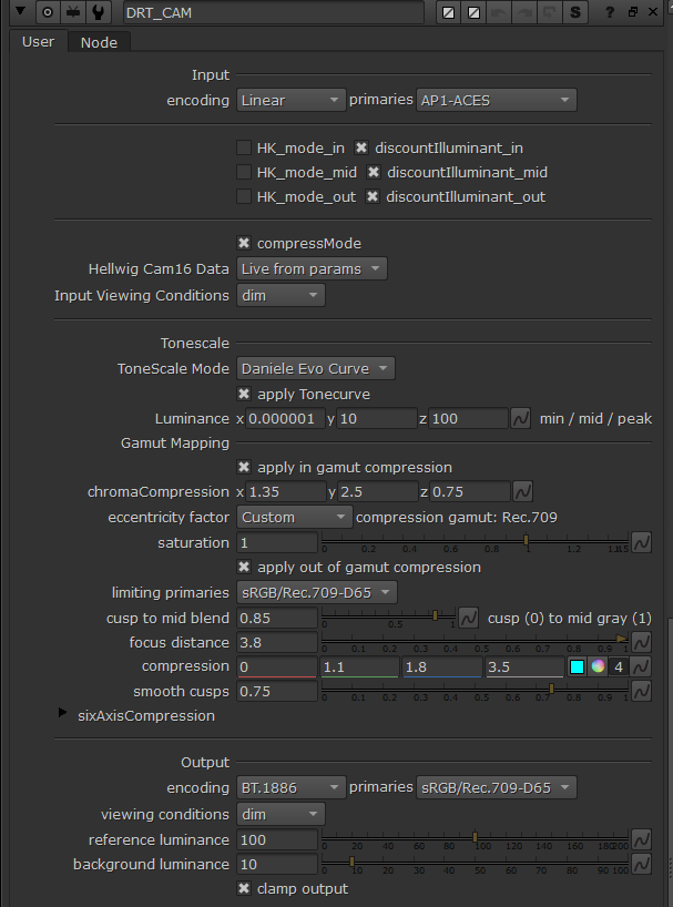
- Gamut mapper parameters changed
- ZCAM is removed
- Linear extension is removed
The New Chroma Compression (in-gamut compression)
The new algorithm is simpler than the old one and has only one curve as opposed to three curves the previous algorithm had. The steps of the new algorithm are as follows:
- Scale down M (colorfulness) by tonescaledJ / origJ
- Normalize M to compression gamut cusp (becomes hue-dependent)
- Compress M with a compression curve. Compression is increased as tonescaledJ increases to create the path-to-white.
- Denormalize M with the gamut cusp
- Apply global saturation to taste, boosting saturation in shadows more
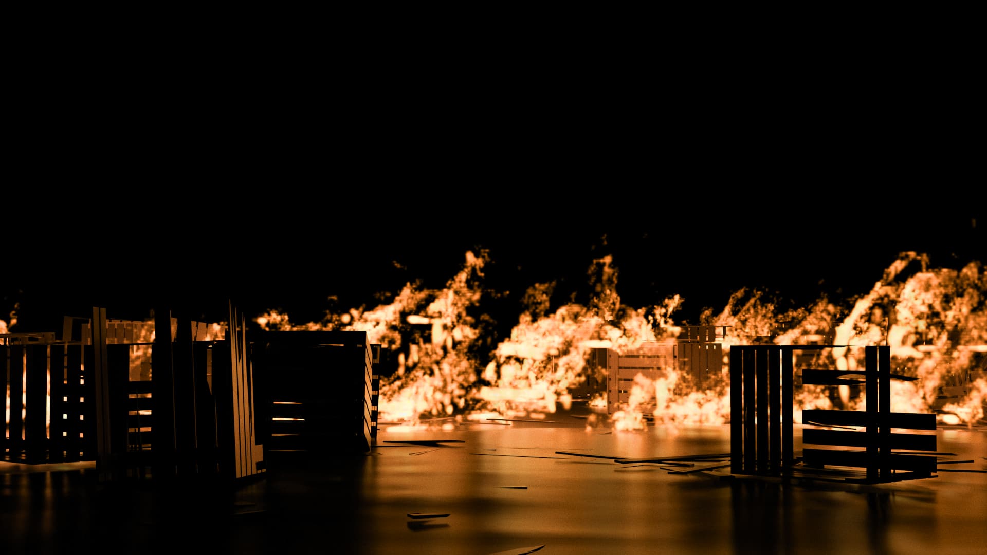
The M is normalized to the cusp of a compression gamut. The compression algorithm then compresses the colorfulnes in 0-limit range. It does not compress anything beyond the limit. This makes this curve more controllable than the previous one and it protects pure colors well. Forward direction has better yellows than previously which helps with rendering of fire/pyro, etc. Path-to-white is IMO better than in the previous algorithm. Path-to-black is on par with the previous one with slightly more colorful noise.
The Compression Gamut
The default chroma compression gamut is always Rec.709 but I think it could also be something else, including a custom gamut specifically chosen for the compression use case. This gamut doesn’t change even when limiting/encoding primaries are changed. This means it keeps the range that it compresses (0-to-limit) always the same regardless of the display gamut. This may or may not be a good idea…
The gamut cusp is always scaled with an eccentricity factor (ET). The current implementation has 3 ETs to choose from: CAM16, Hellwig2022 and Custom. The default is Custom and provides the best forward and inverse directions of the three. Without applying the eccentricity factor it seems the shape of the resulting compression fits the display gamut poorly.
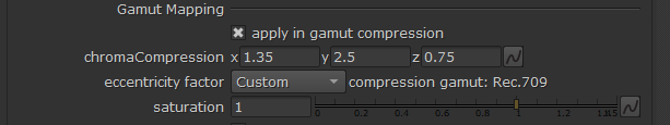
The 3 compression parameters are limit, compression strength, and compression expansion rate.
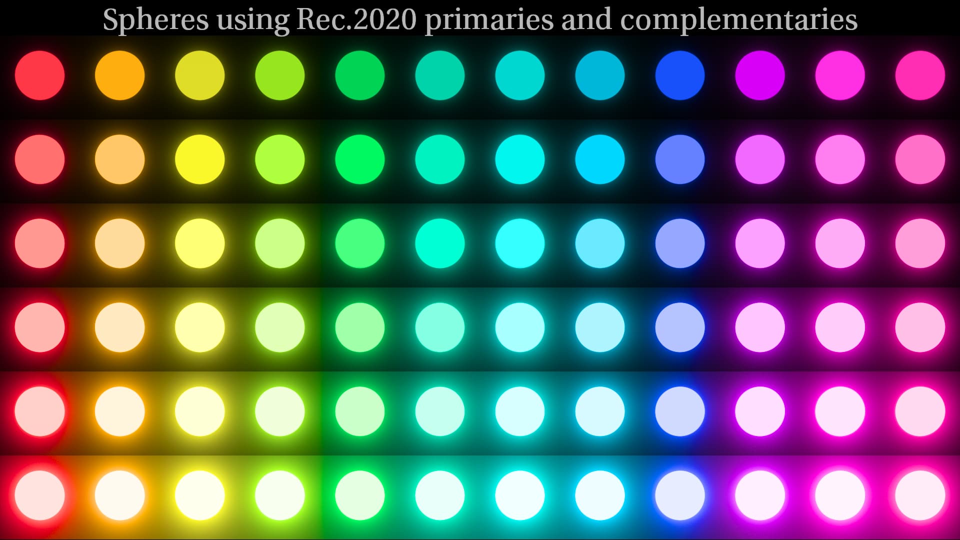
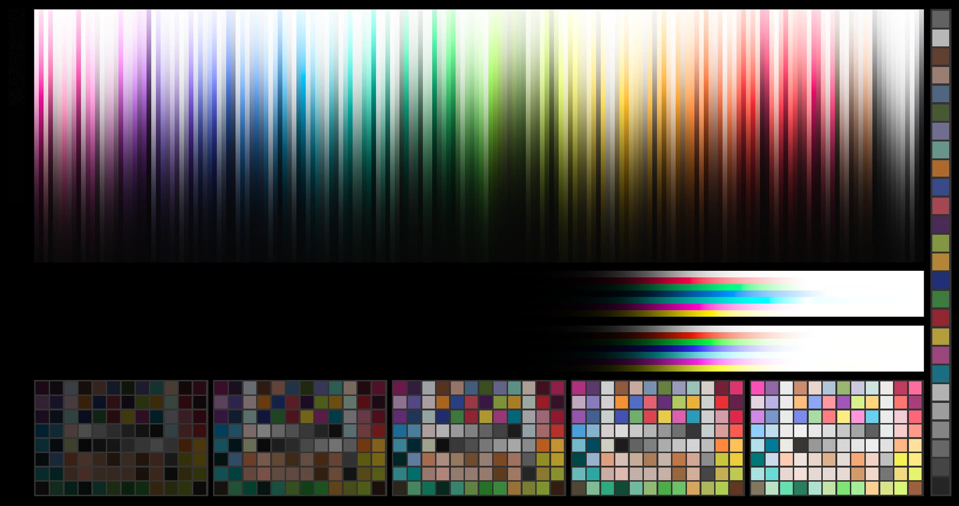
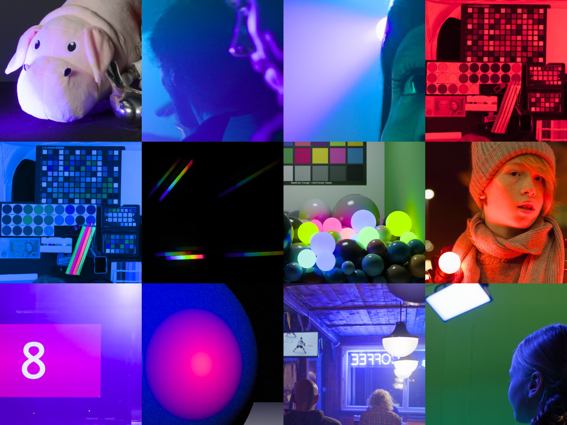
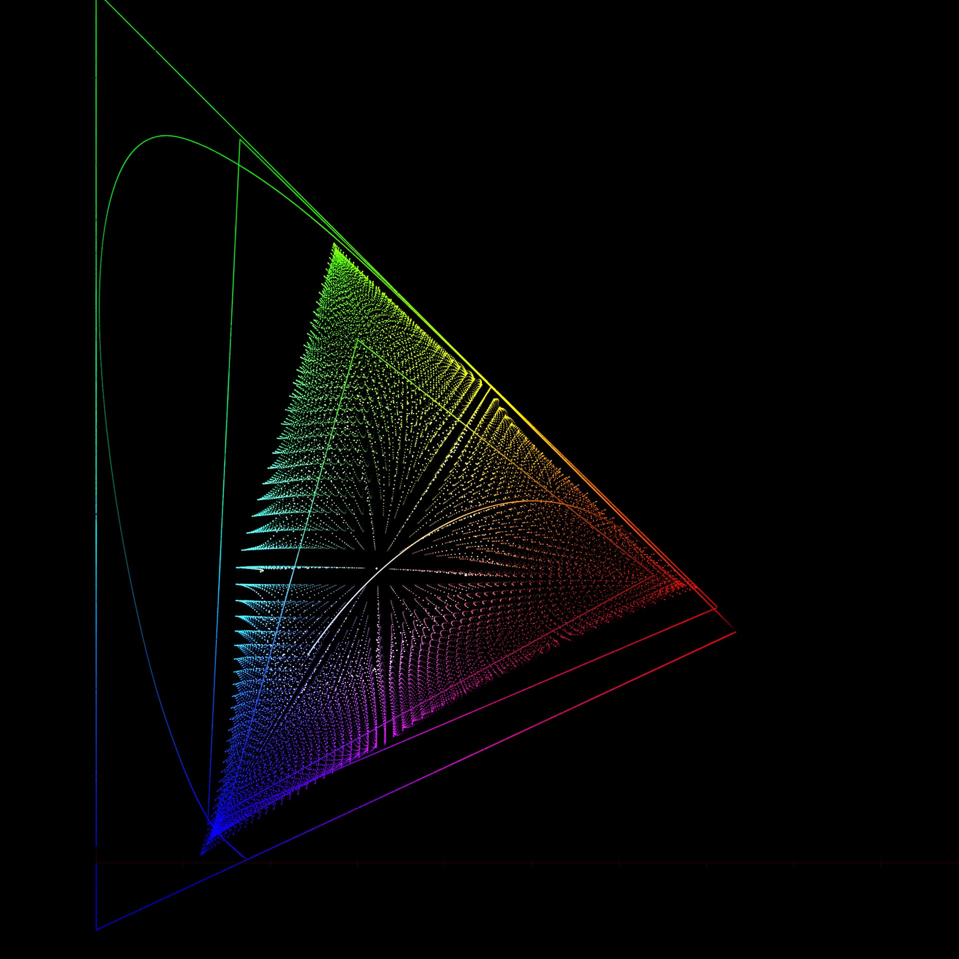
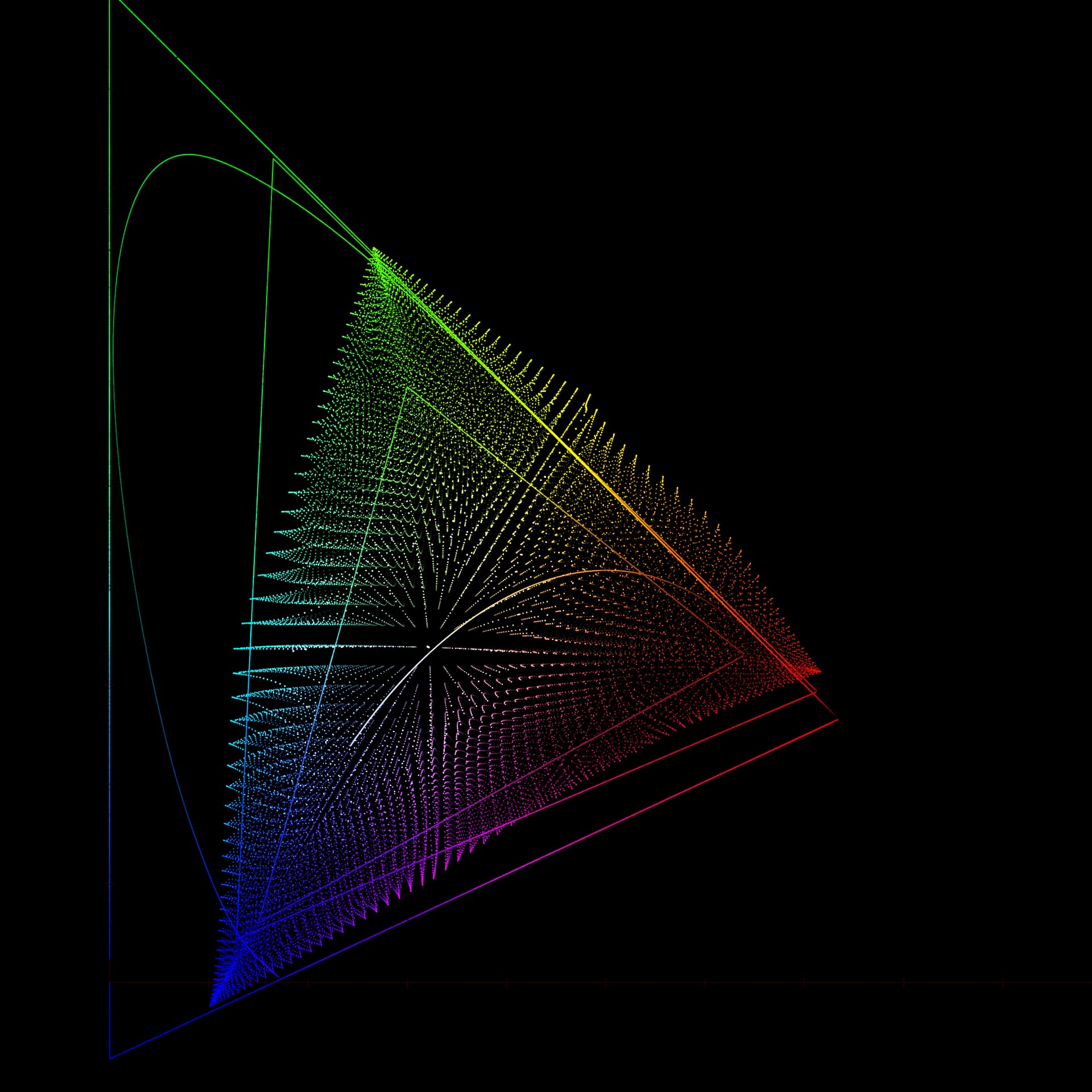
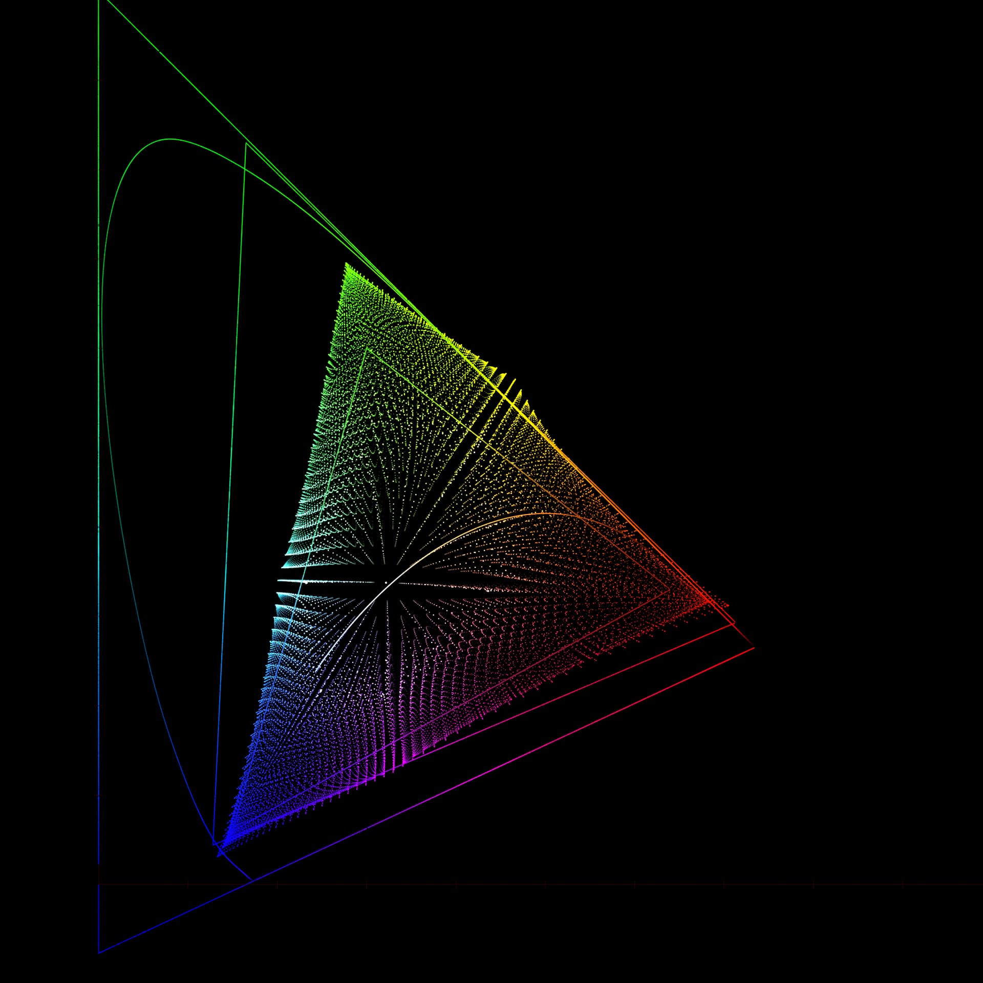
The Rec.709 Inverse
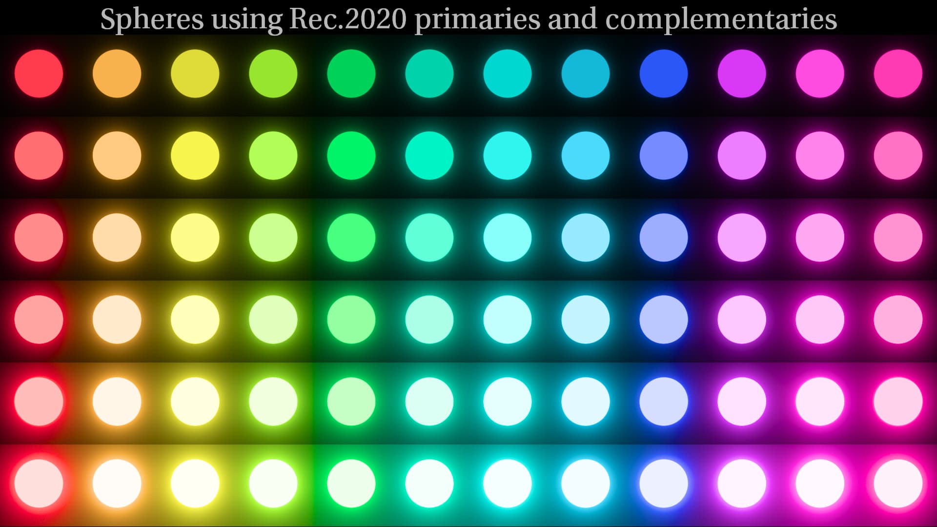
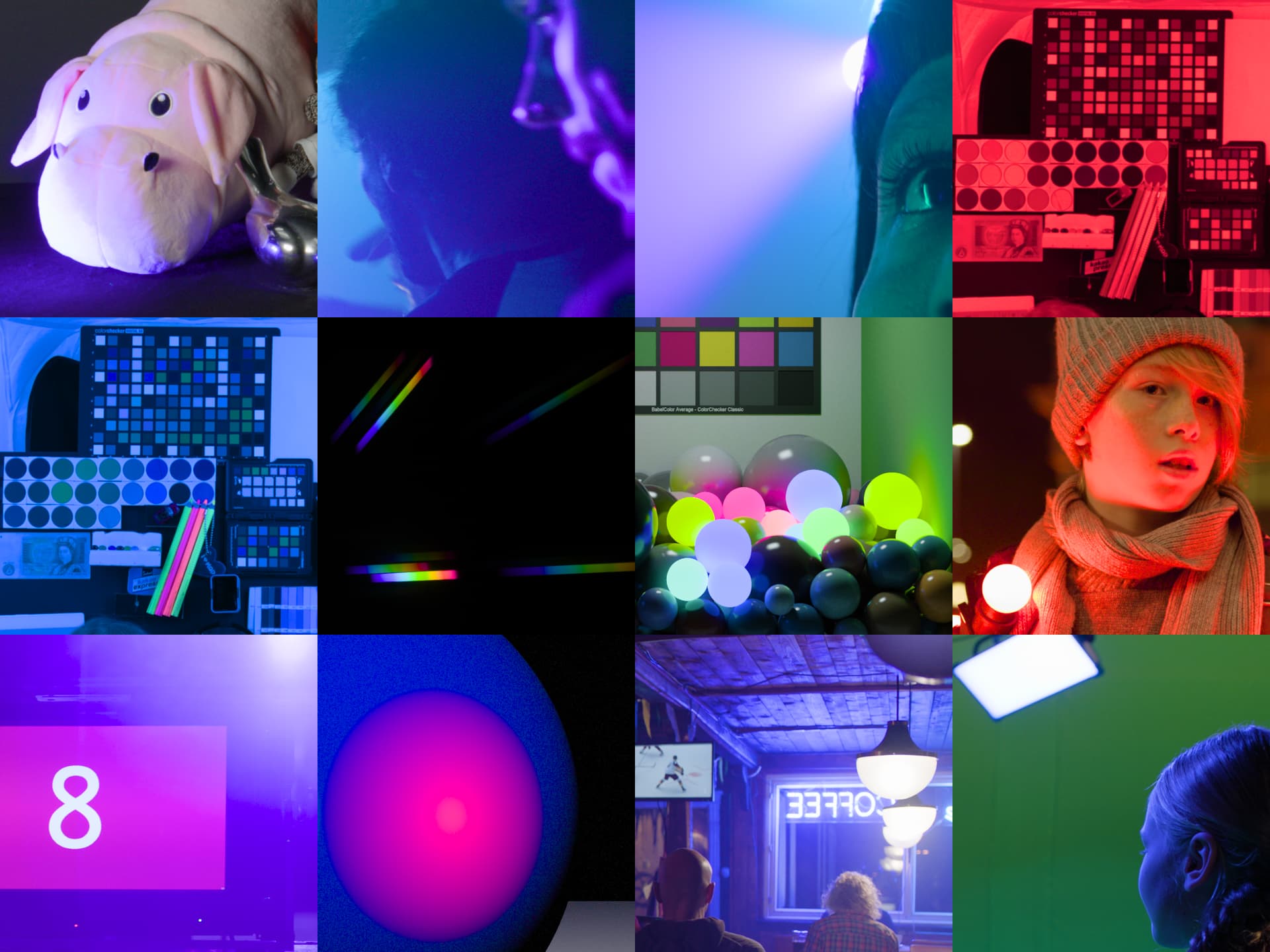
Following images show the inverse compared to CAM DRT v031 (second image):
Following images show the inverse with CAM16 and Hellwig2022 eccentricity factors applied:
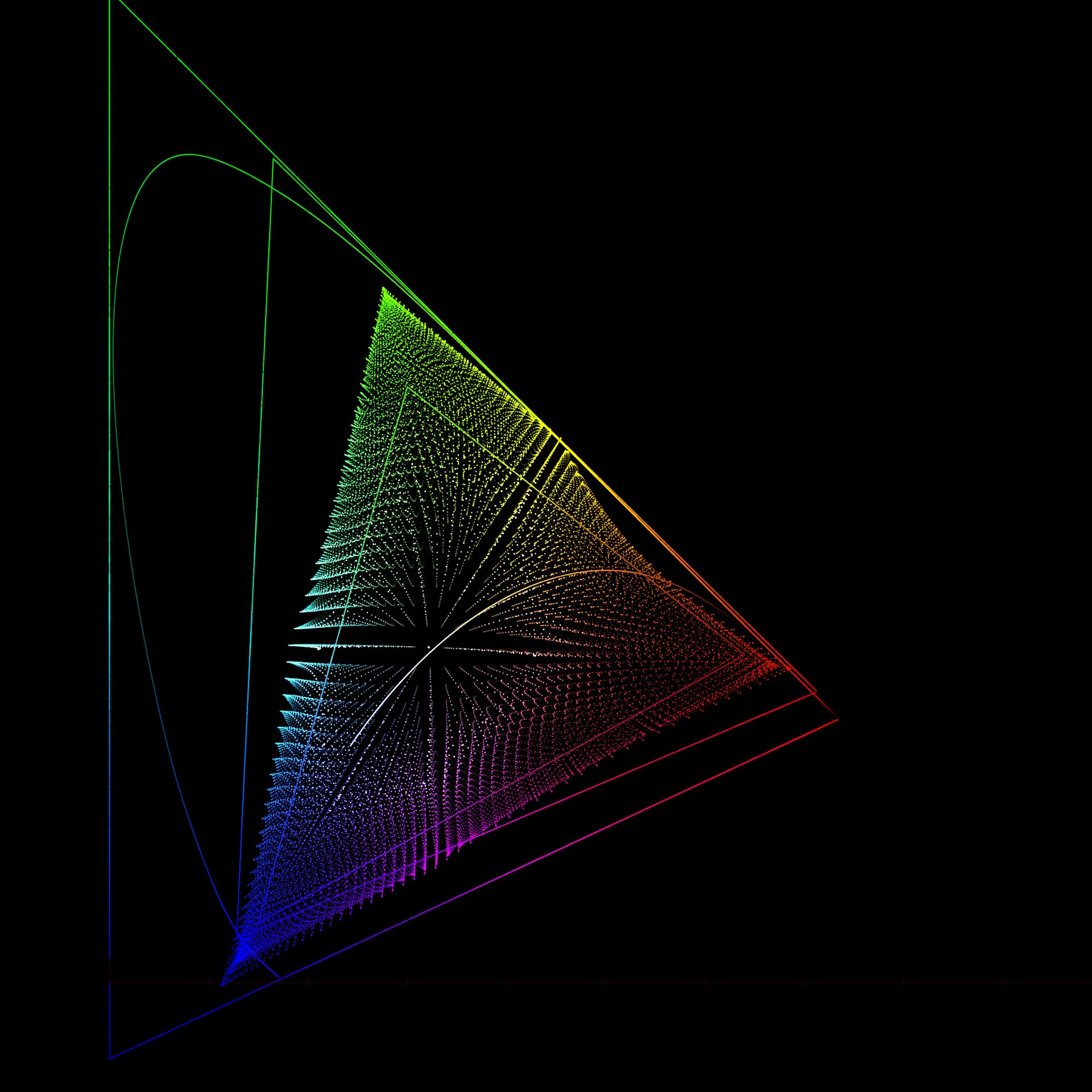
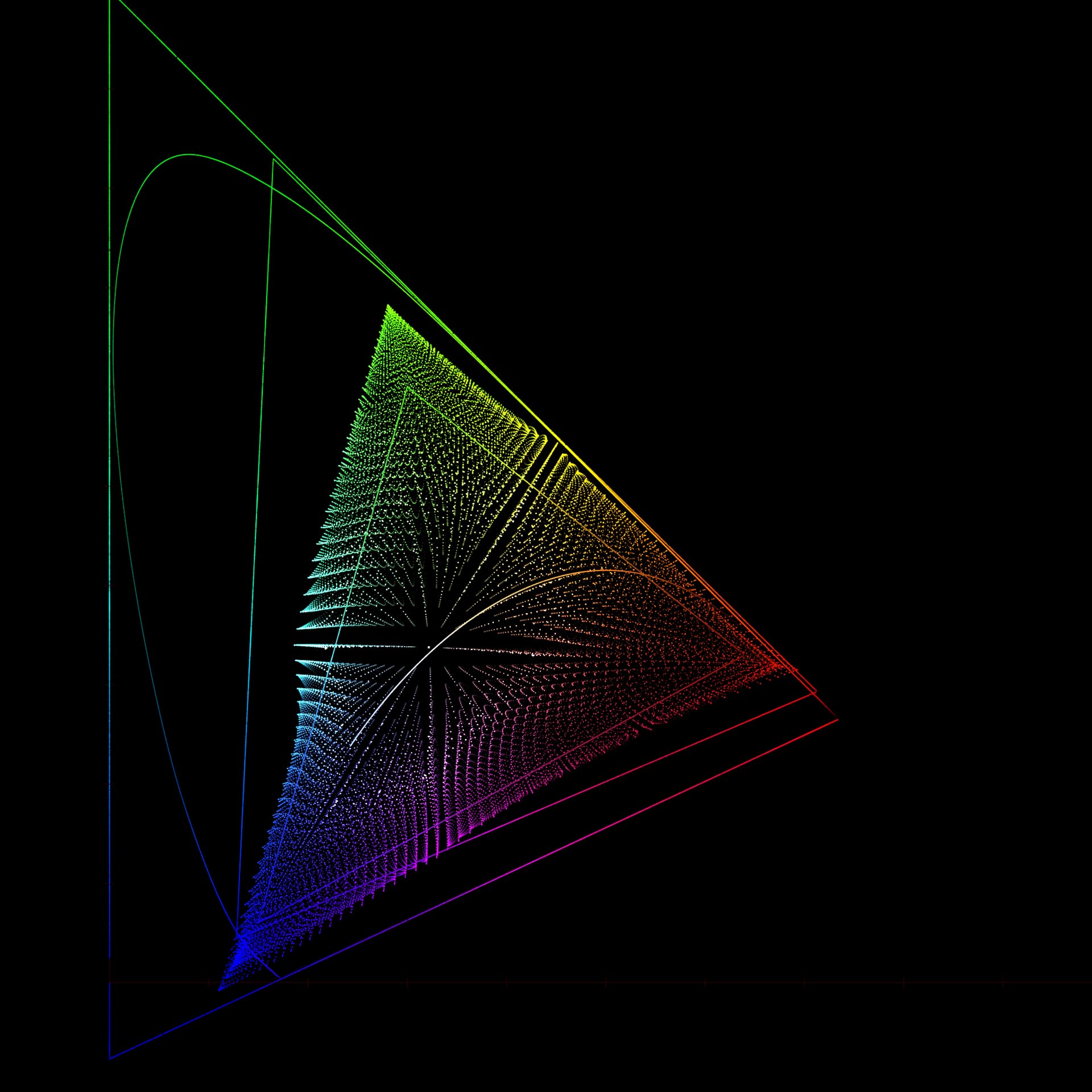
Following image show what the inverse looks like when eccentricity factor is not applied in compression (all else being equal):
SDR/HDR Rendering
The match between SDR and HDR is decent but not perfect. Shadows can be more colorful in HDR compared to SDR. Needs more testing and adjustment. Path-to-white for normal range of colors appears to be almost identical in SDR and HDR, which is an improvement over the previous chroma compression, IMO.
Purer colors can now appear even more pure in HDR than before because chroma compression no longer compresses as far out as it did before. Pure red in particular seems to come out really hot on HDR RGB screen (with either P3 or Rec.2020 limited primaries).
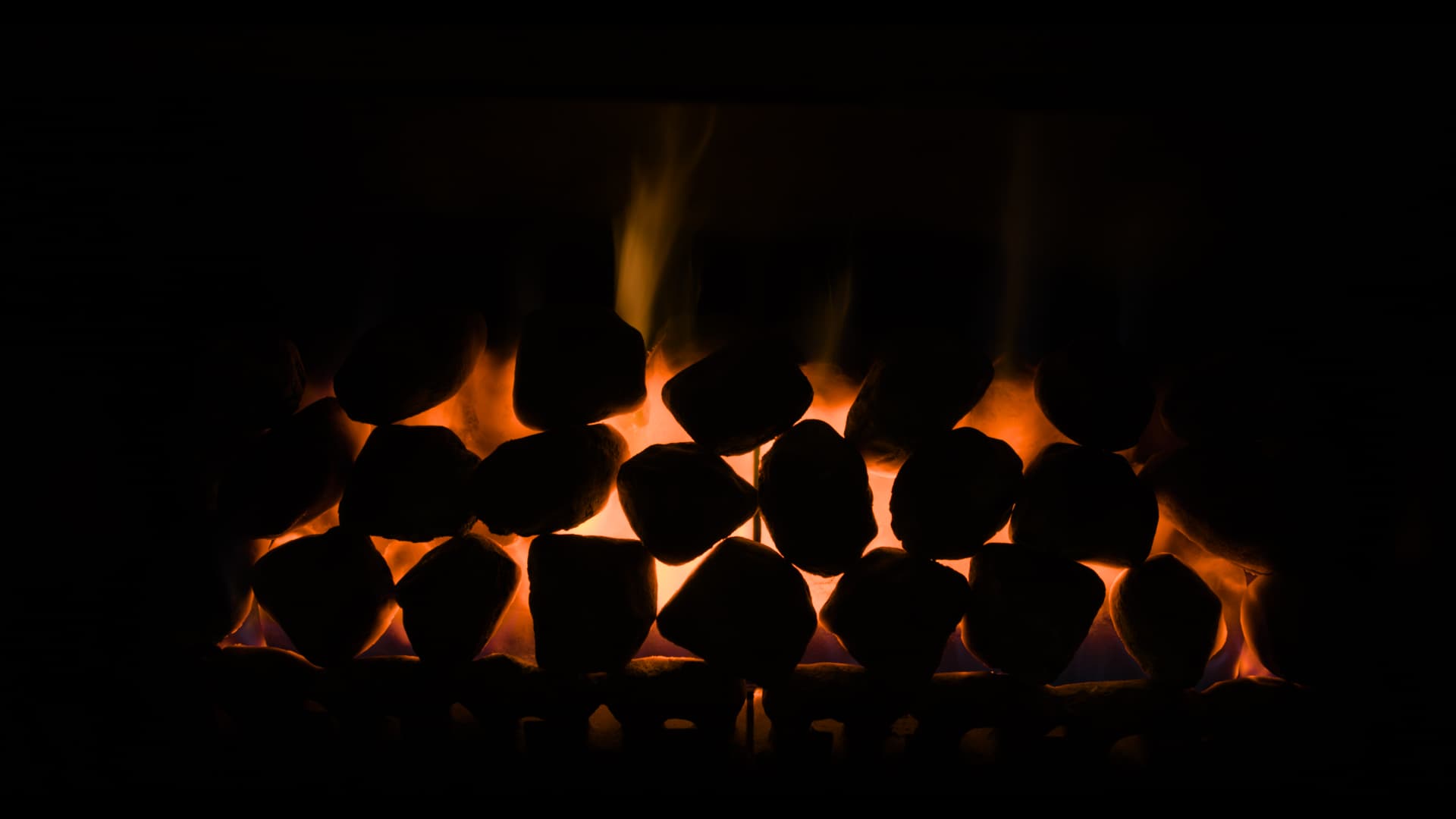
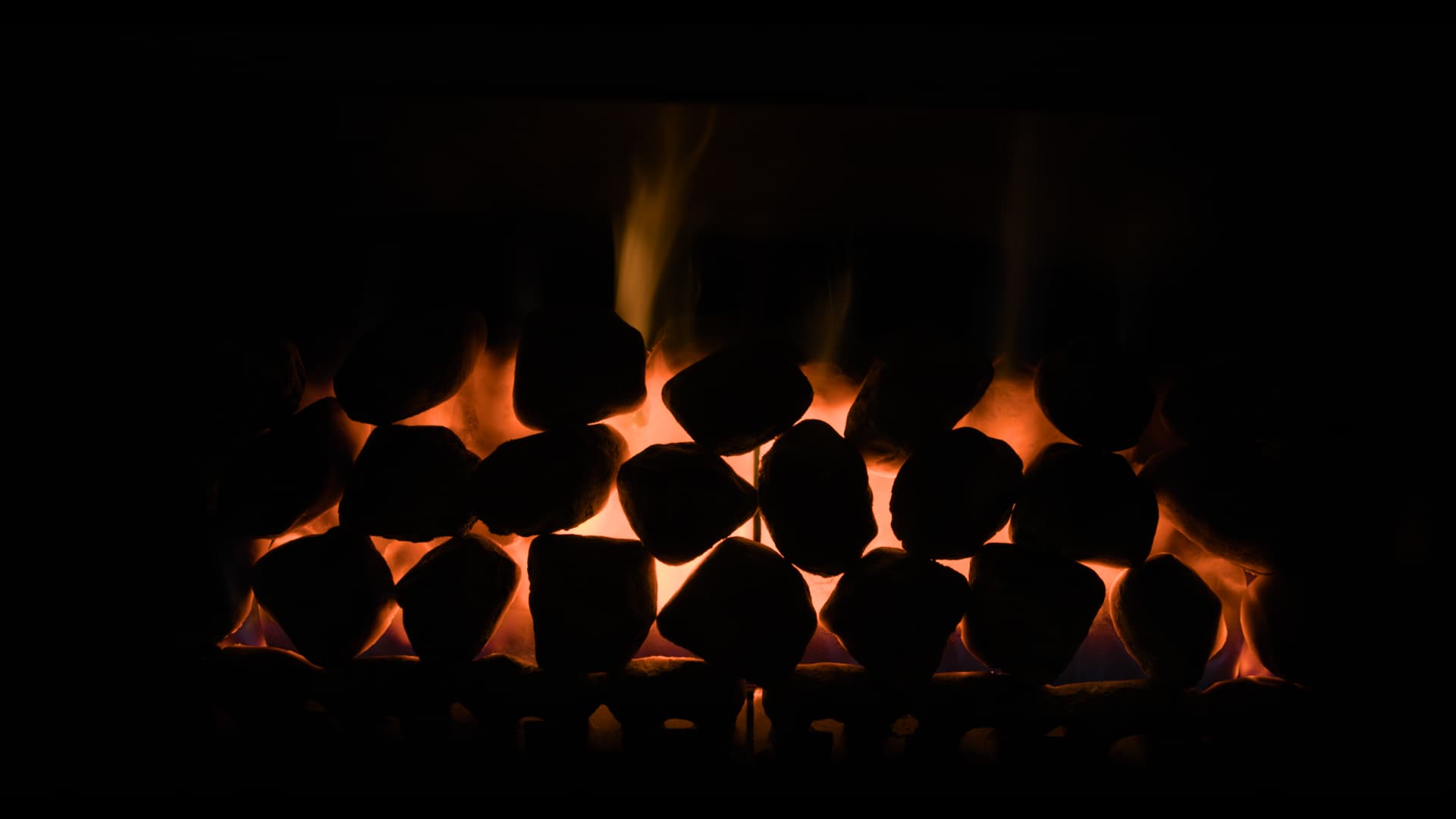
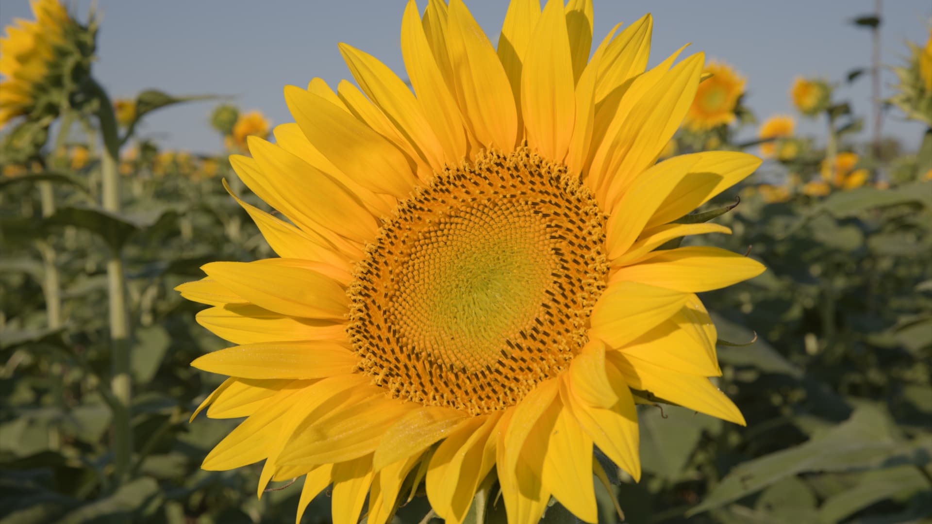
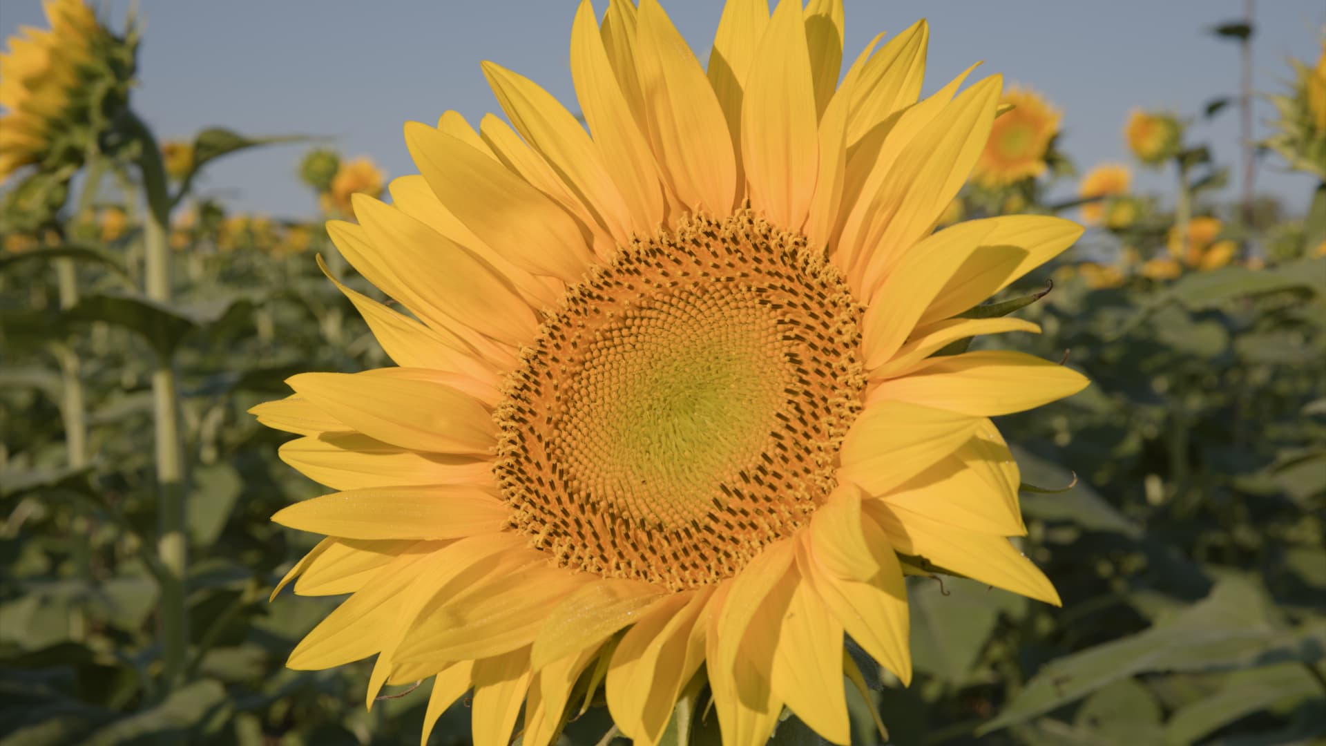
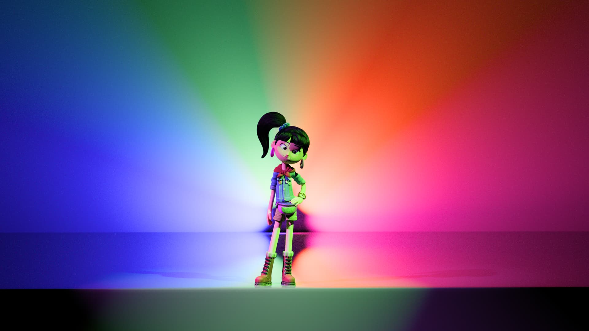
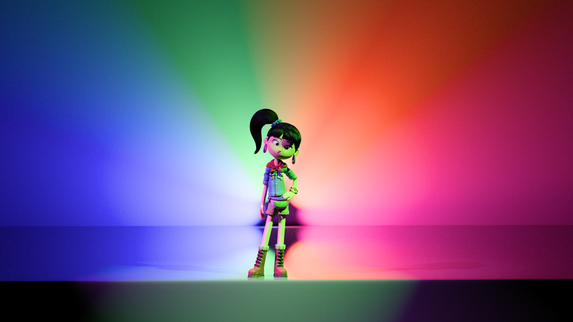
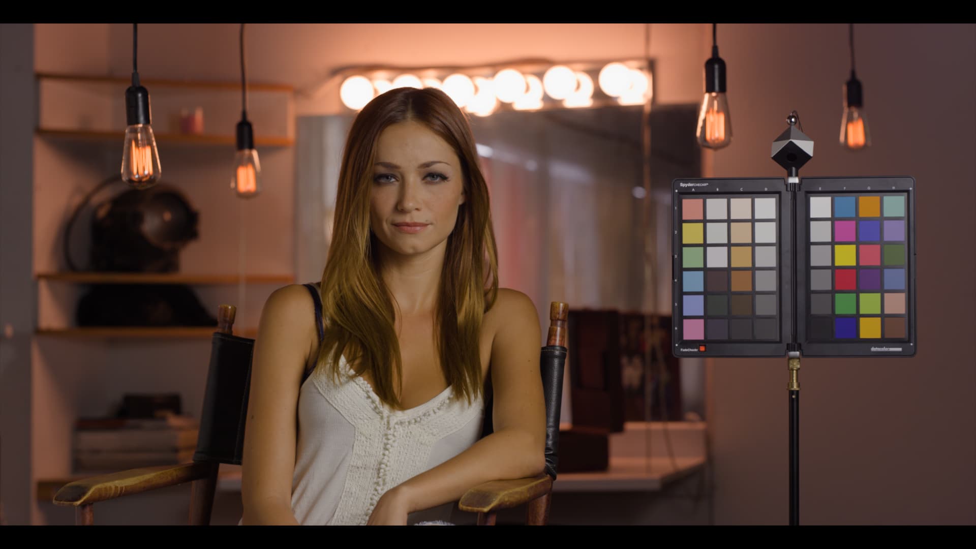
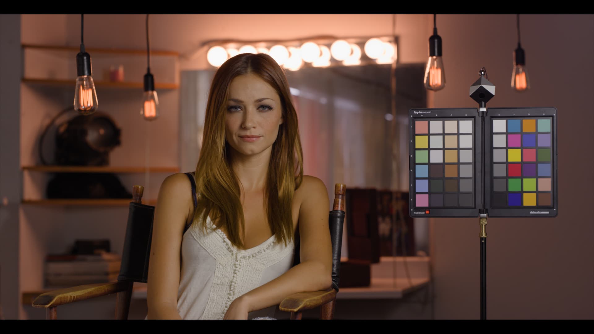
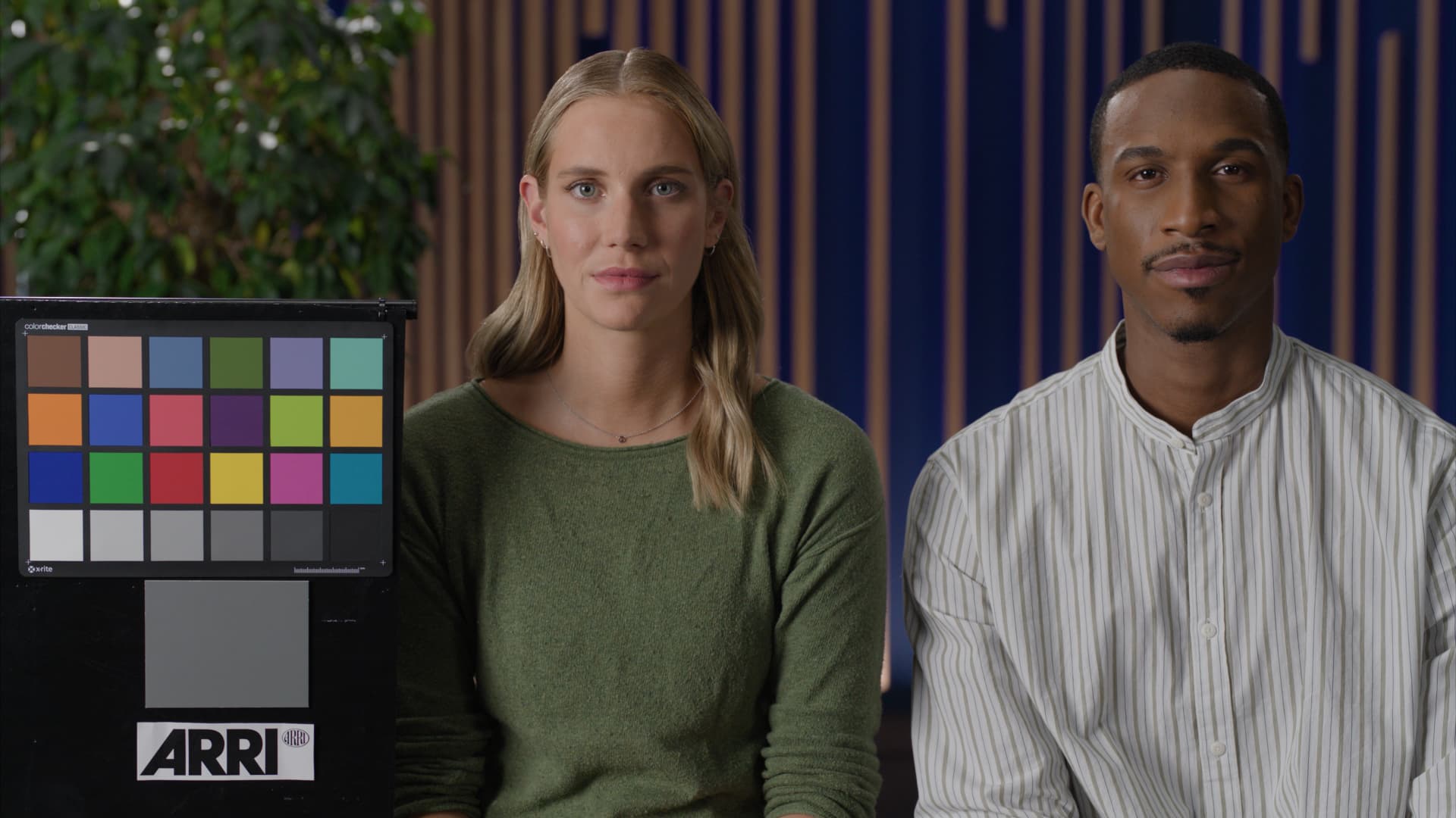
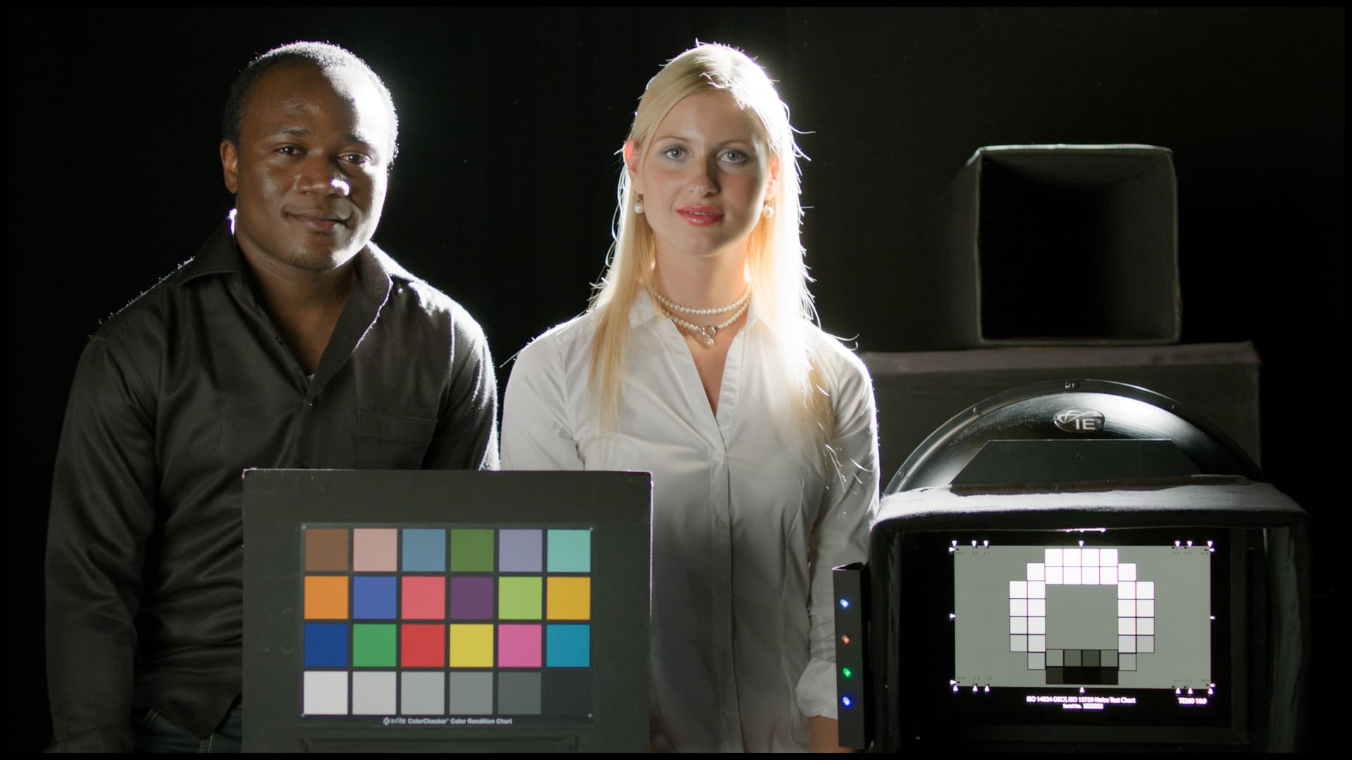
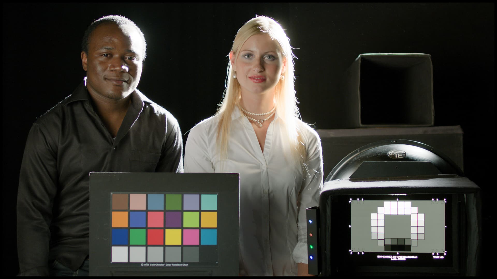
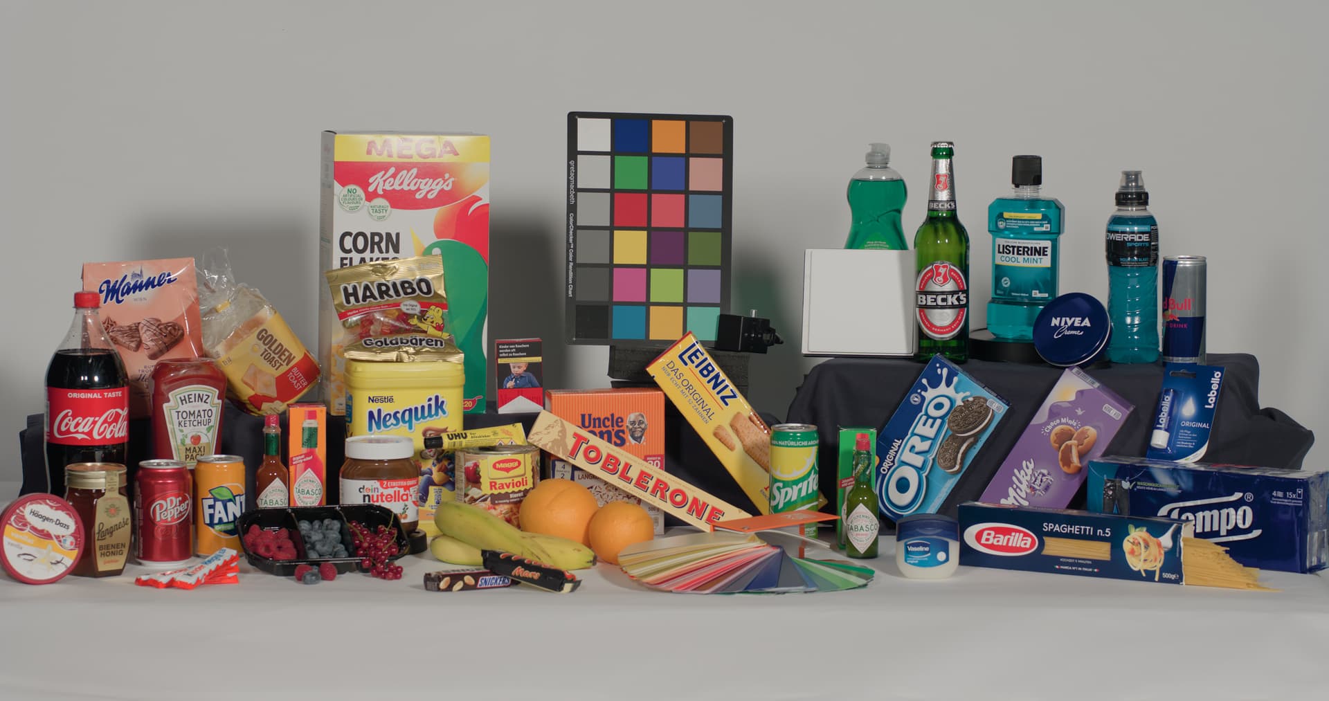
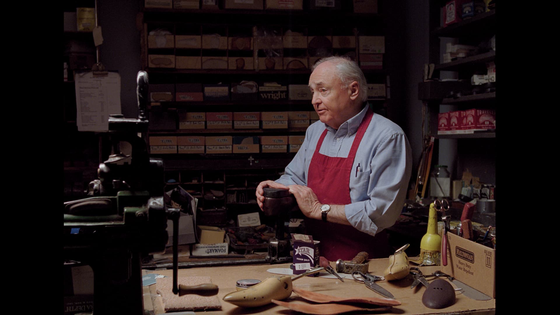
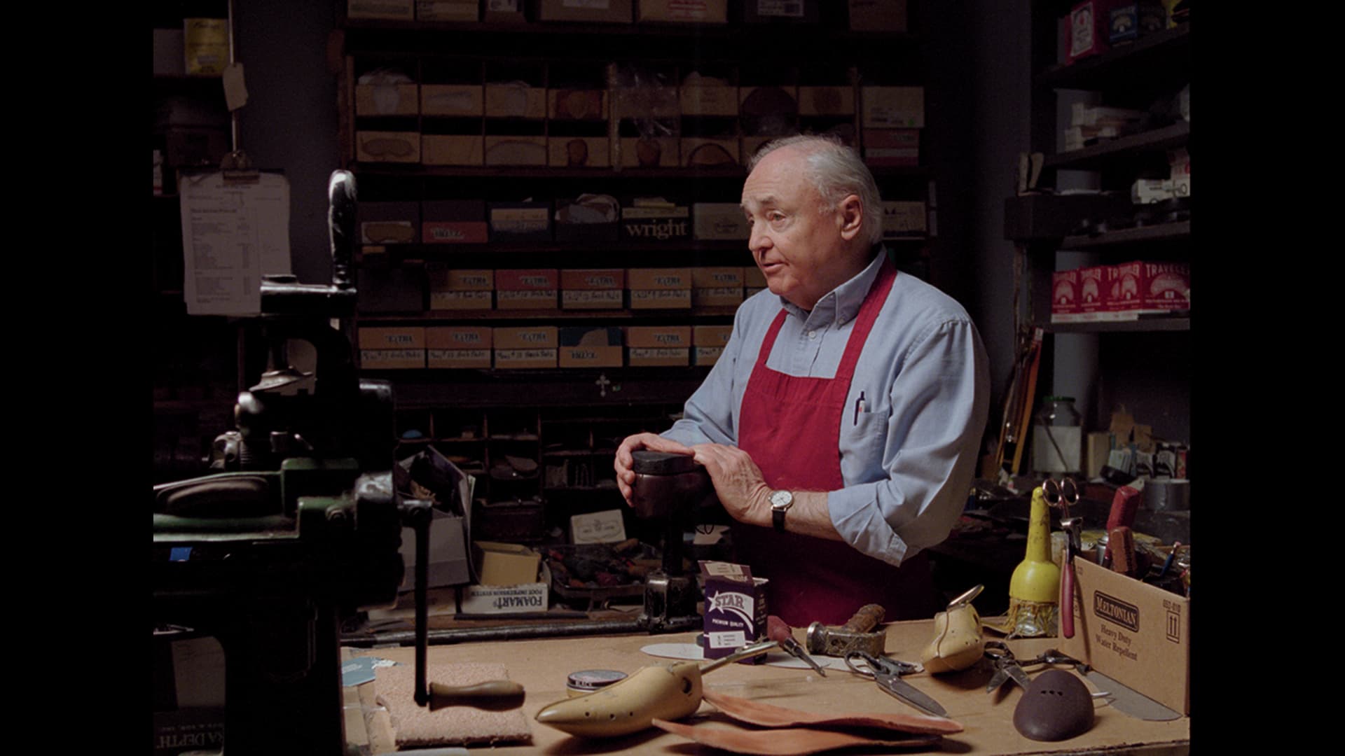
Example Images
First image is CAM DRT v032-pex, second image is CAM DRT v031 for comparison: