Discussion around the current state of what was know as Candidate C/ZCAM DRT has become a bit spread out (And the original ZCAM thread seems to be only visible by search for me), so I thought it might be a good idea to make a new home for discussion specifically around what I’m not referring to as CAM DRT.
I’m calling it CAM DRT for now as it now contains both the ZCAM and Hellwig 2022 models as alternative code paths.
My current working version is v20.
Thanks to @priikone it’s no longer completely blowing up the GPU (and machine) with some images (infinite loop in the findBoundry function with some input values)
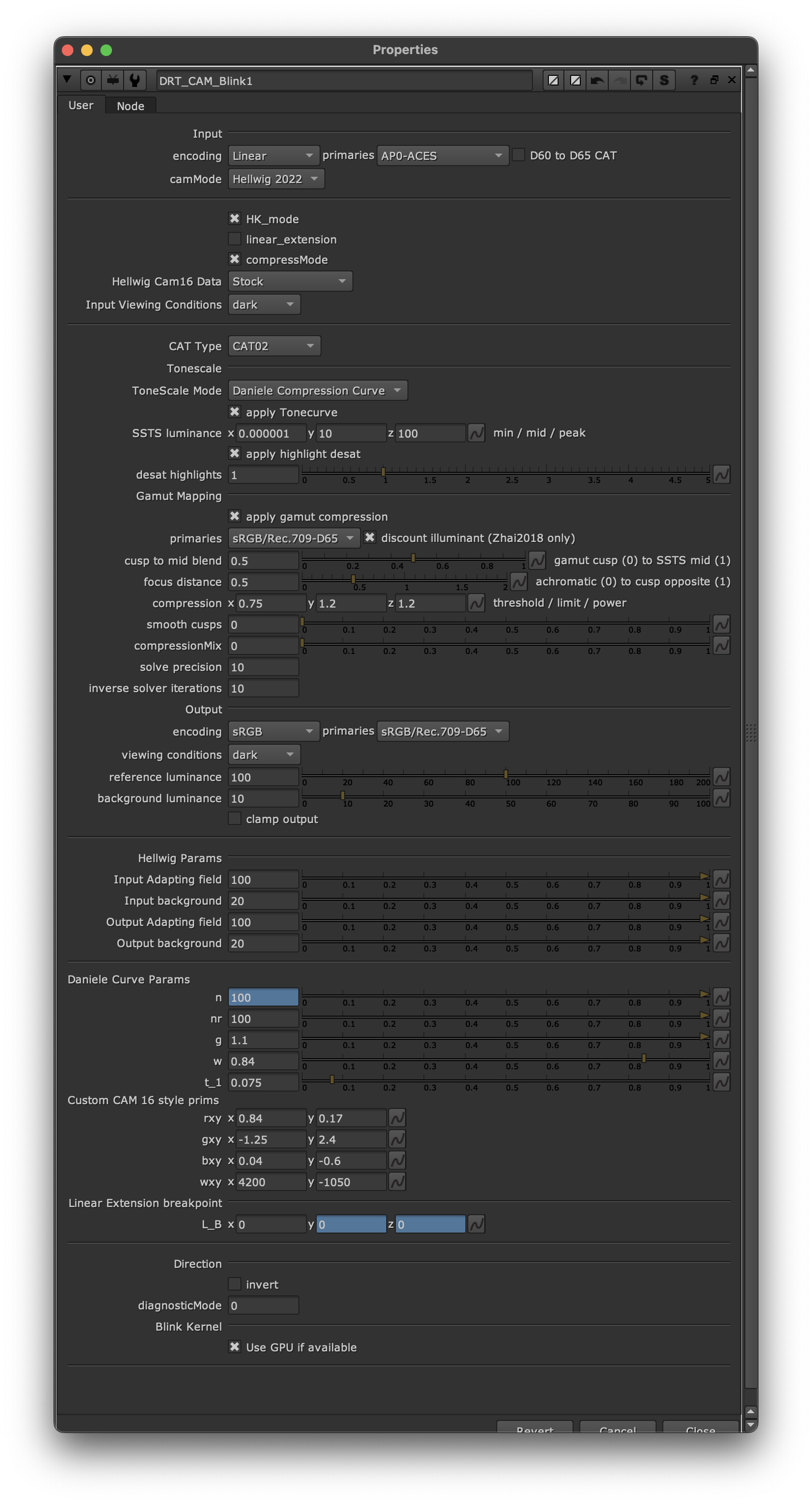
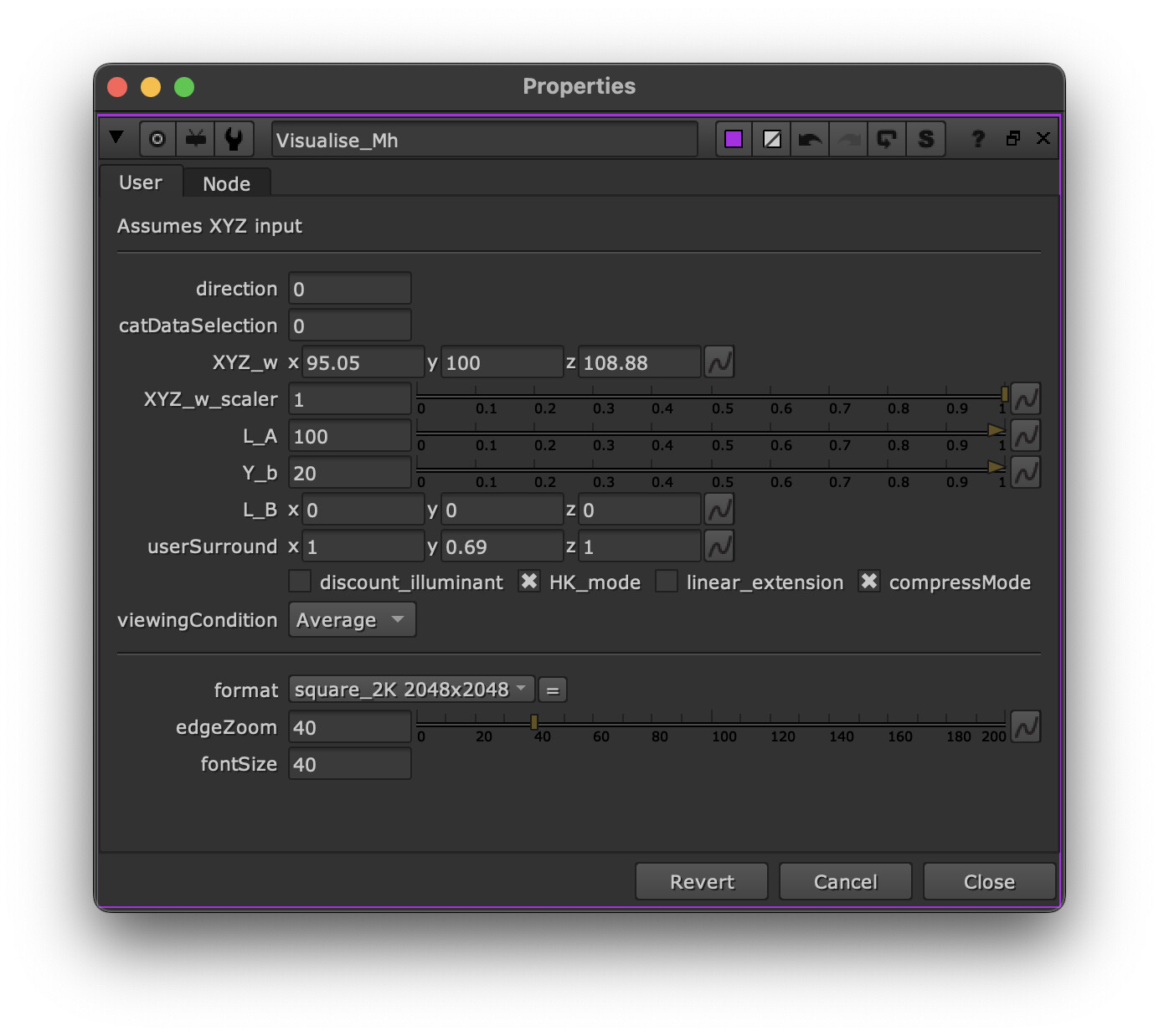
I’ve exposed a bunch of extra controls around input/output viewing conditons, and apapting field. None of these are well tested, and could cause unforseen issues, but please play with them. My sense is that the result of changing viewing conditions is super heavy handed, but adapting field is more reasonable.
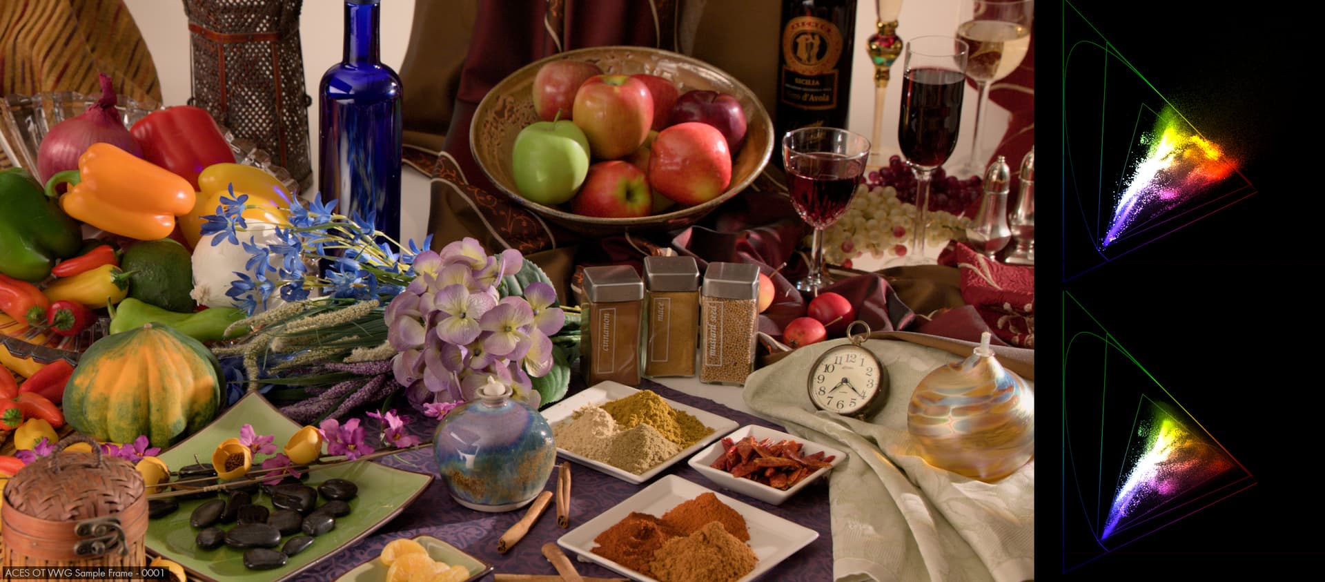
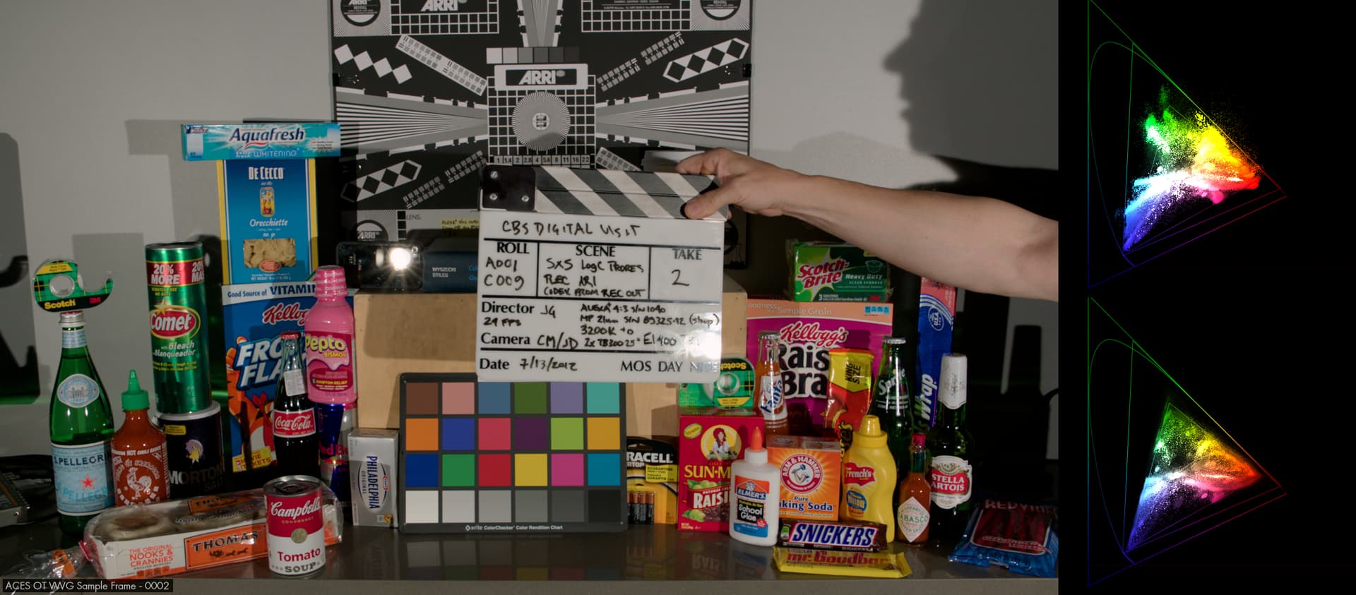
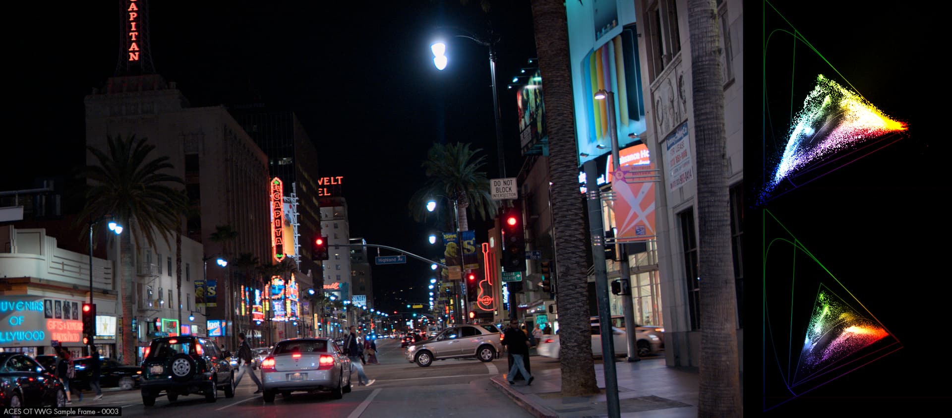
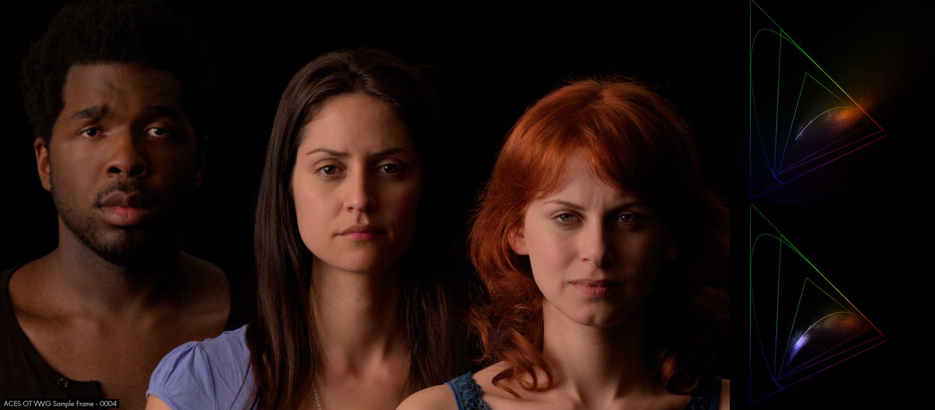
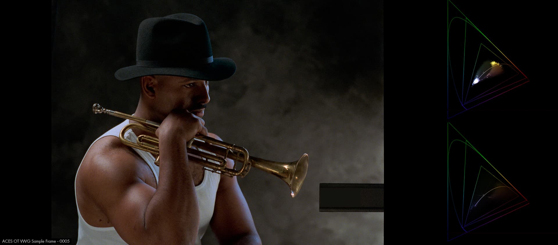
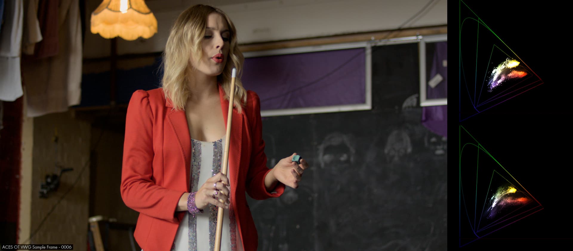
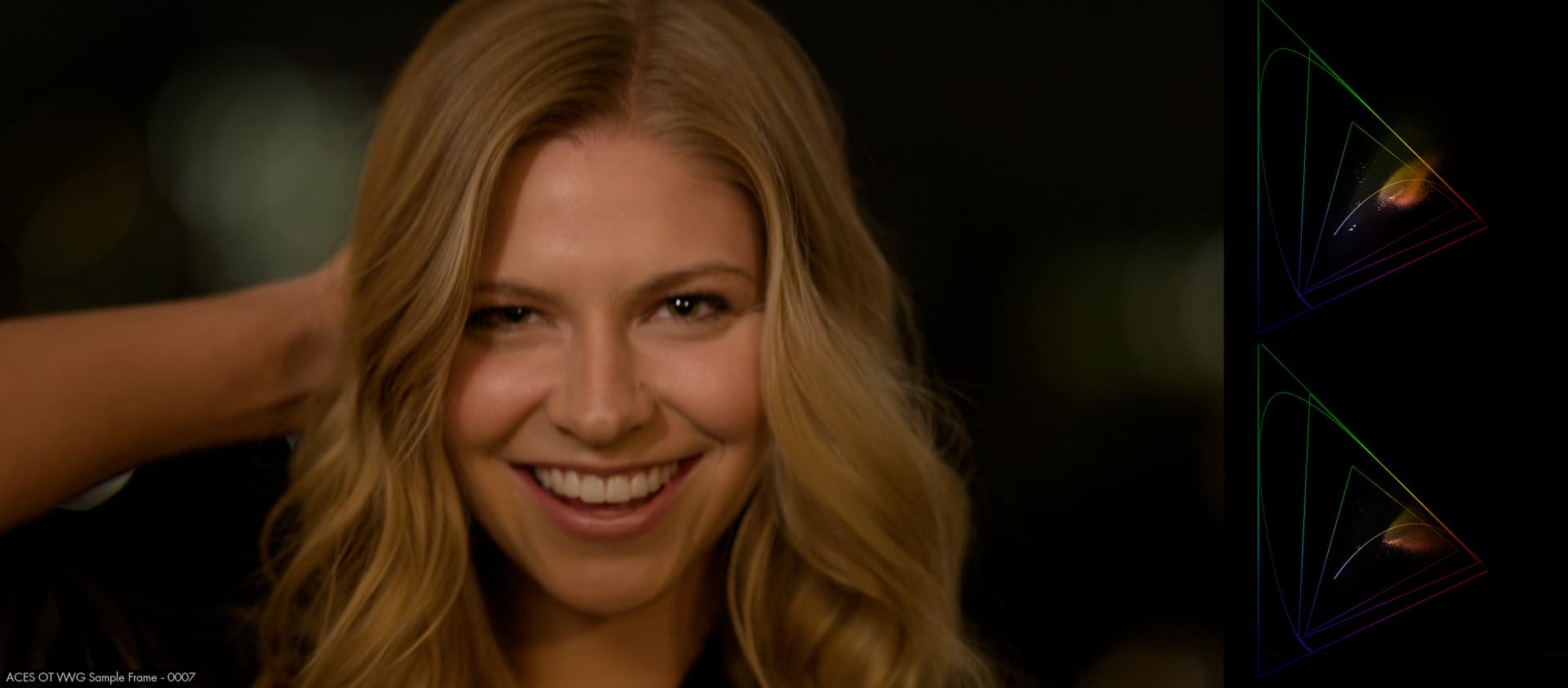
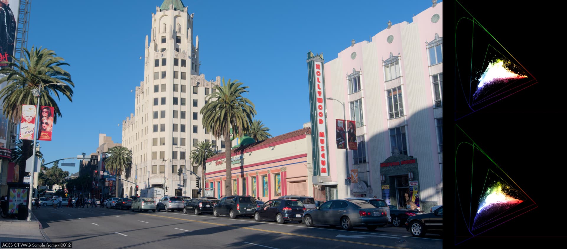
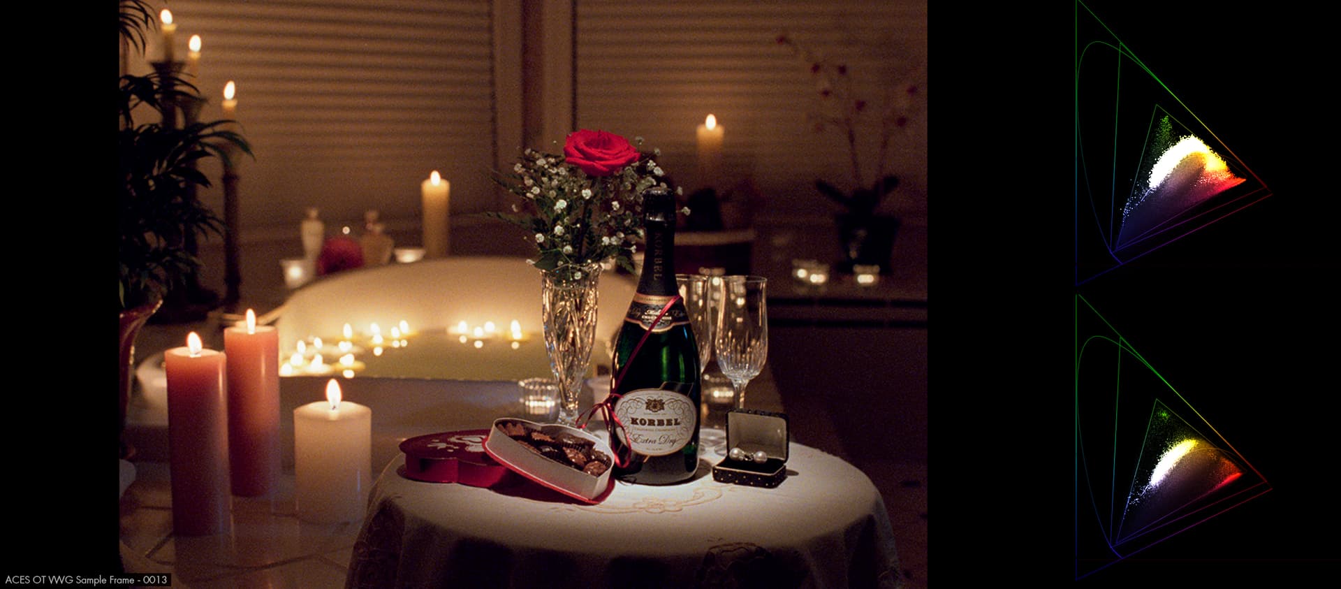
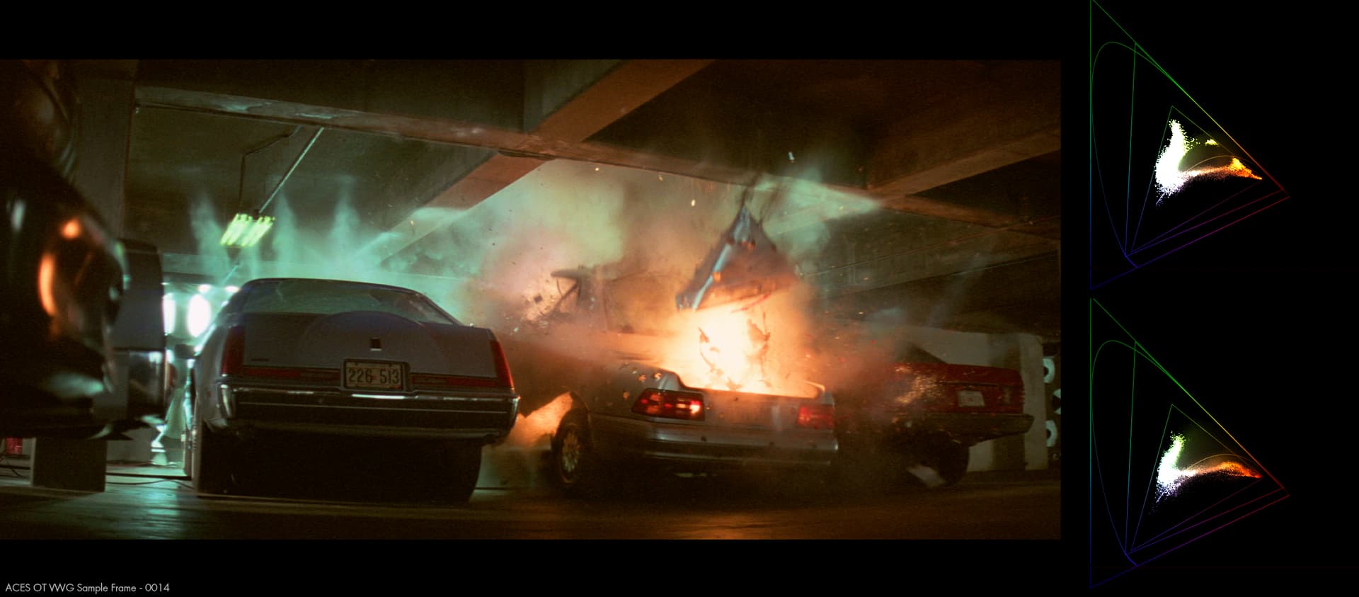
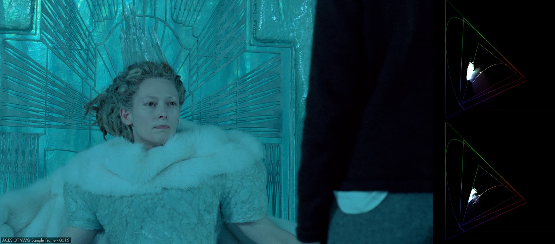
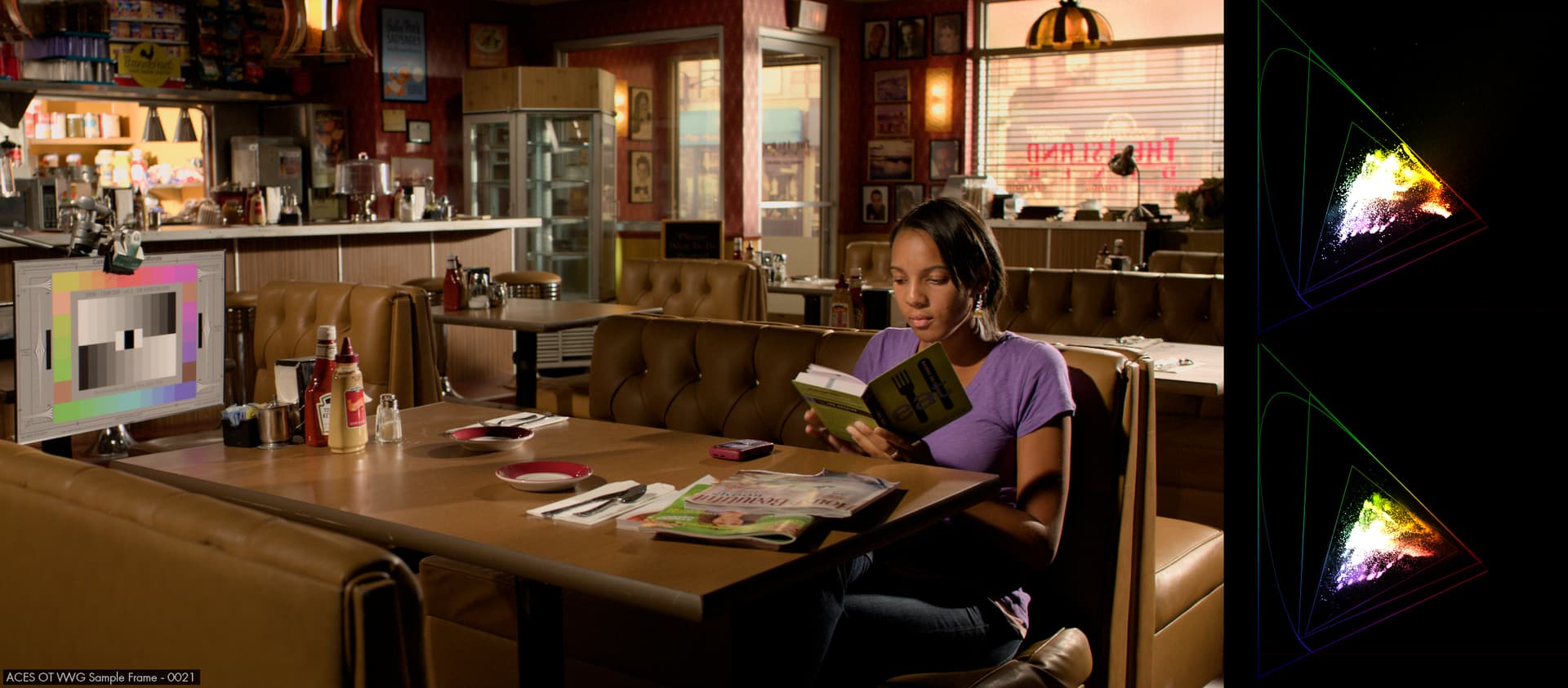
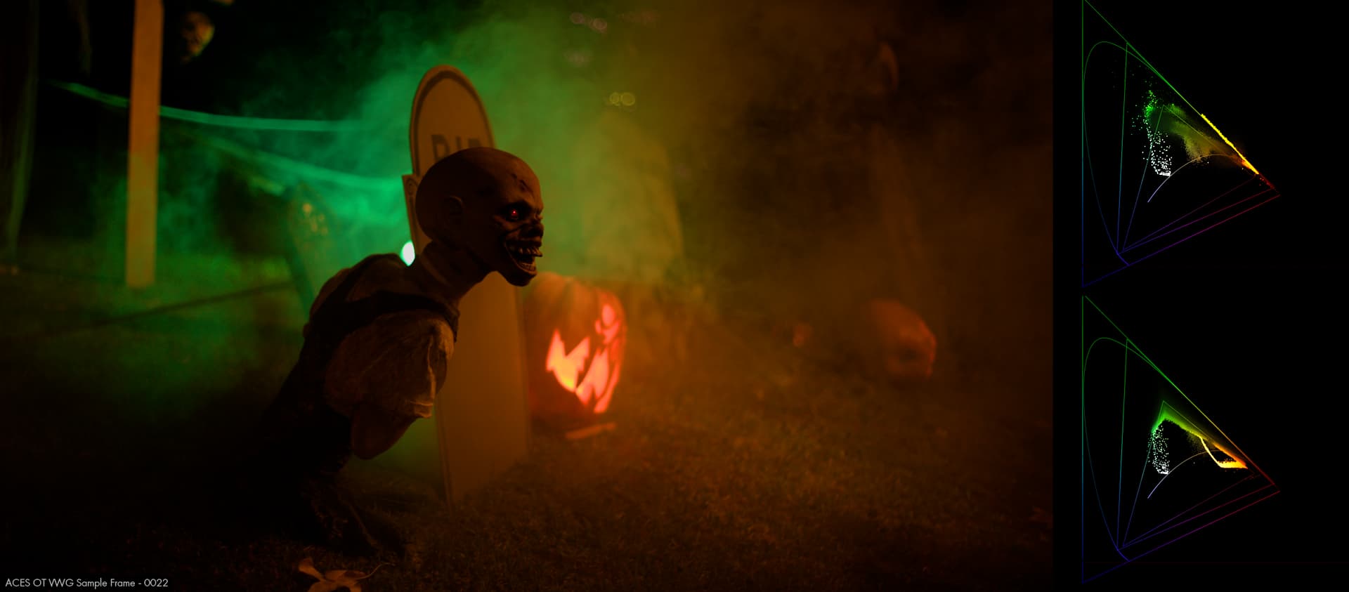
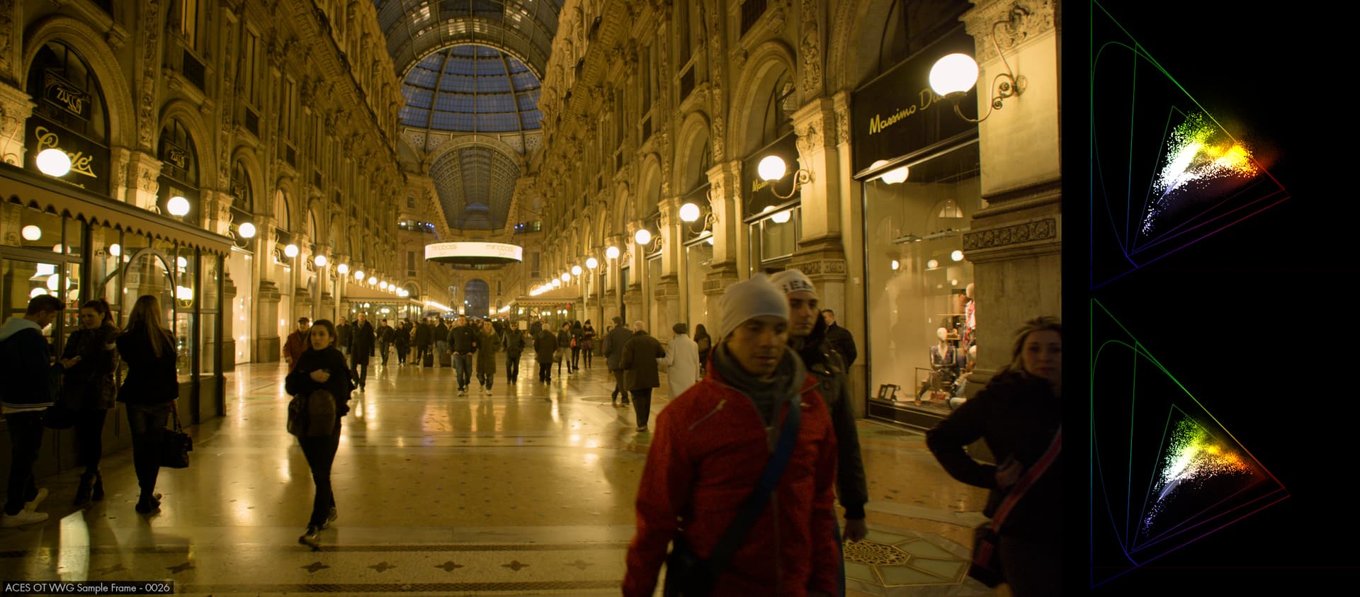
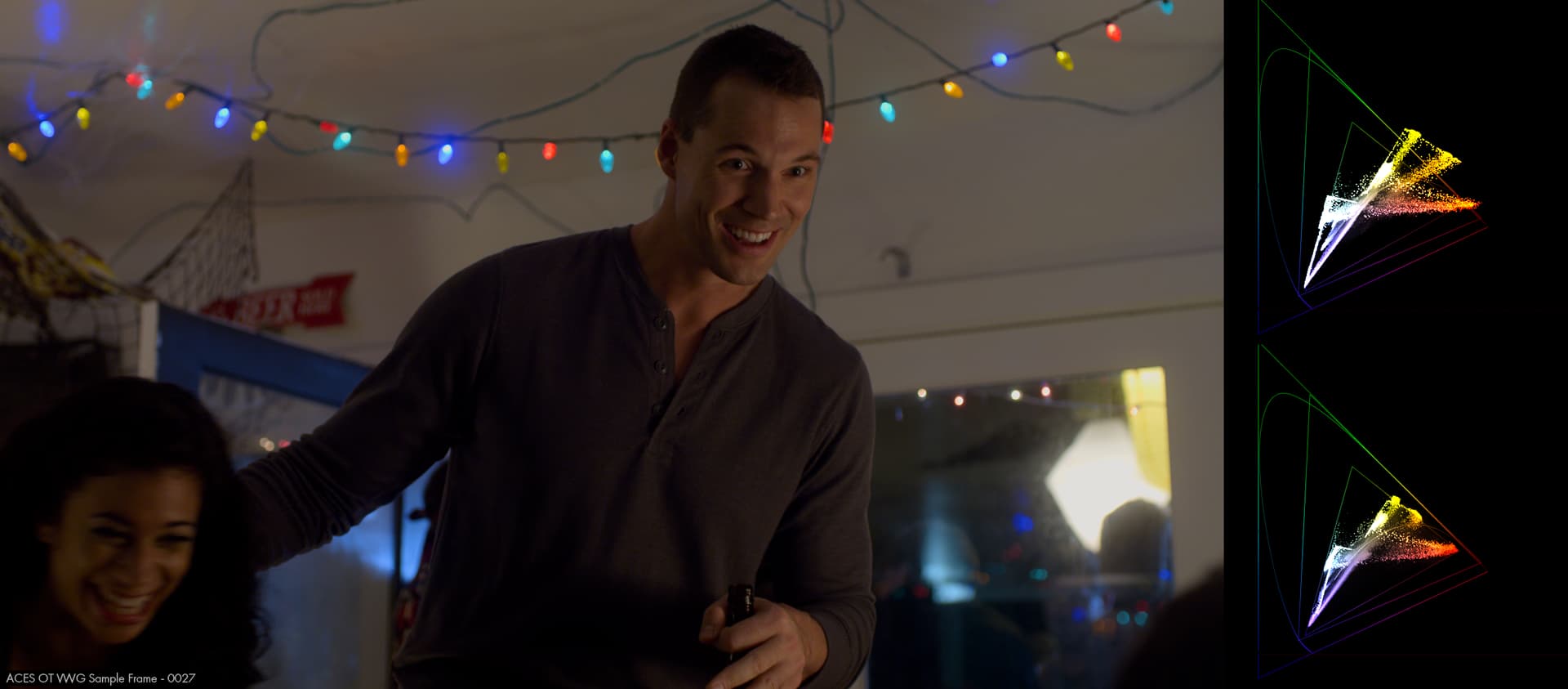
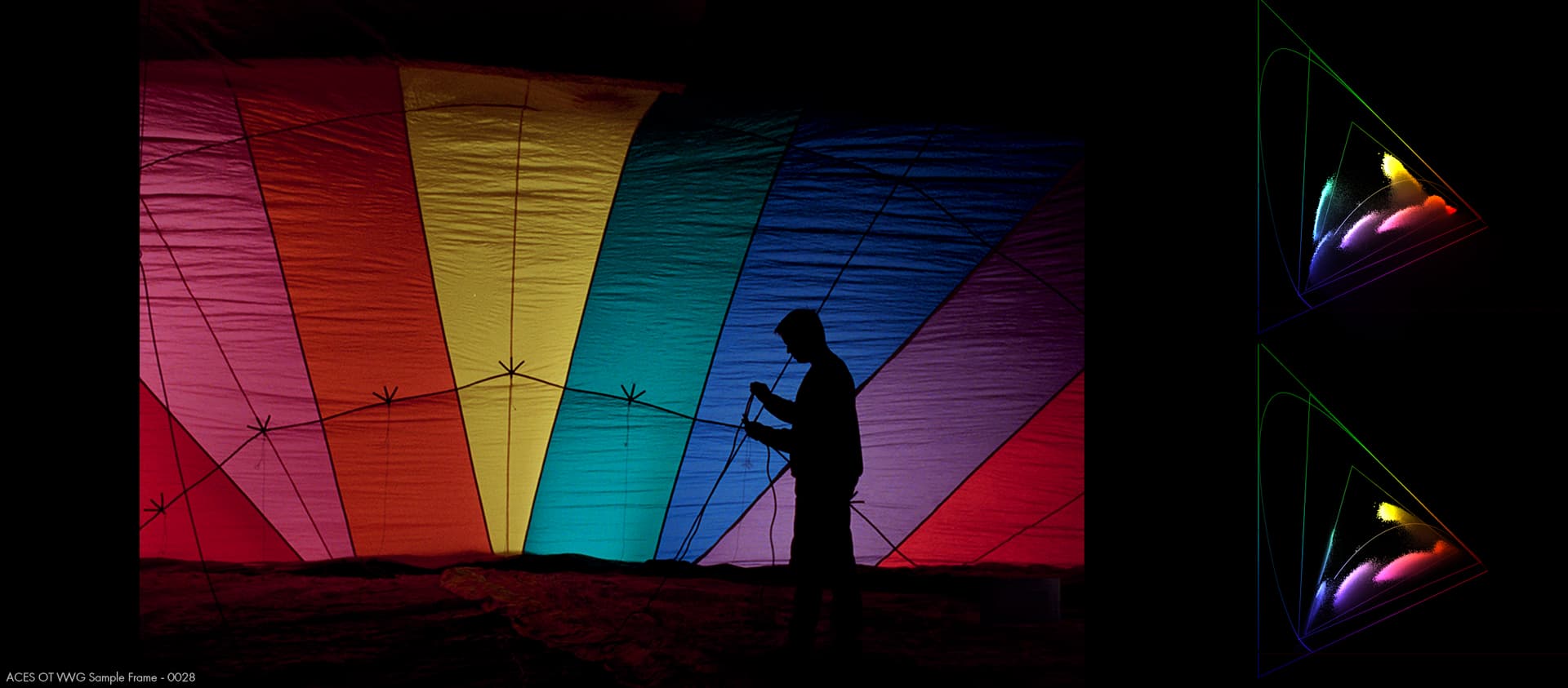
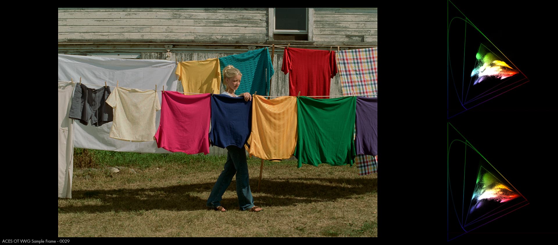
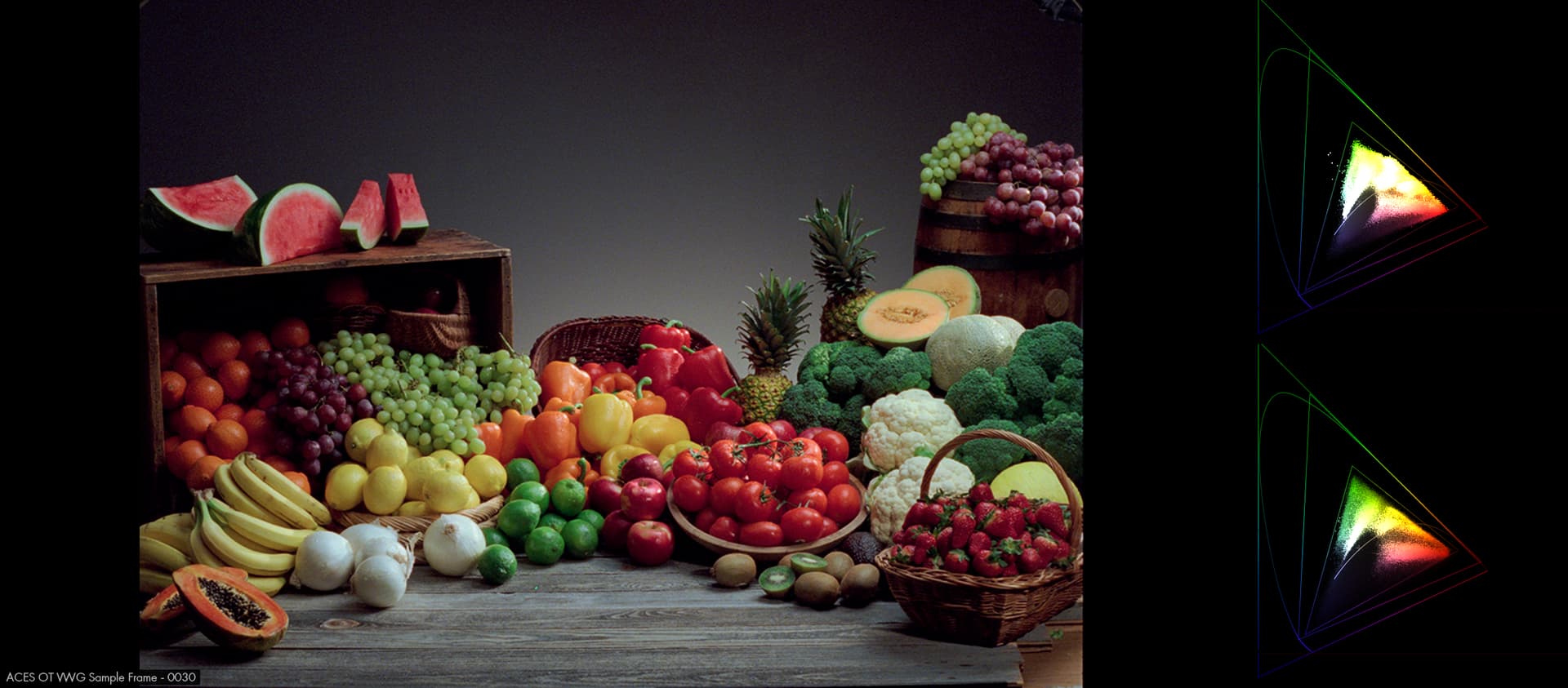
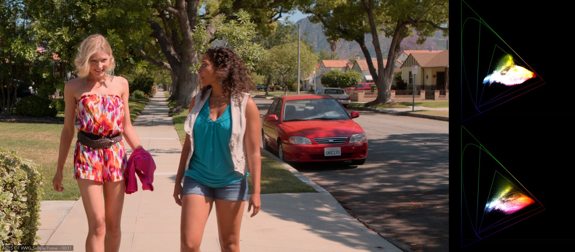
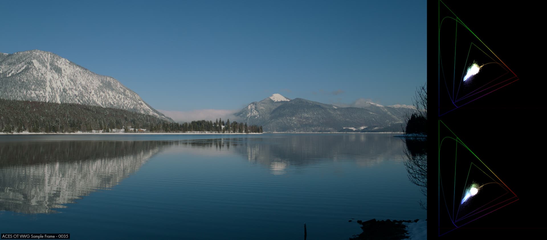
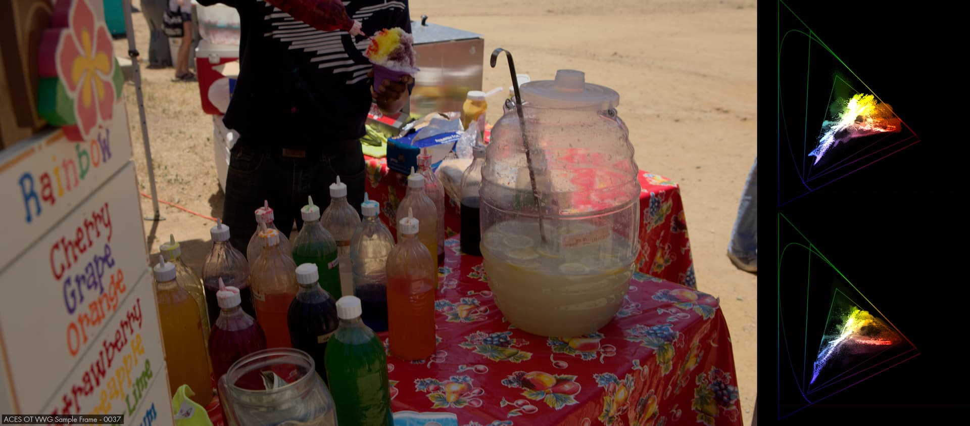
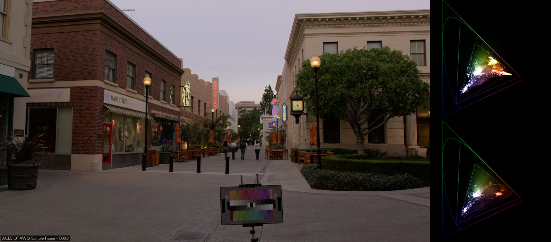
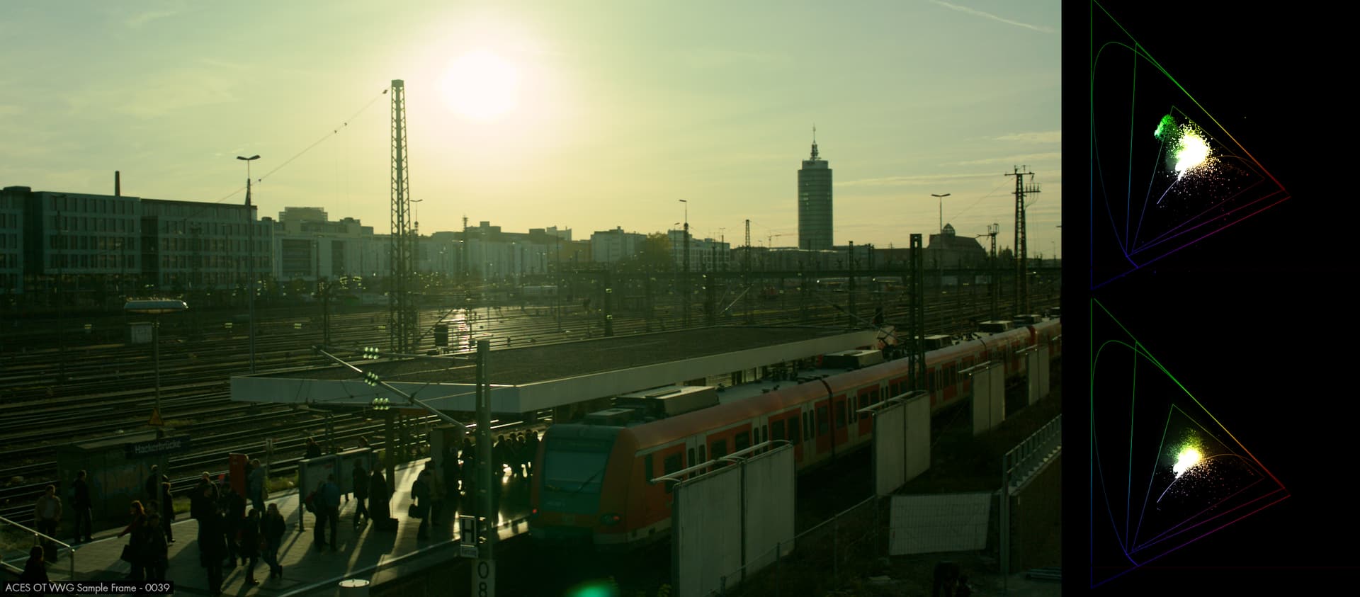
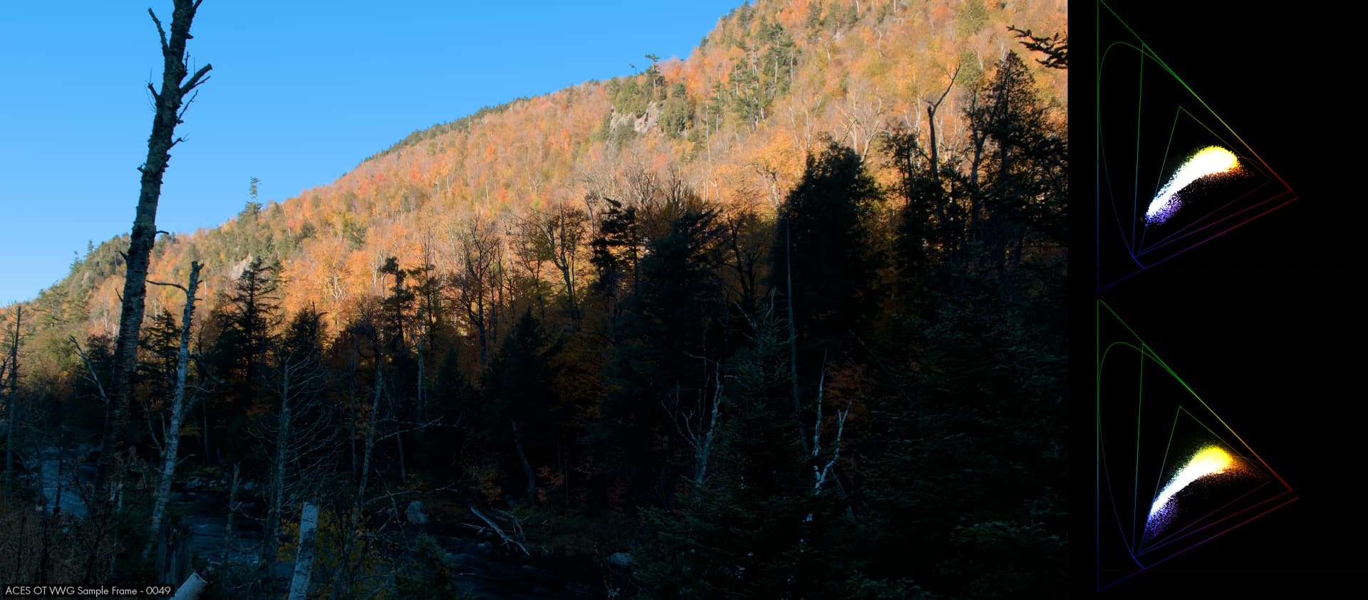
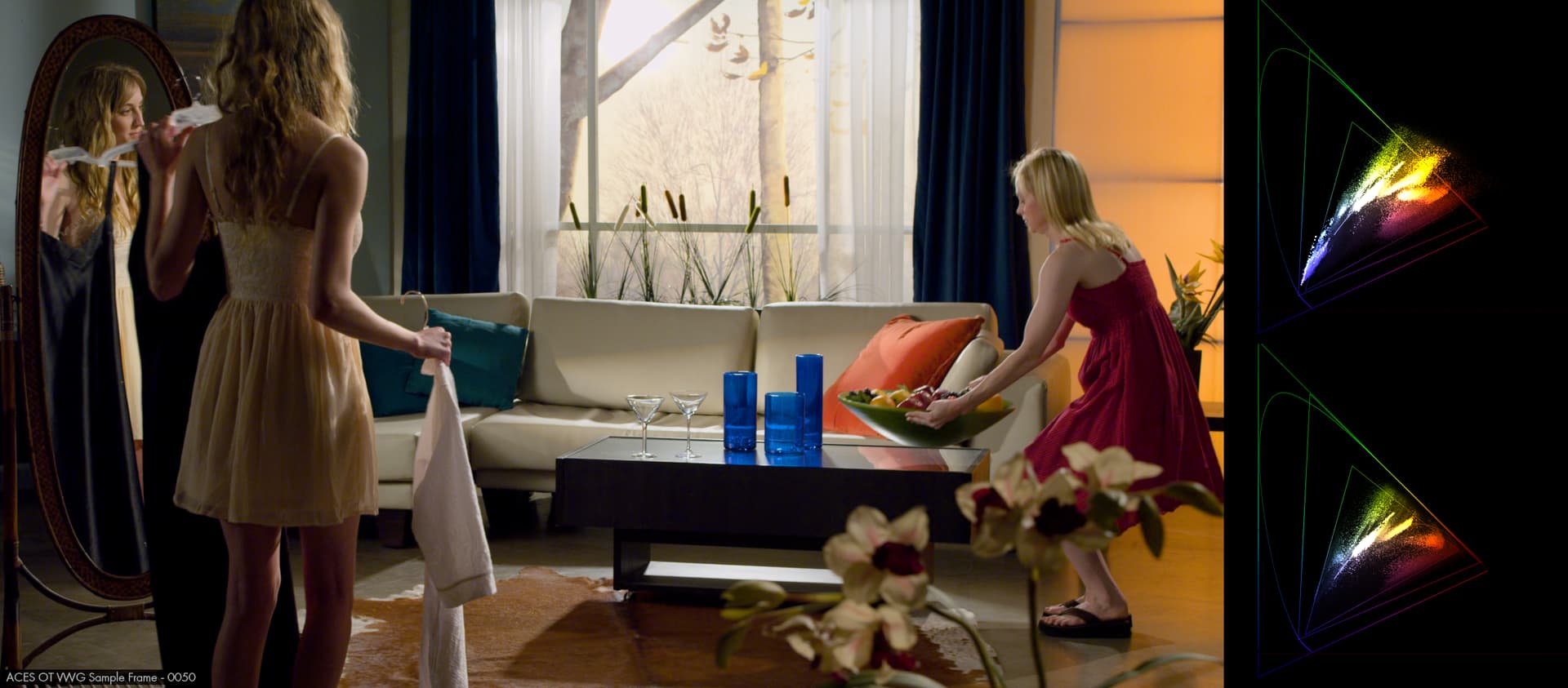
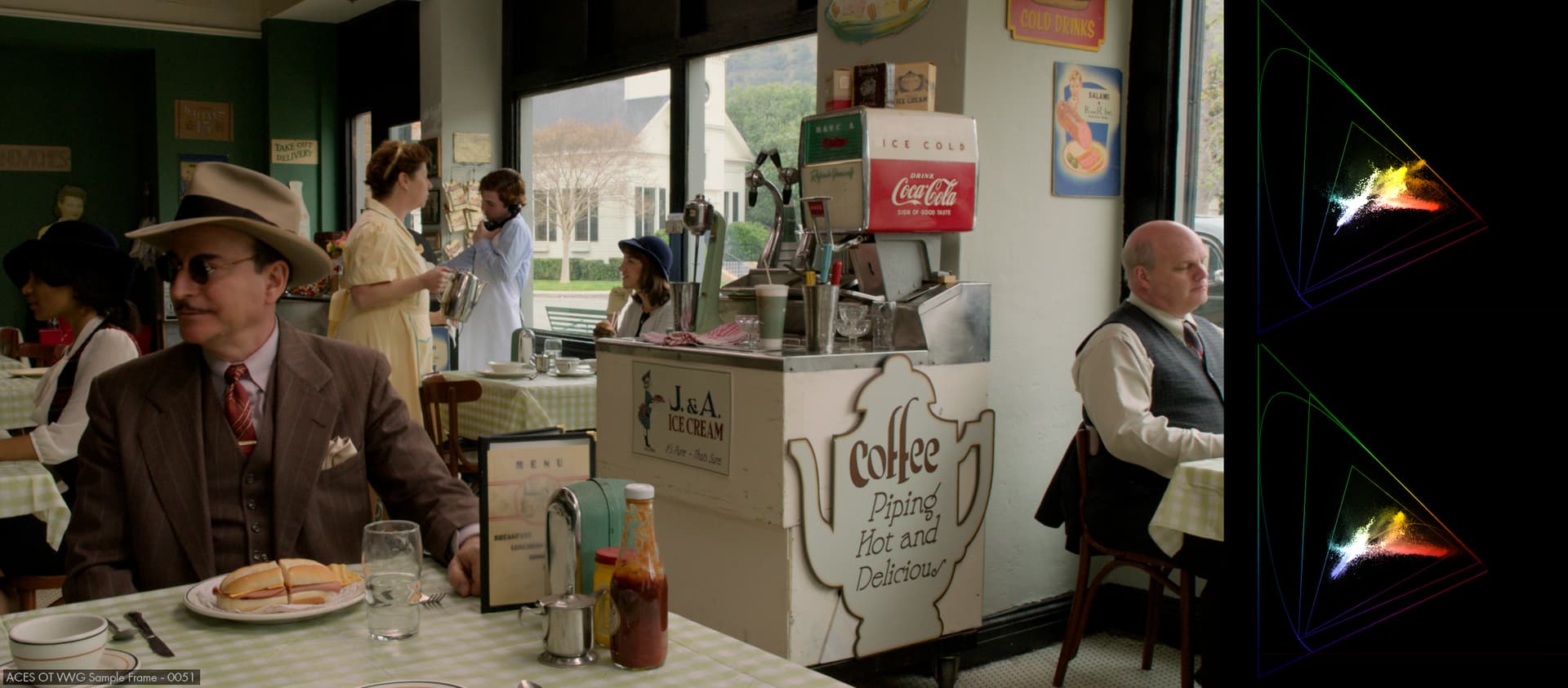
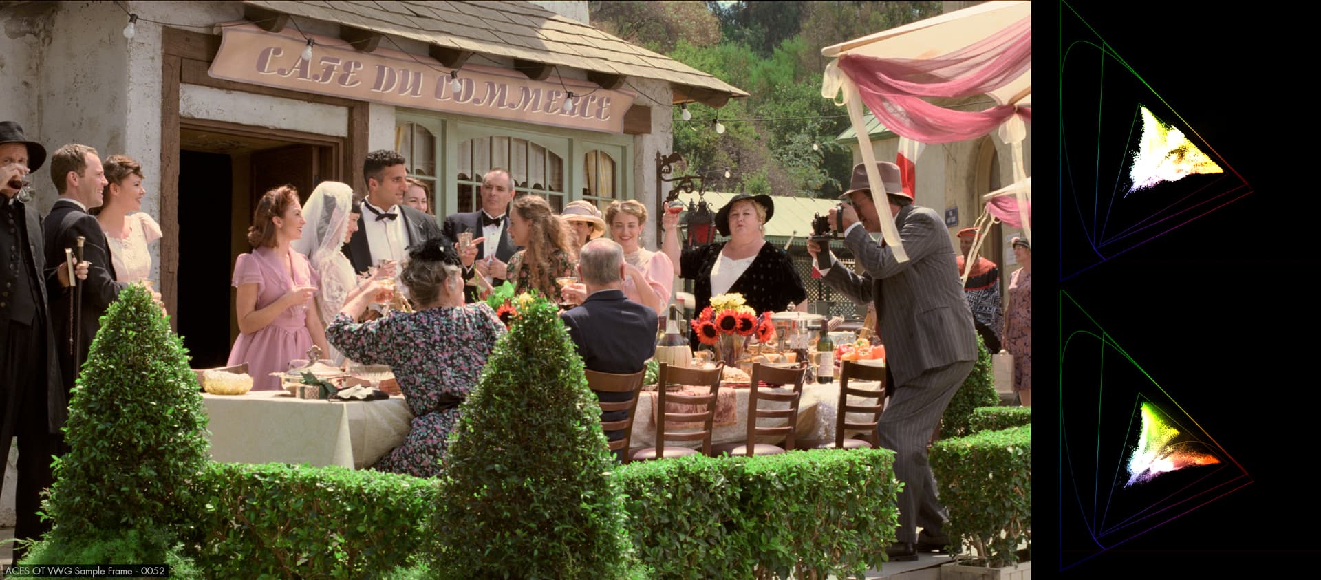
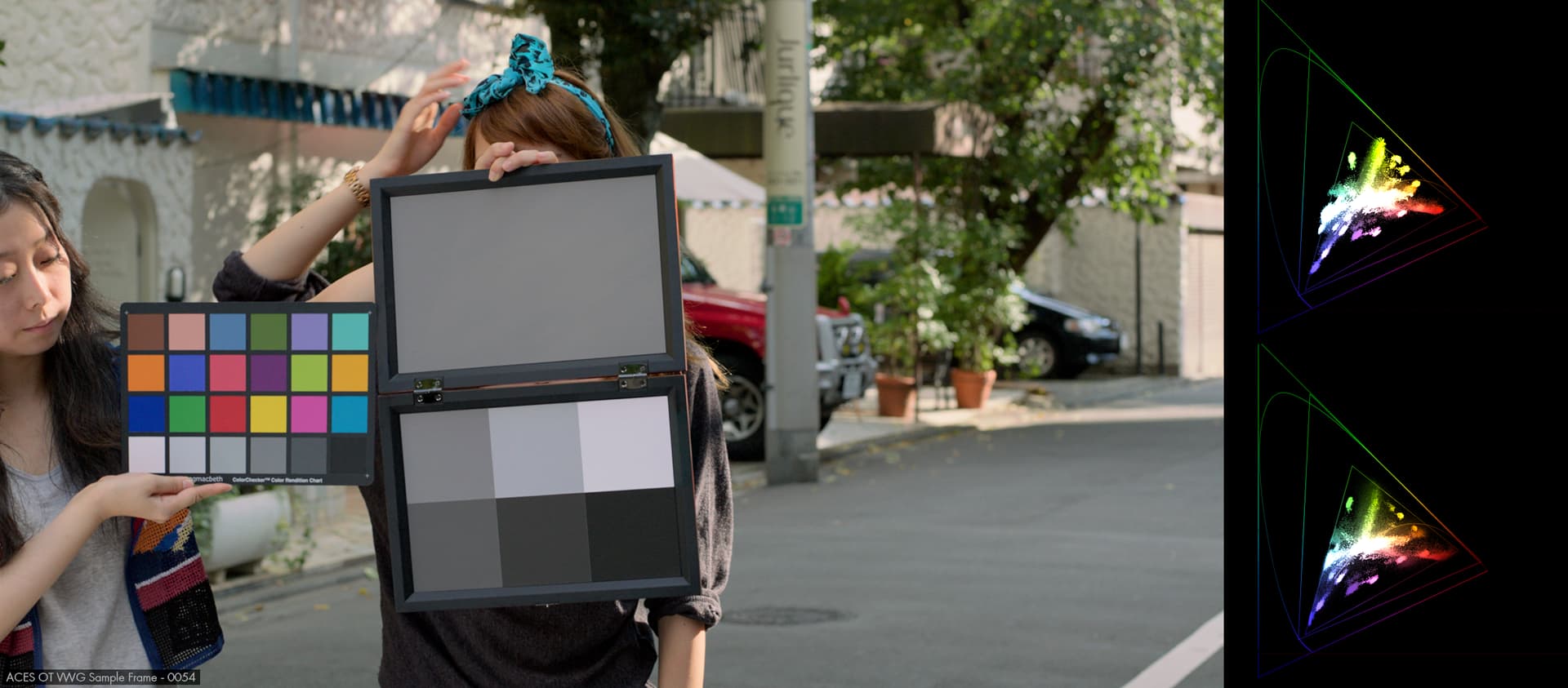
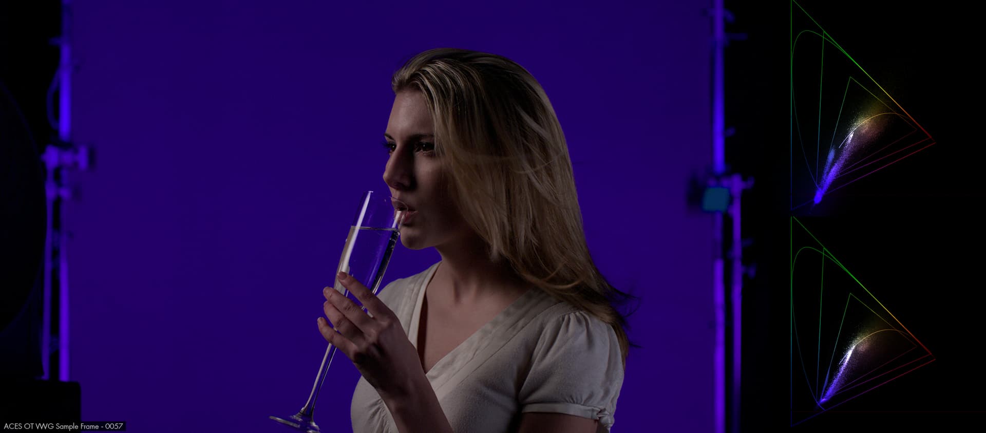
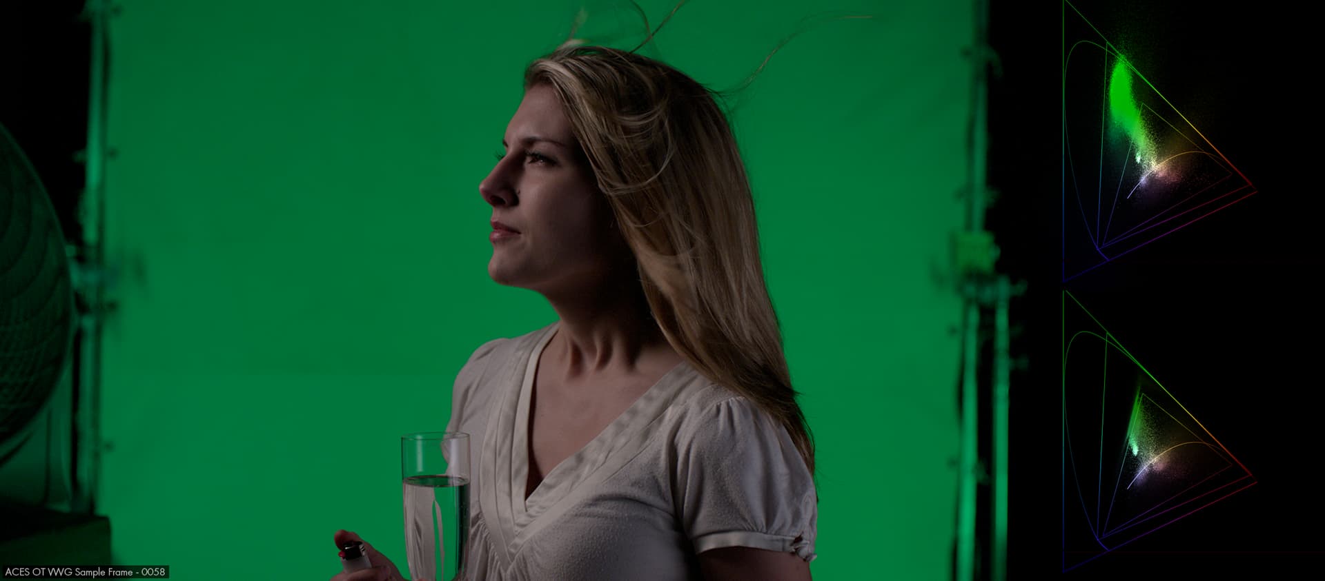
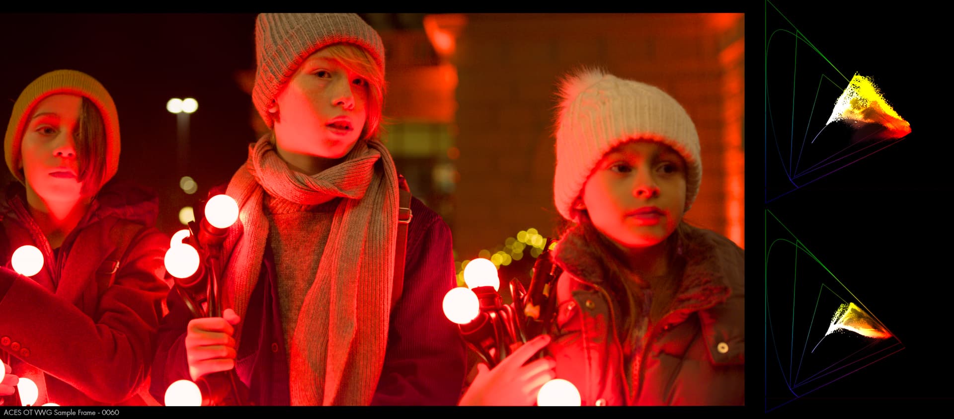
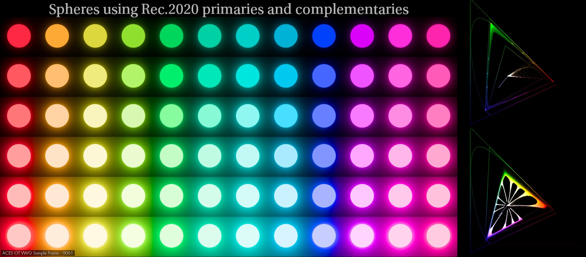
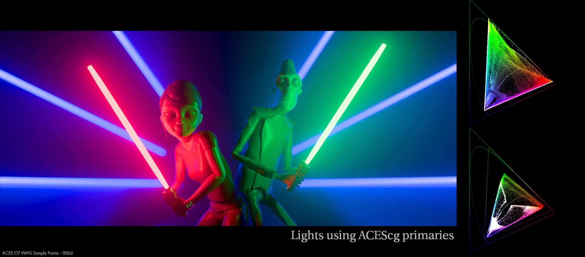
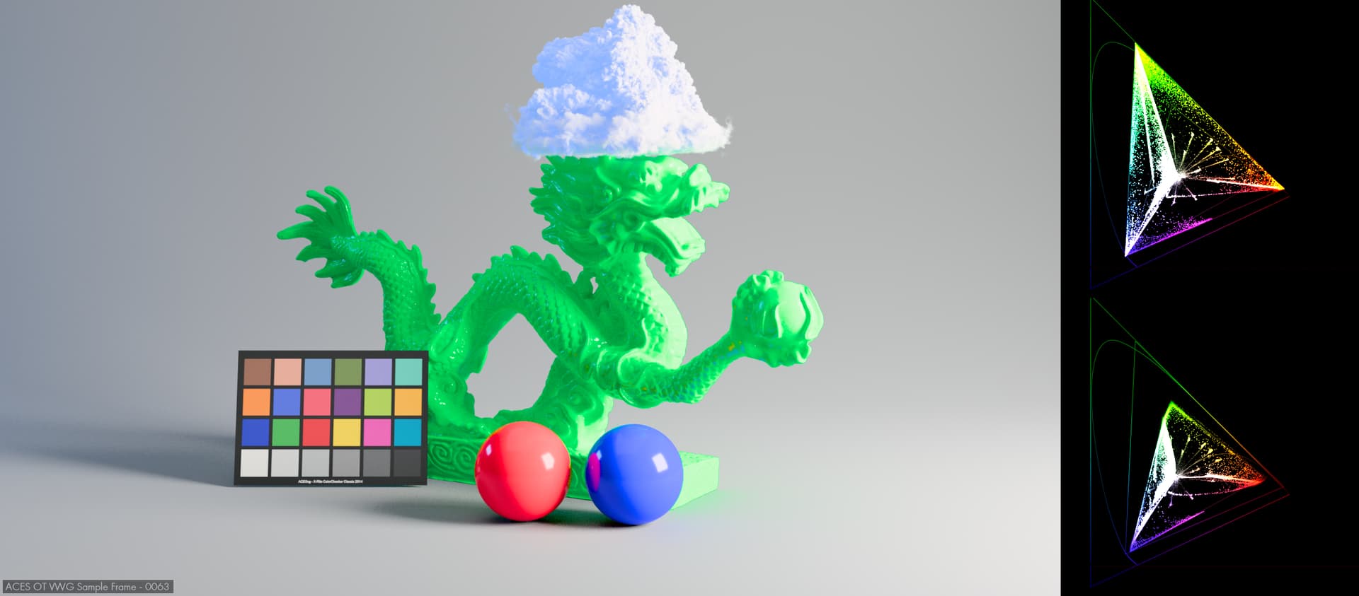
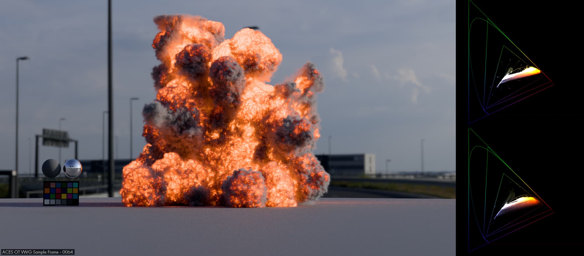
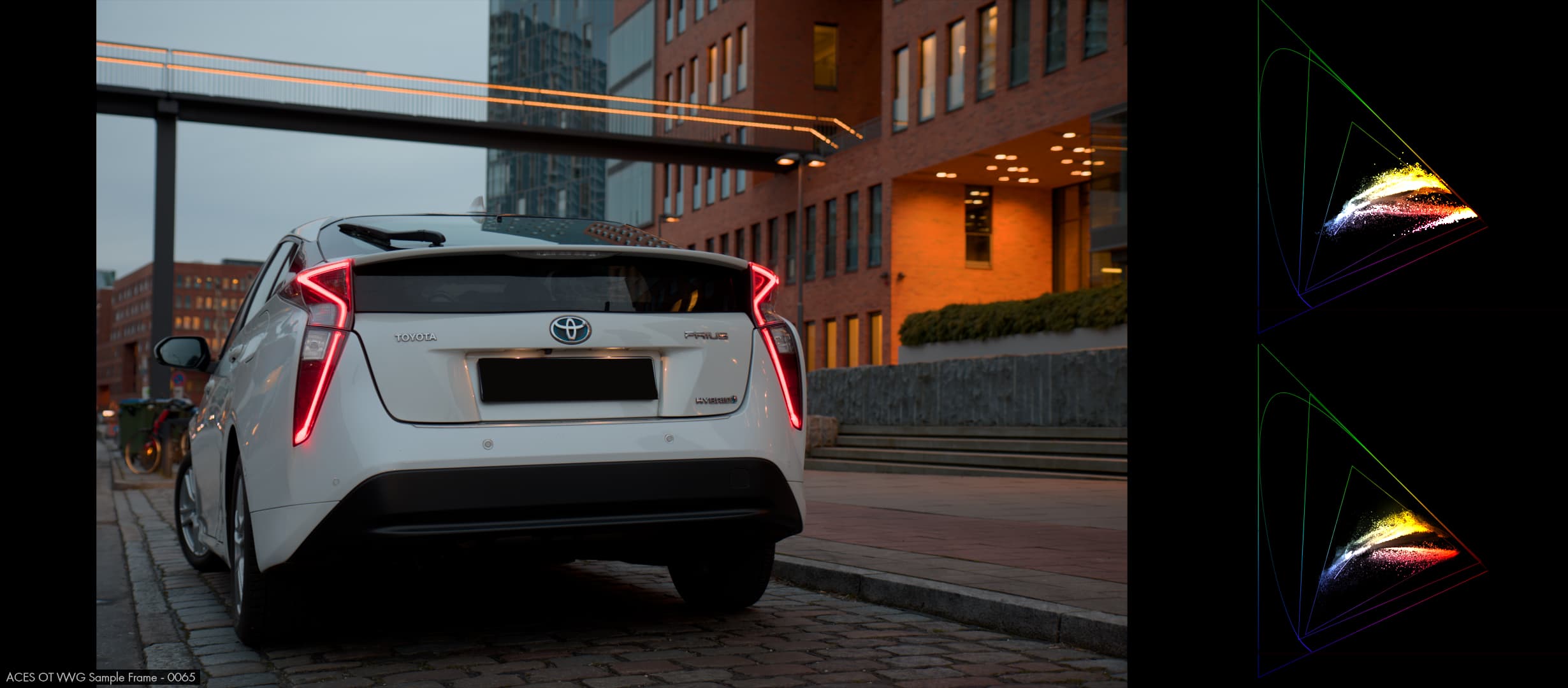
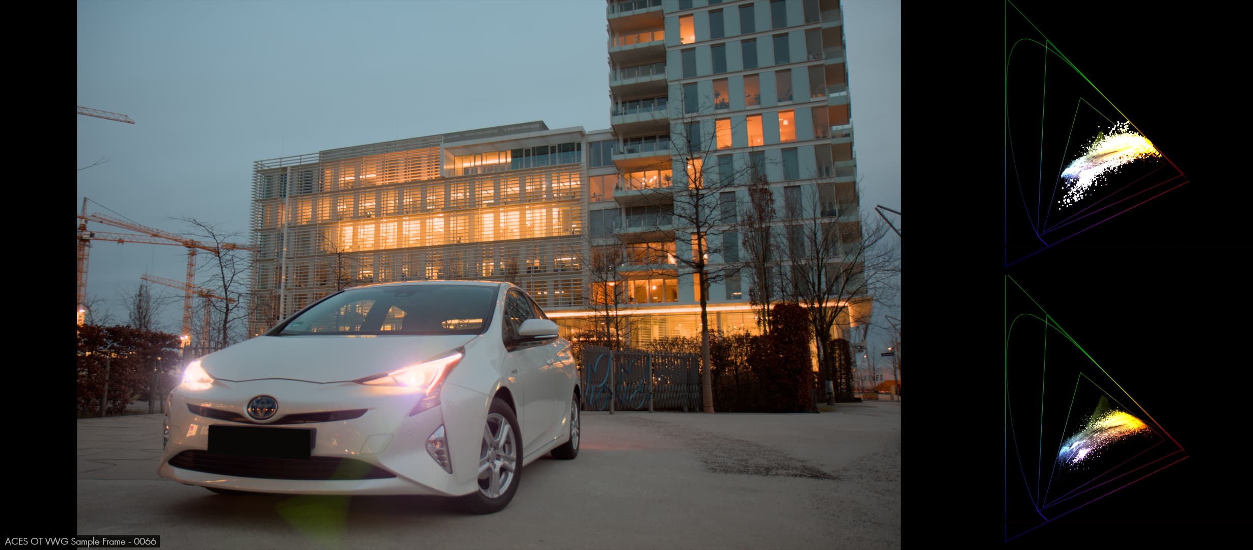
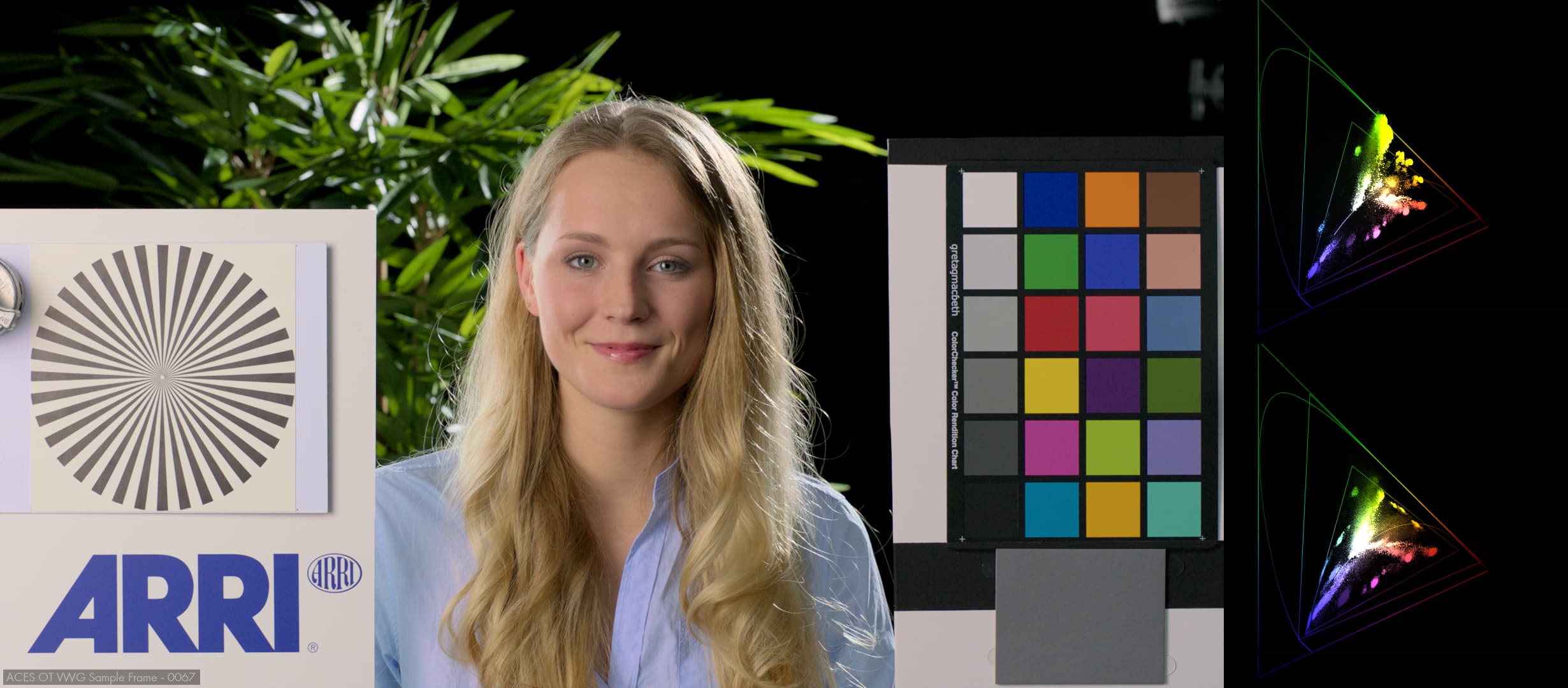
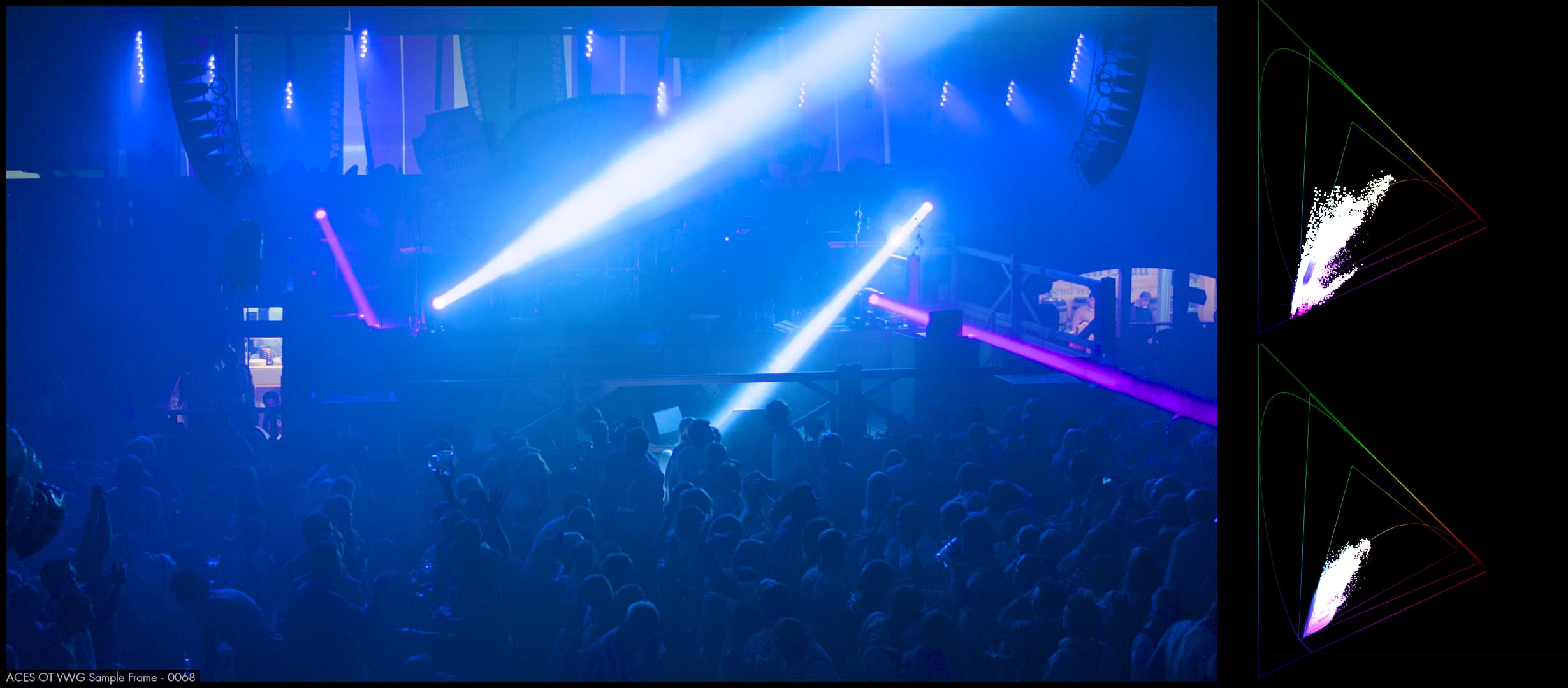
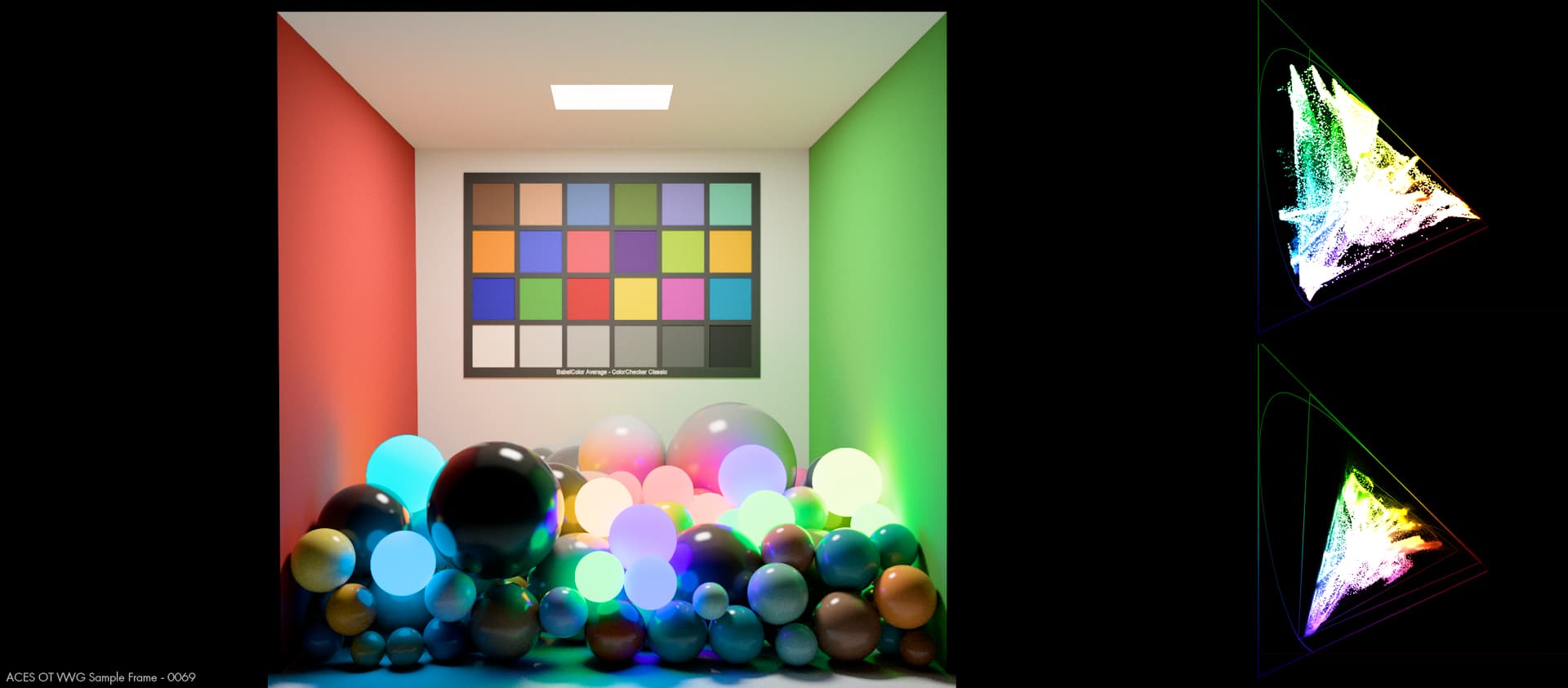
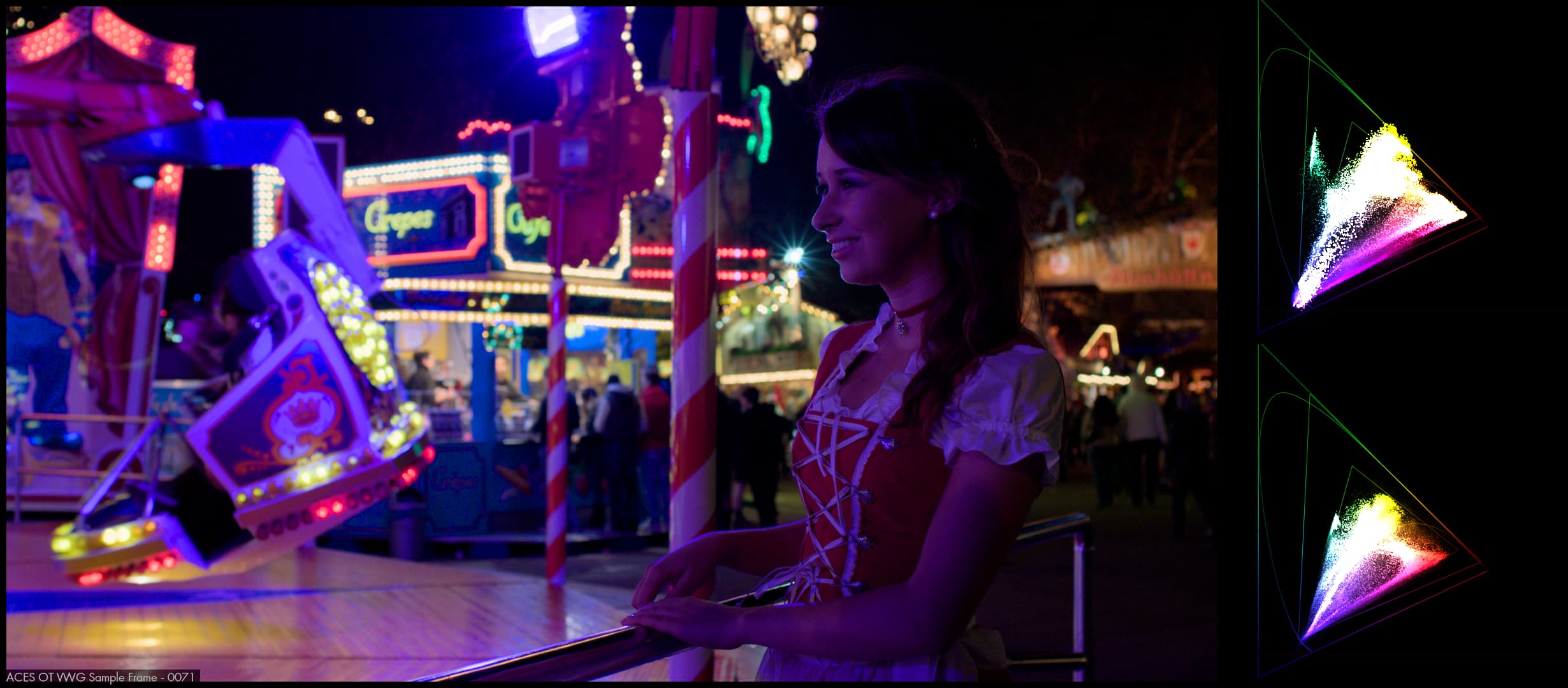
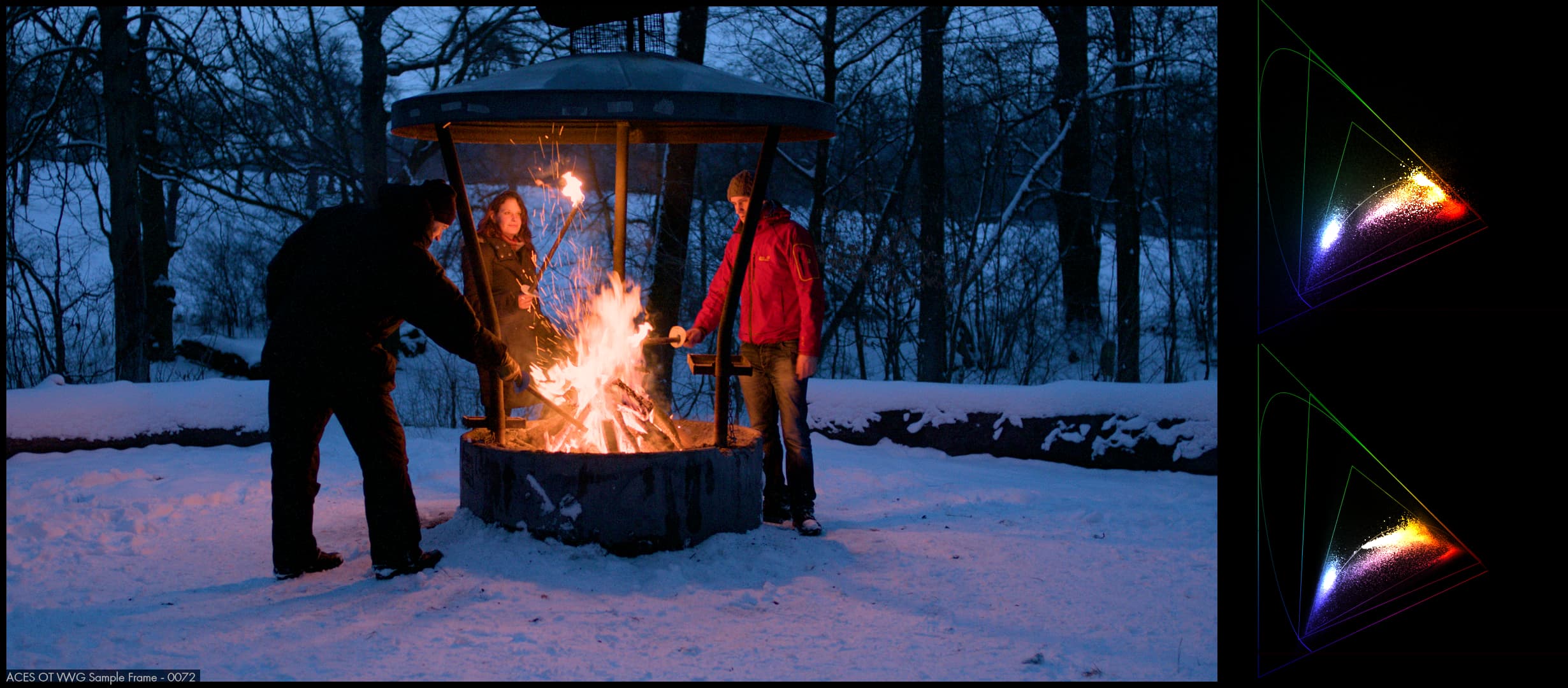
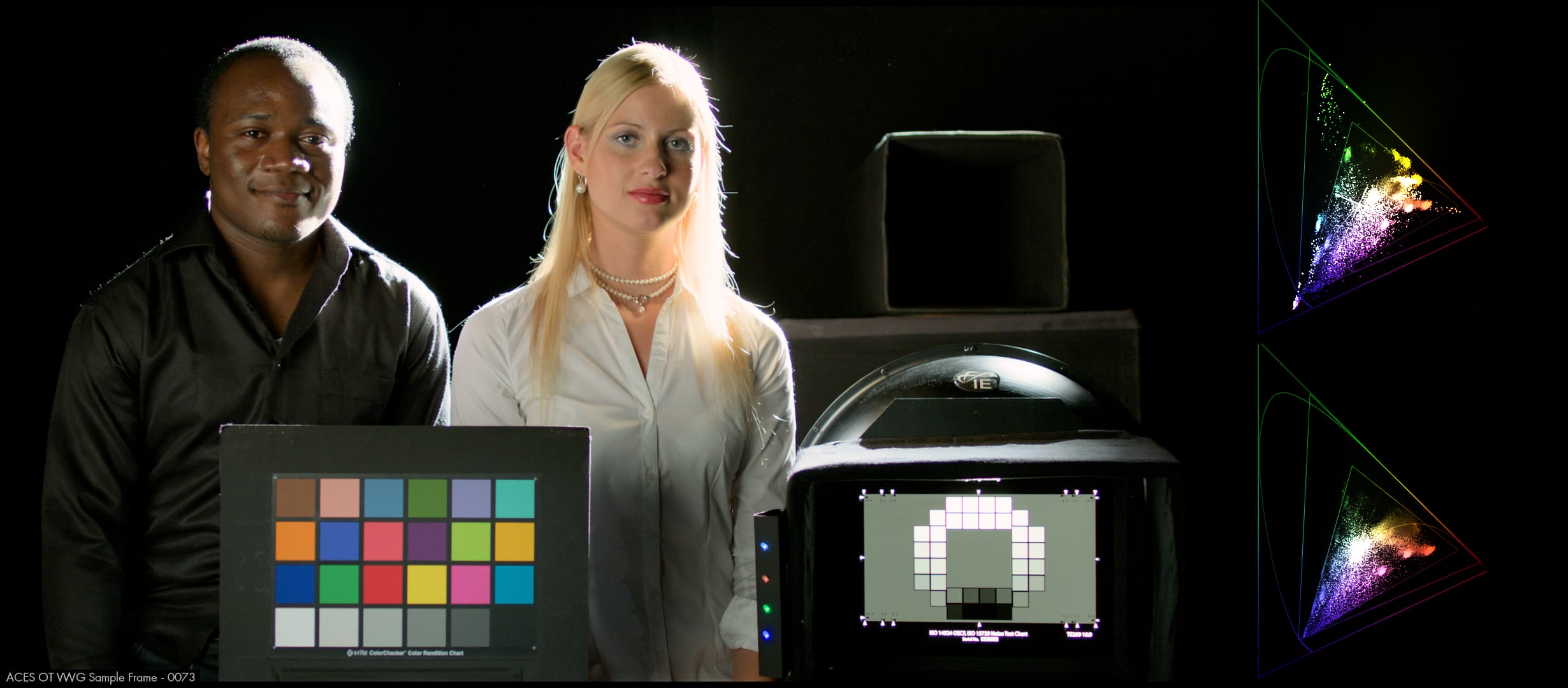
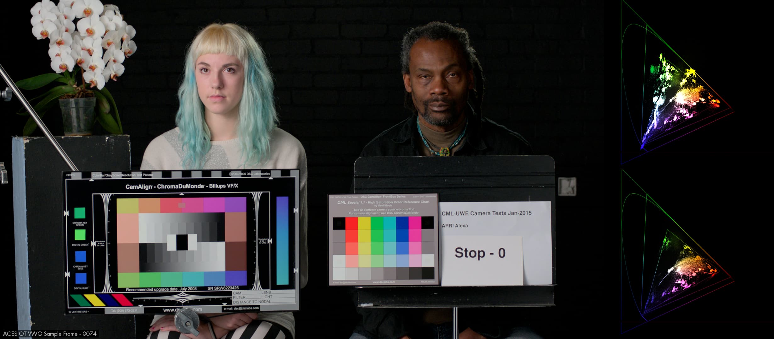
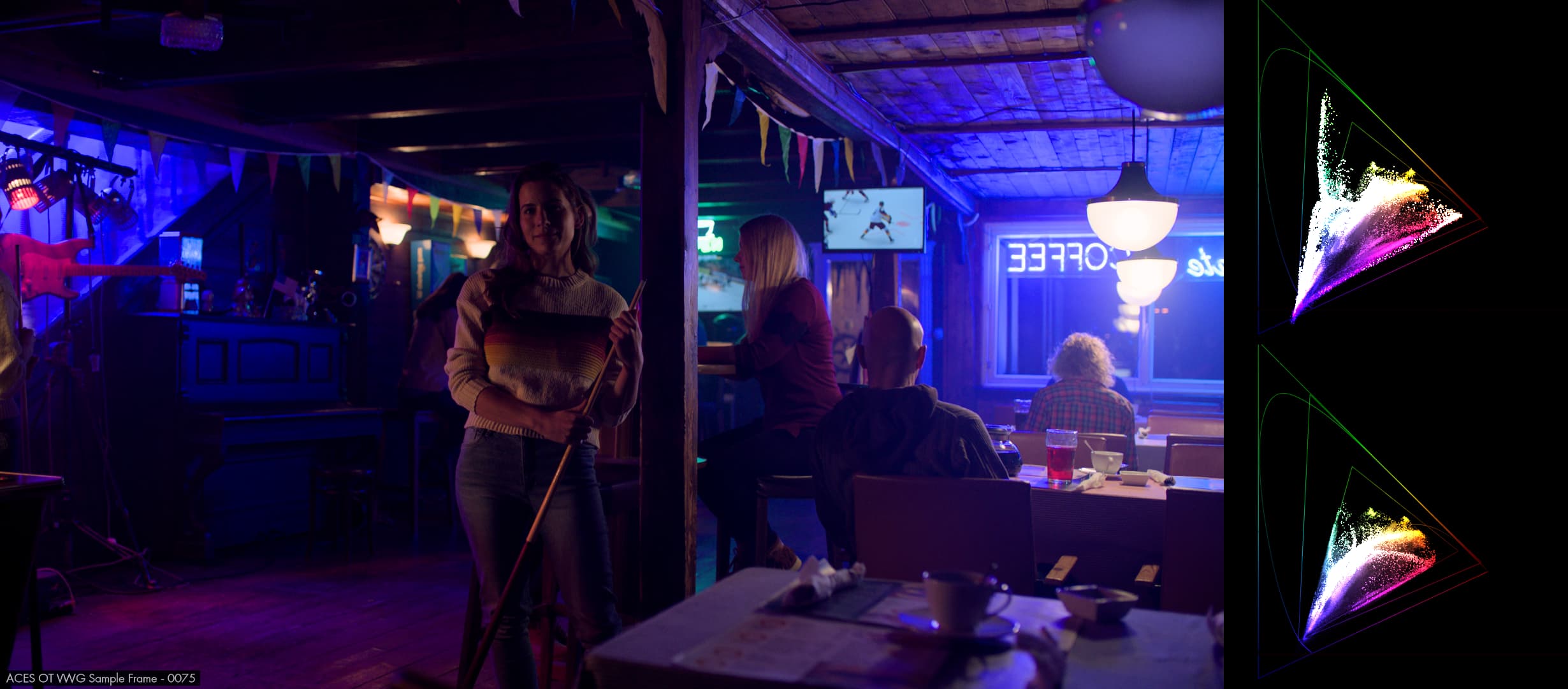
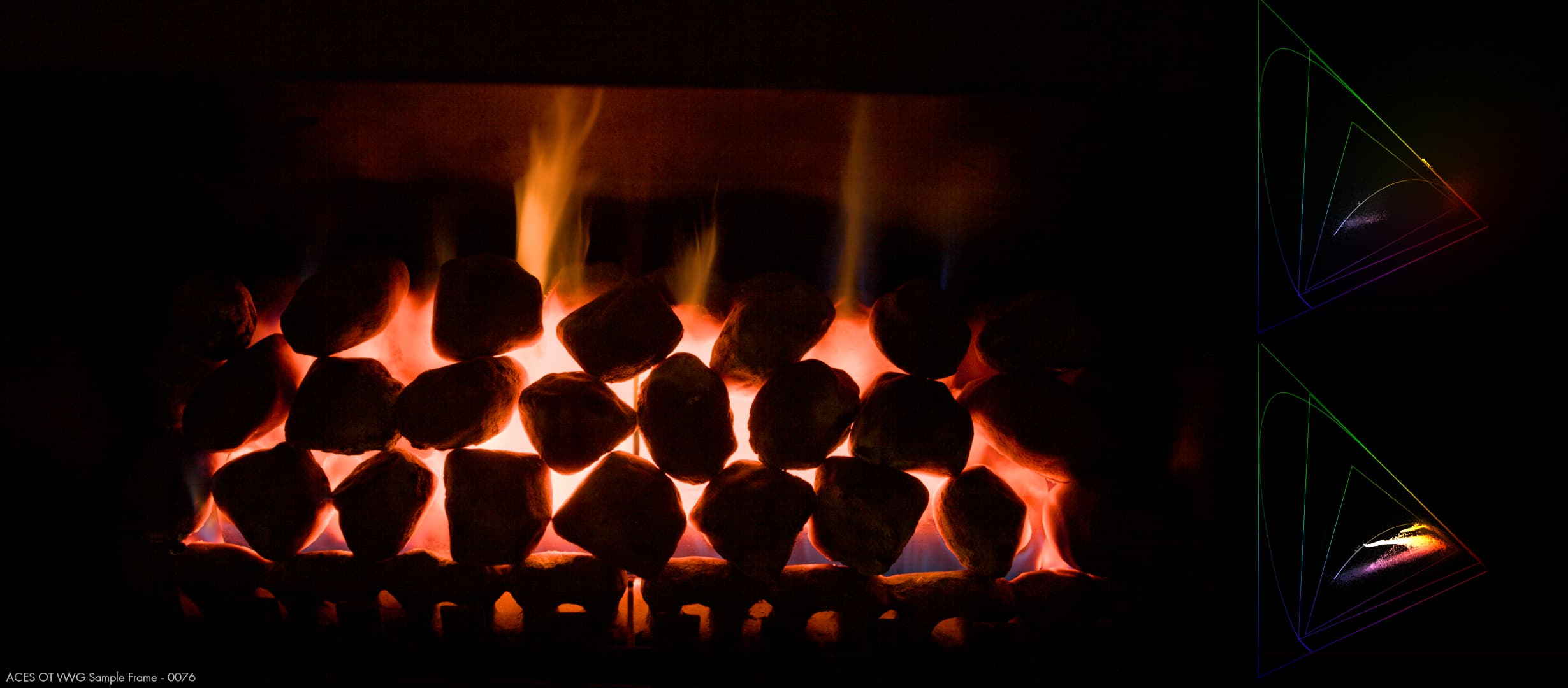
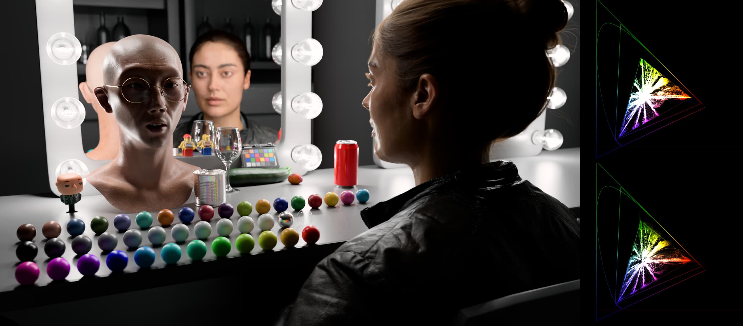
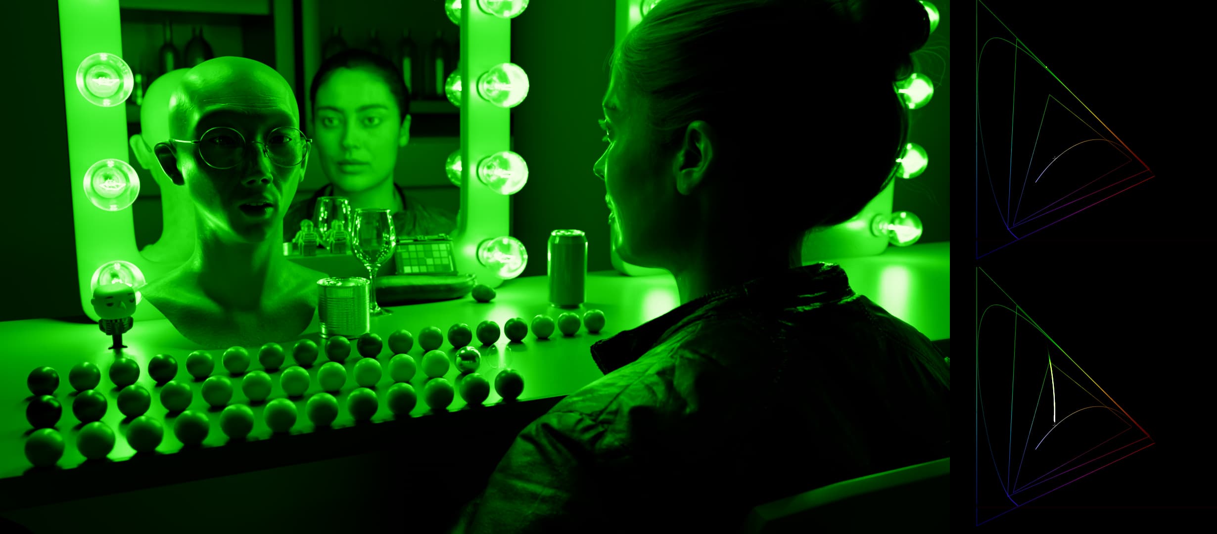
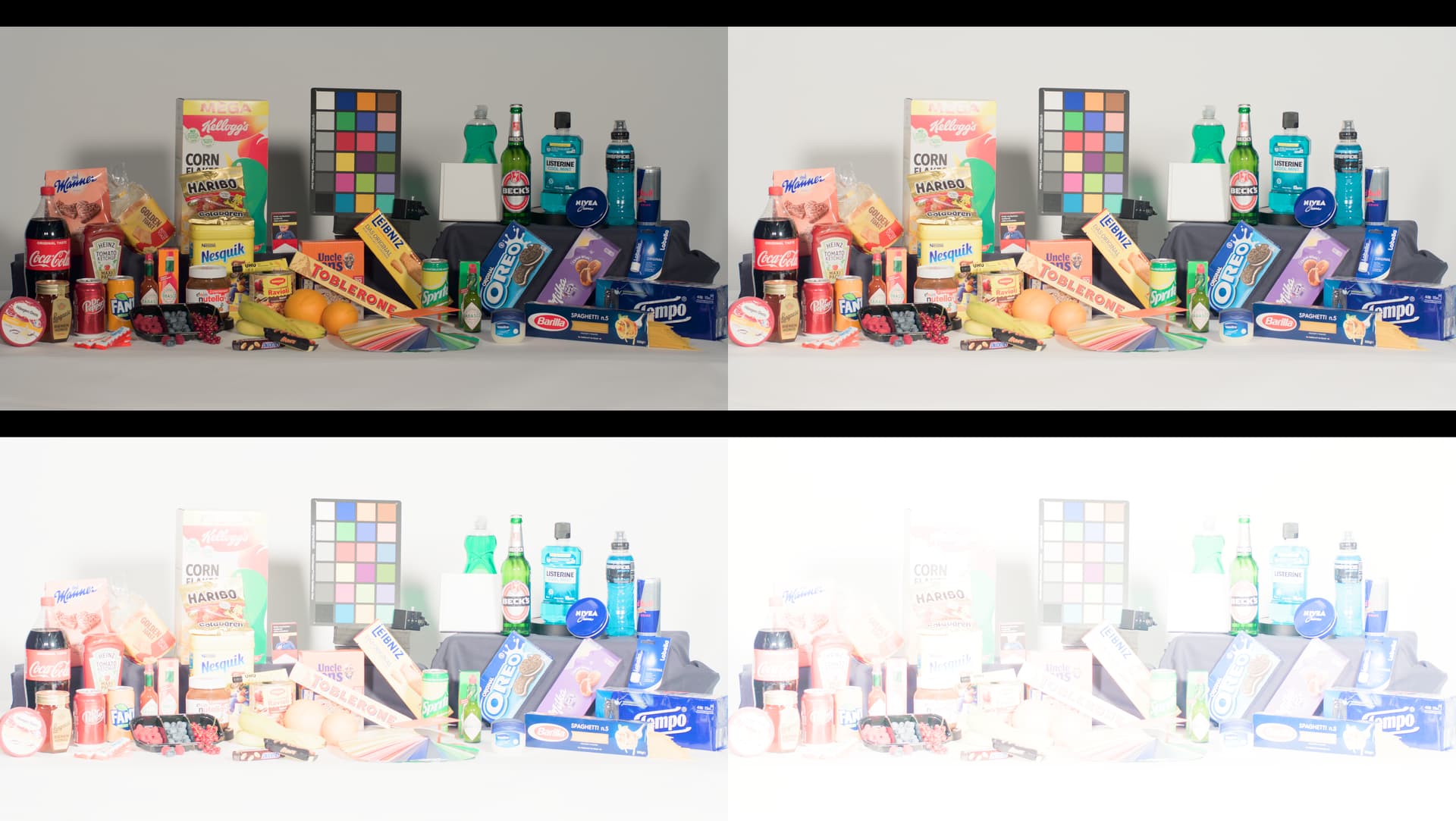
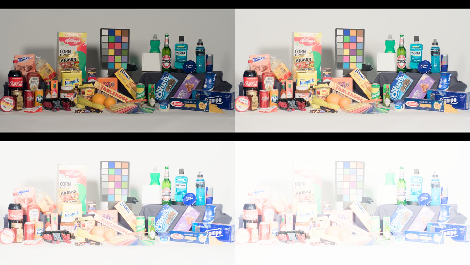
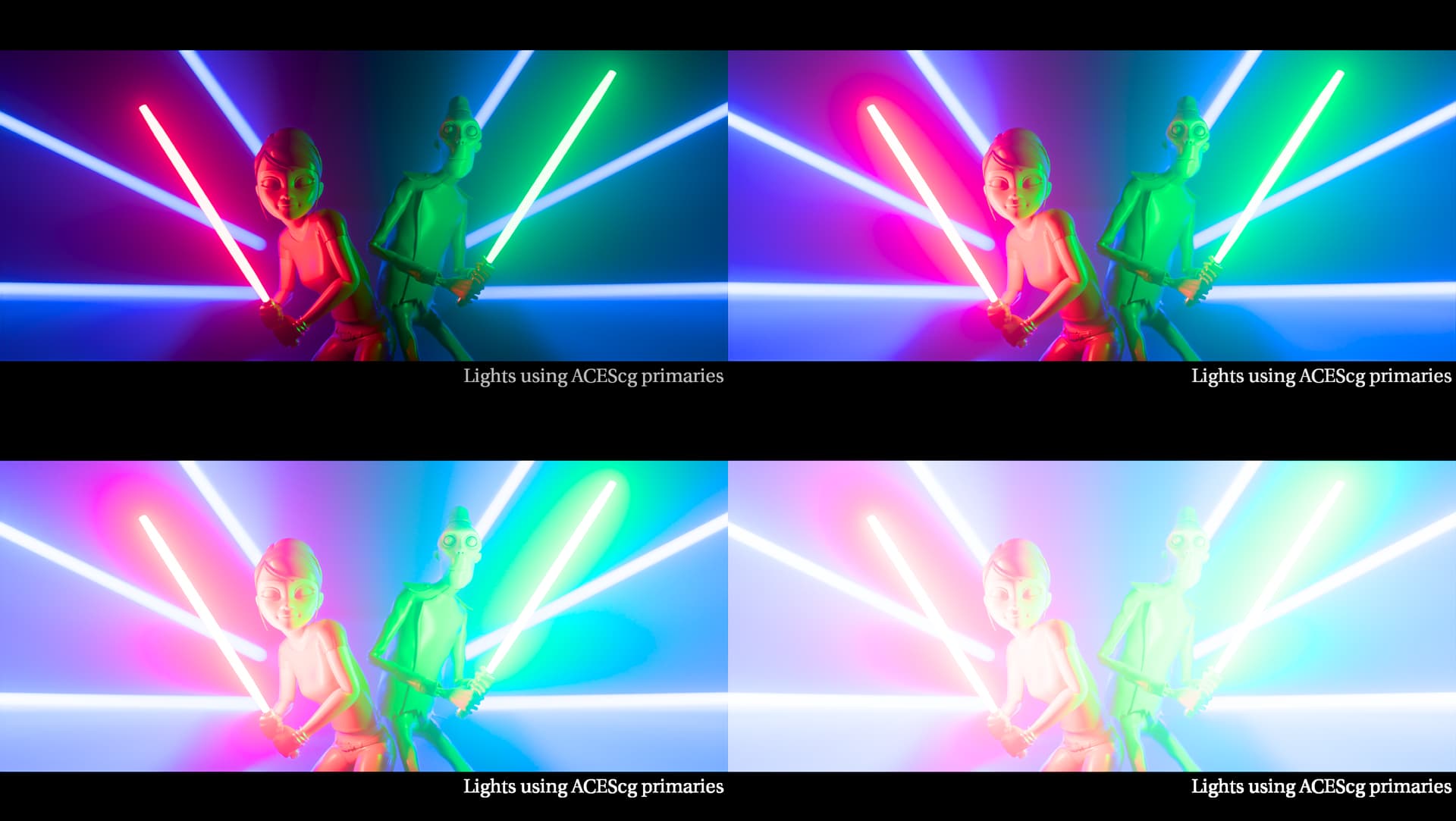
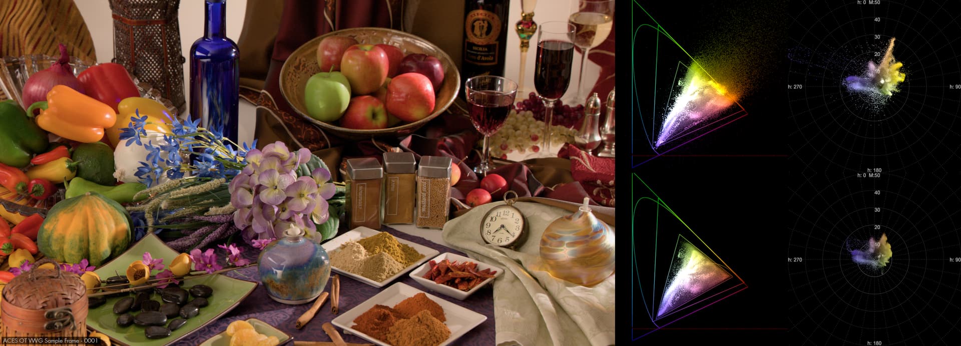
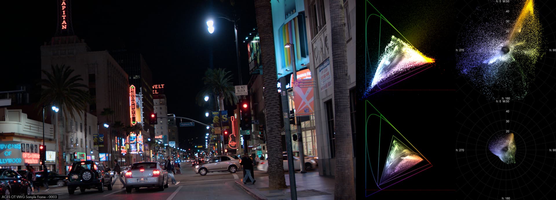
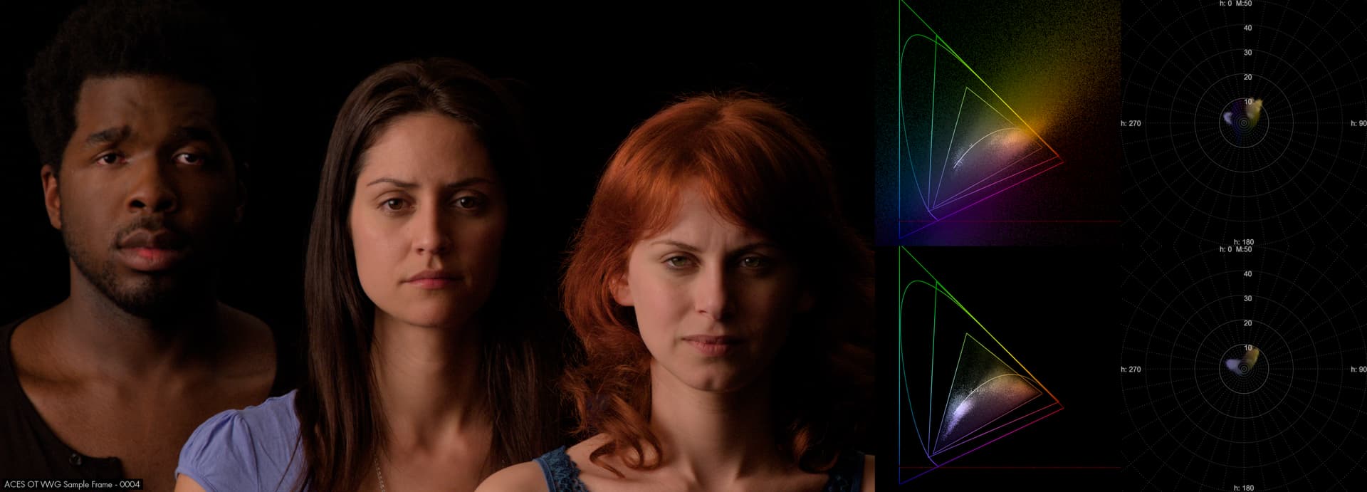
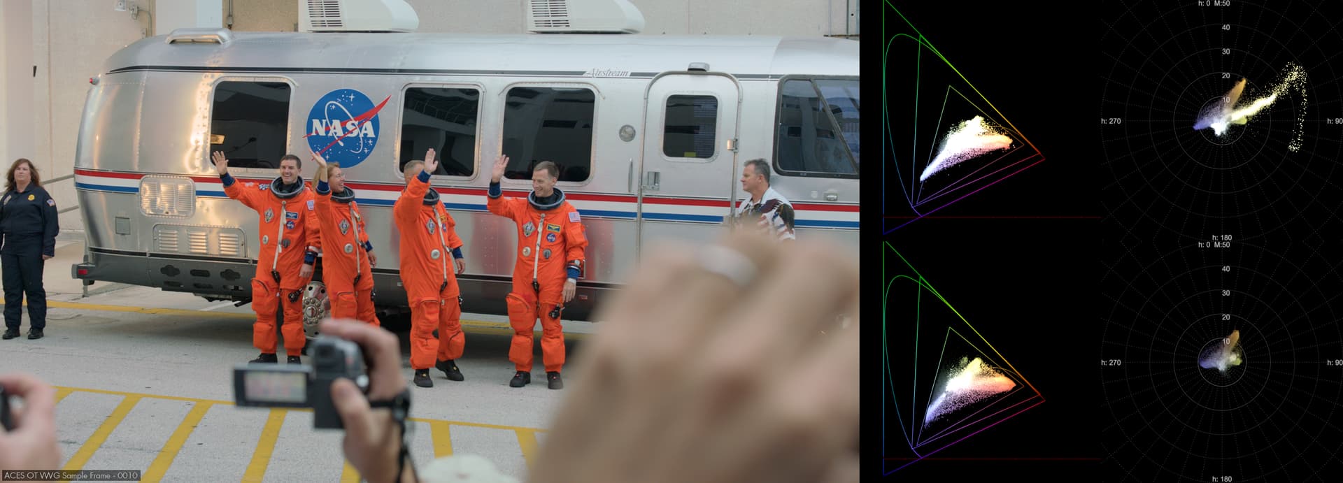
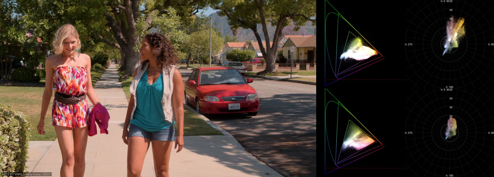
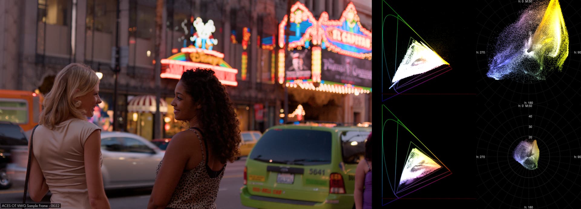
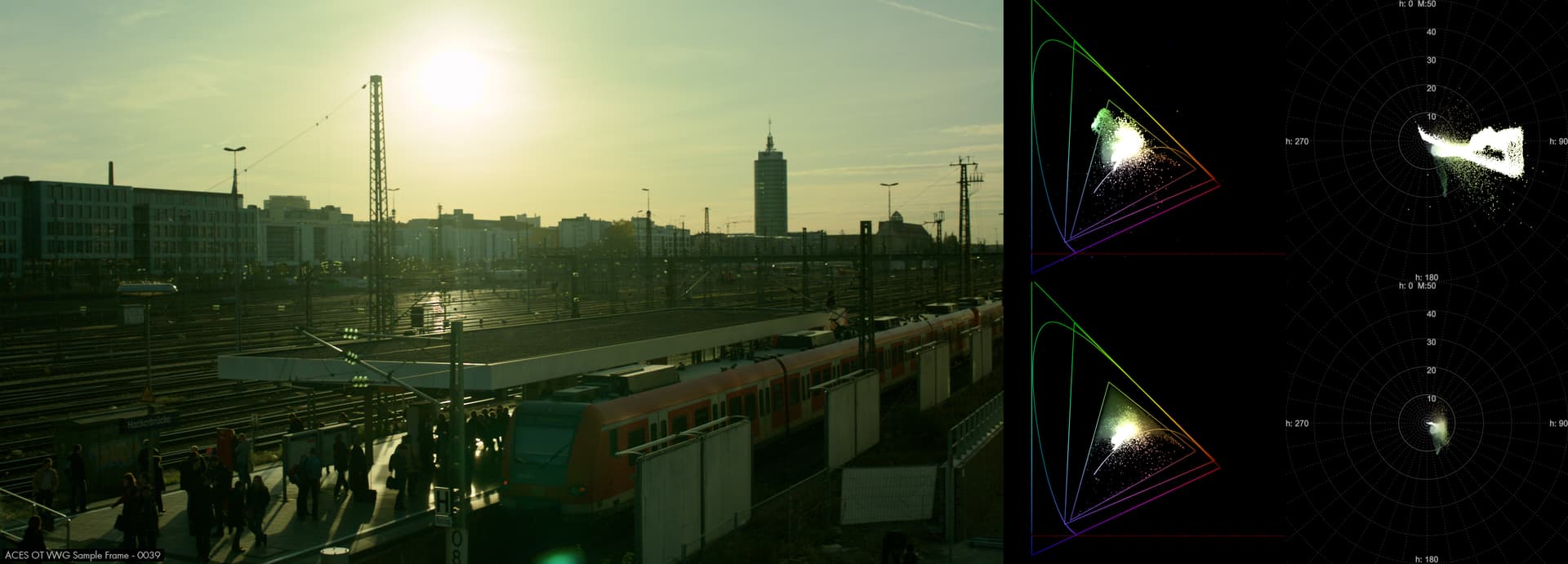
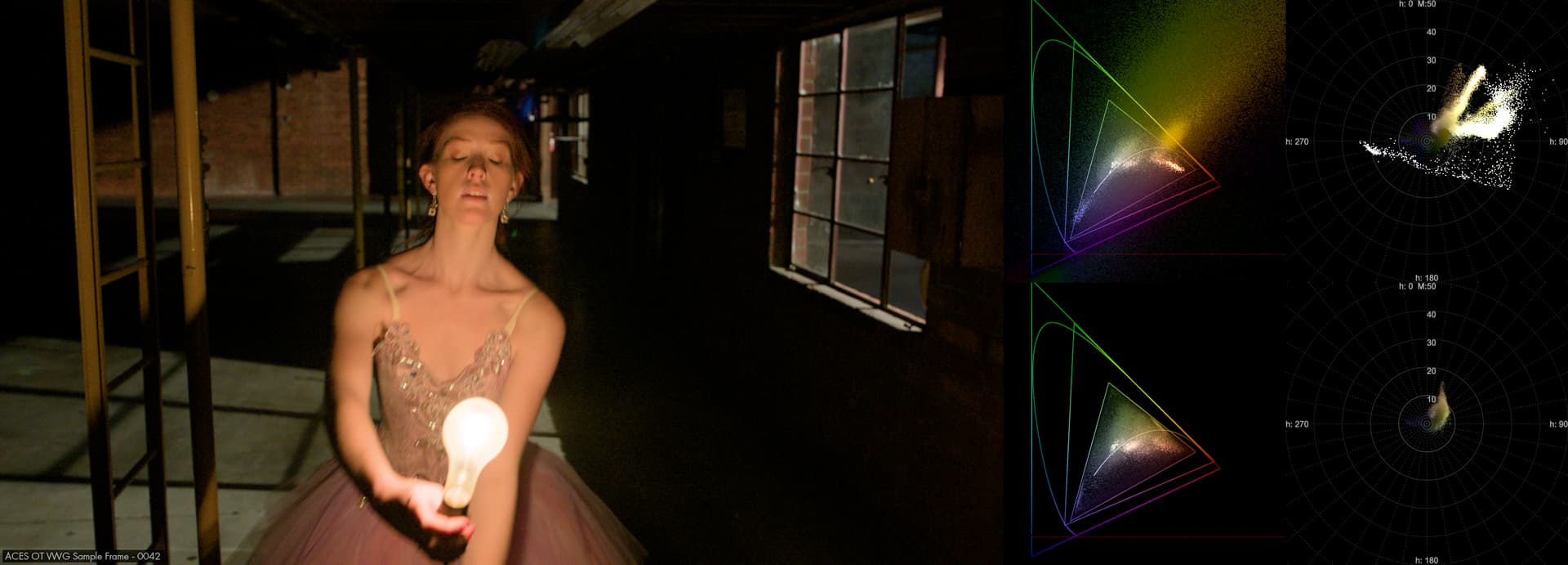
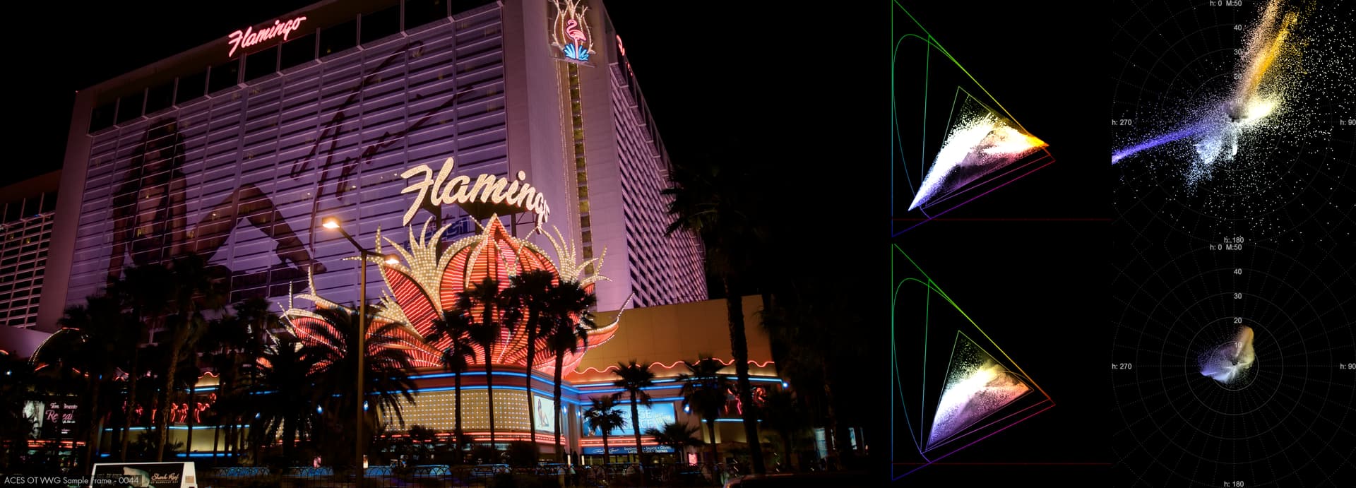
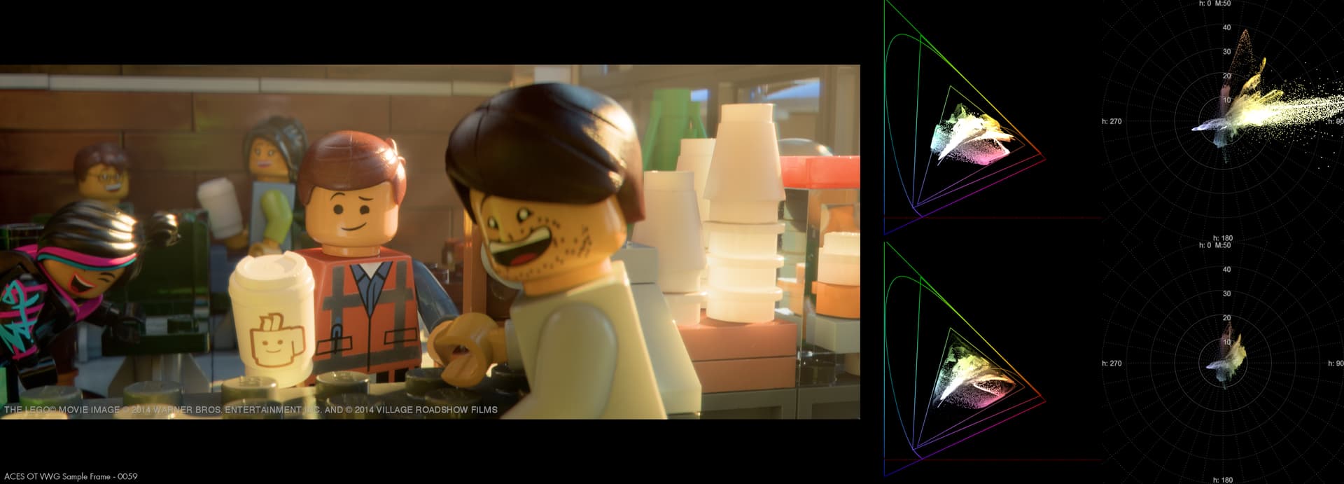
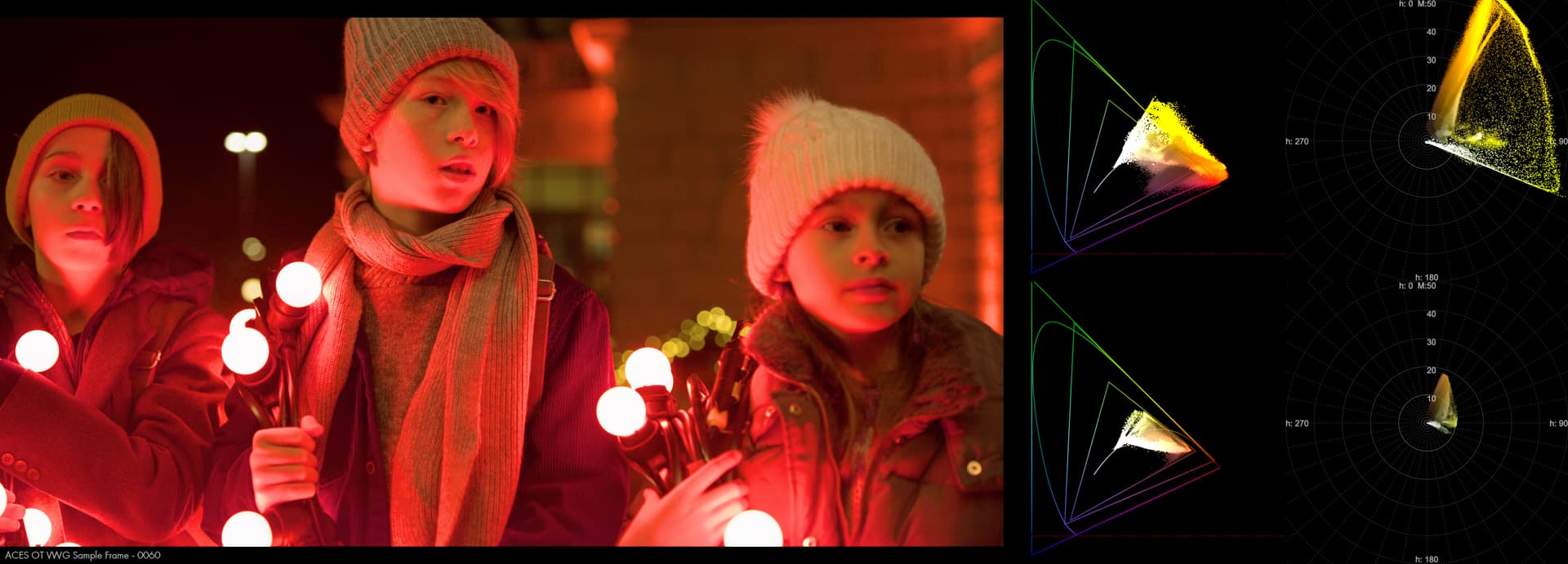
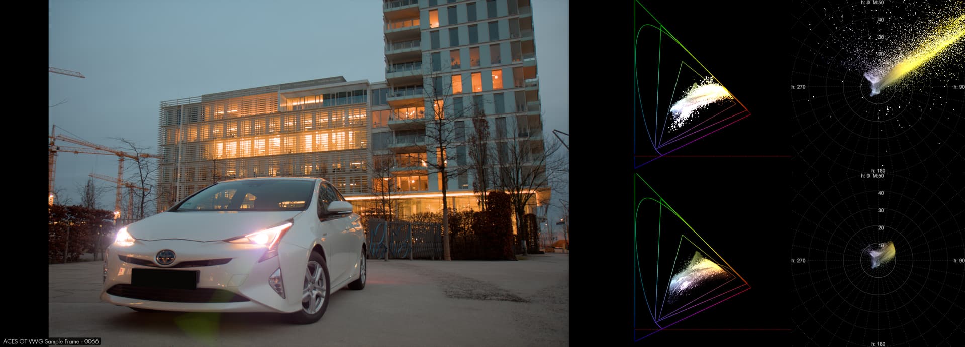
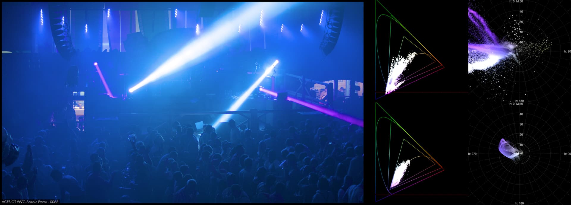
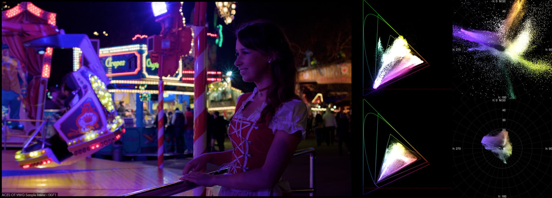
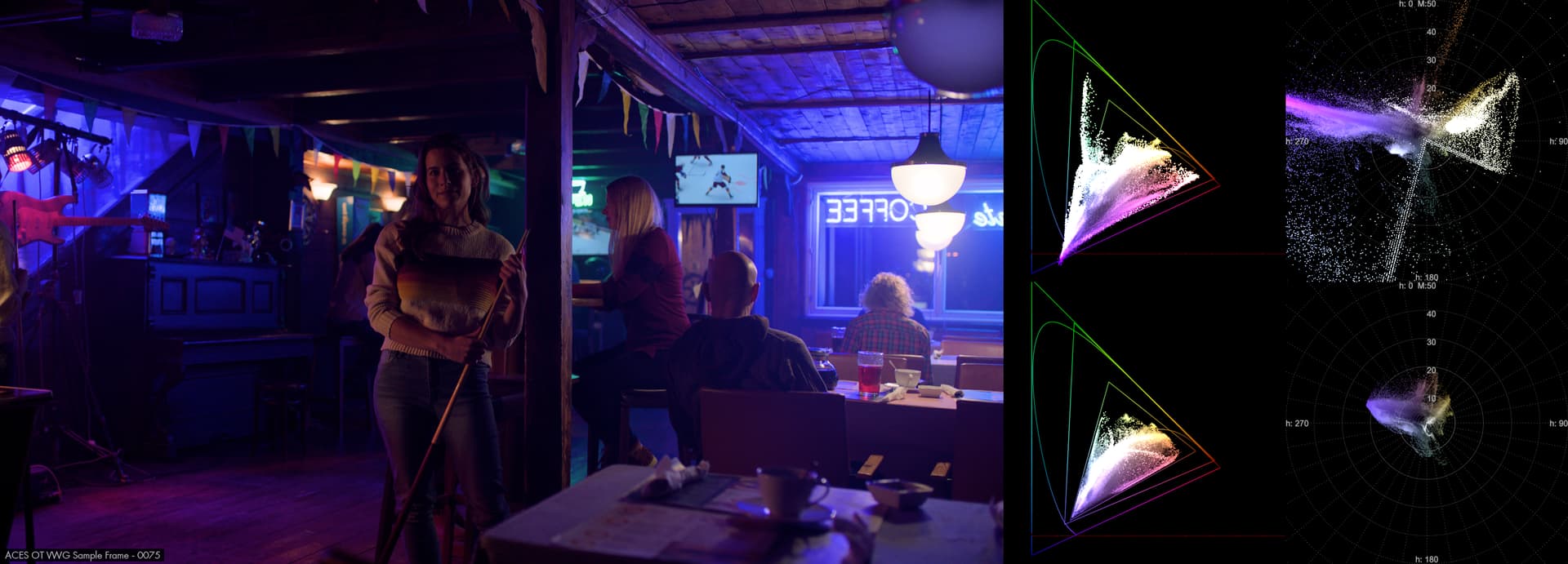
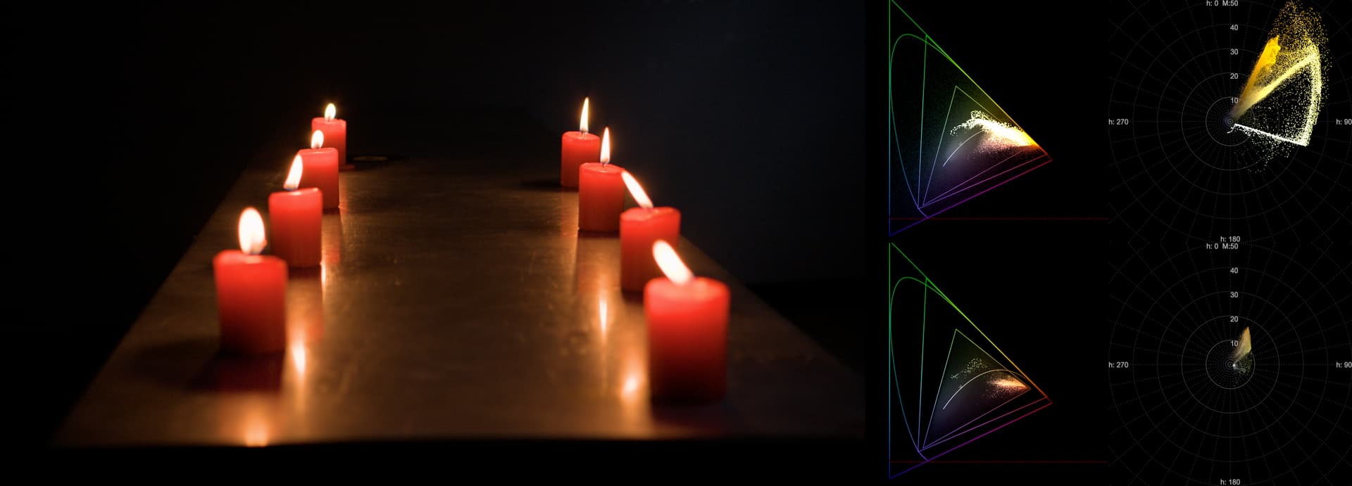
I’m incuding some sample frames that have been output using these parameters:
Note: The v20 version has a broken gamut mapper and the rendering of certain colors (especially more saturated ones) in the images above are not representative of the normal gamut mapping.
Since last week’s meeting I got to thinking how current CAM DRT could be taken into a direction where it could retain saturation for more pure colors in the highlights, but still retain typical photographic rendering in the highlights. The reason why current DRT doesn’t achieve that is that the highlight desat functionality affects all colors equally.
So I made a version of the CAM DRT that has a new chroma compression mode that changes the compression based on the purity of the color with the goal that more pure colors would be compressed less compared to less pure colors. This will then allow the DRT to reach highly saturated colors in the highlights while still having a “path-to-white”. The implementation is very simple. It’s just a lerp between no-compression at all and the user defined amount of compression. Hue is taken into account too. It all happens in JMh. When enabled, it overrides the highlight desat.
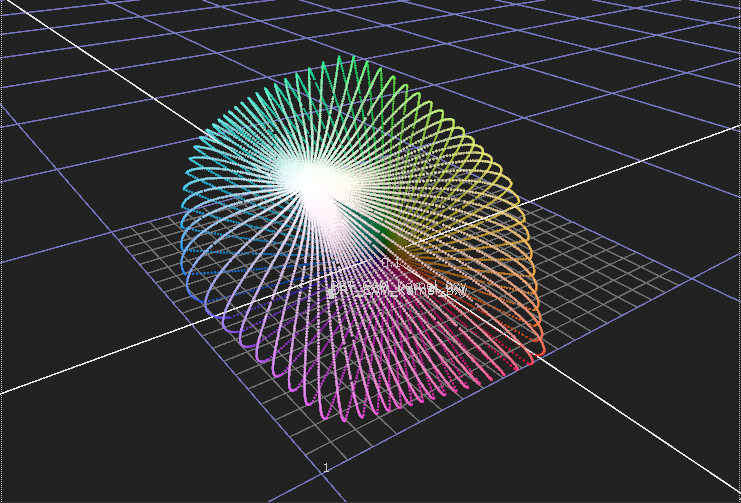
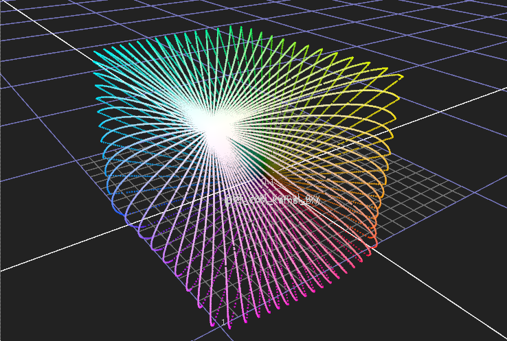
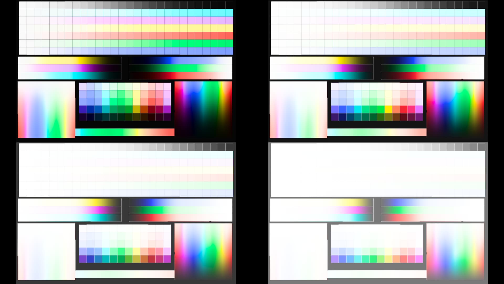
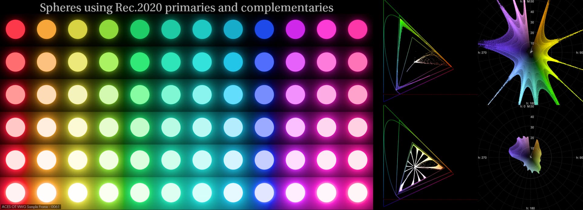
The difference is very clear when looking at the display cube:
The current version is tuned specifically for ZCAM and not for Hellwing. Reason is that Hellwig is causing me a lot of trouble and most images have white pixels (NaNs most likely) in them. While the compression works with Hellwig too, none of the internal values have been tuned for it.
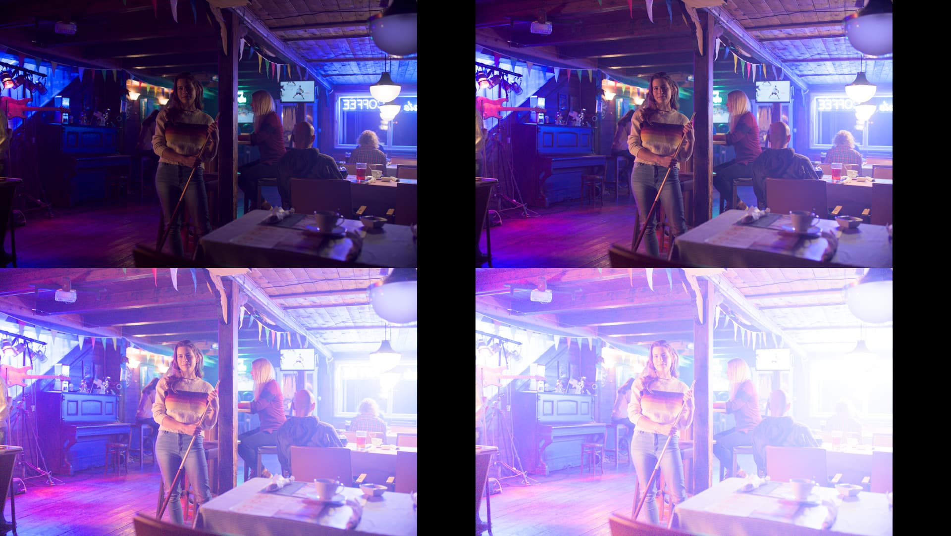
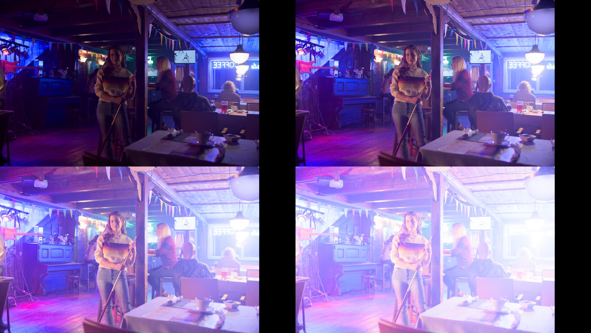
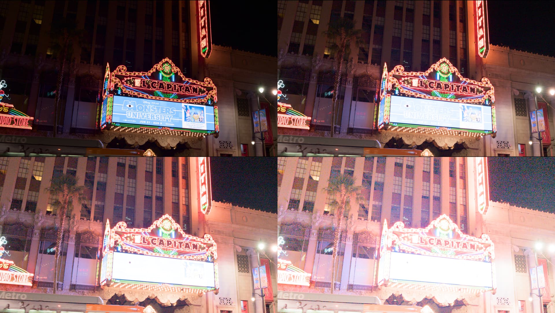
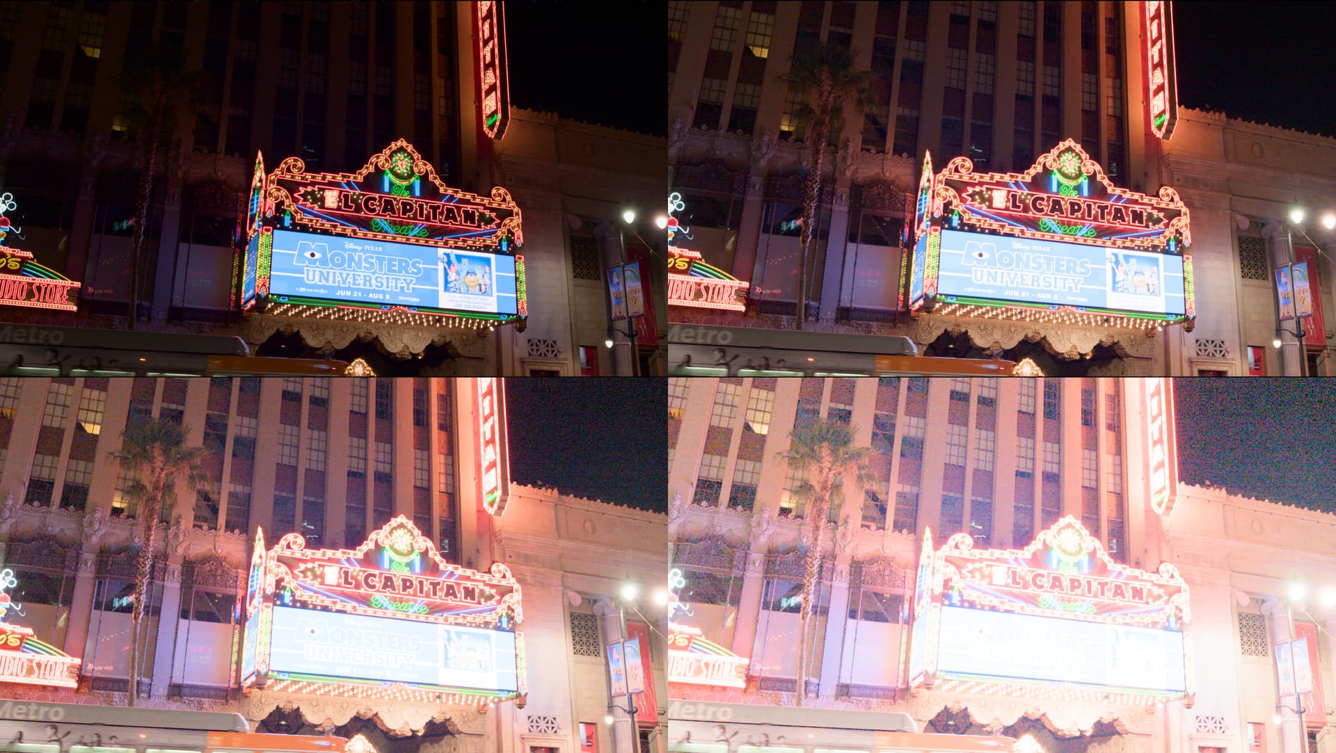
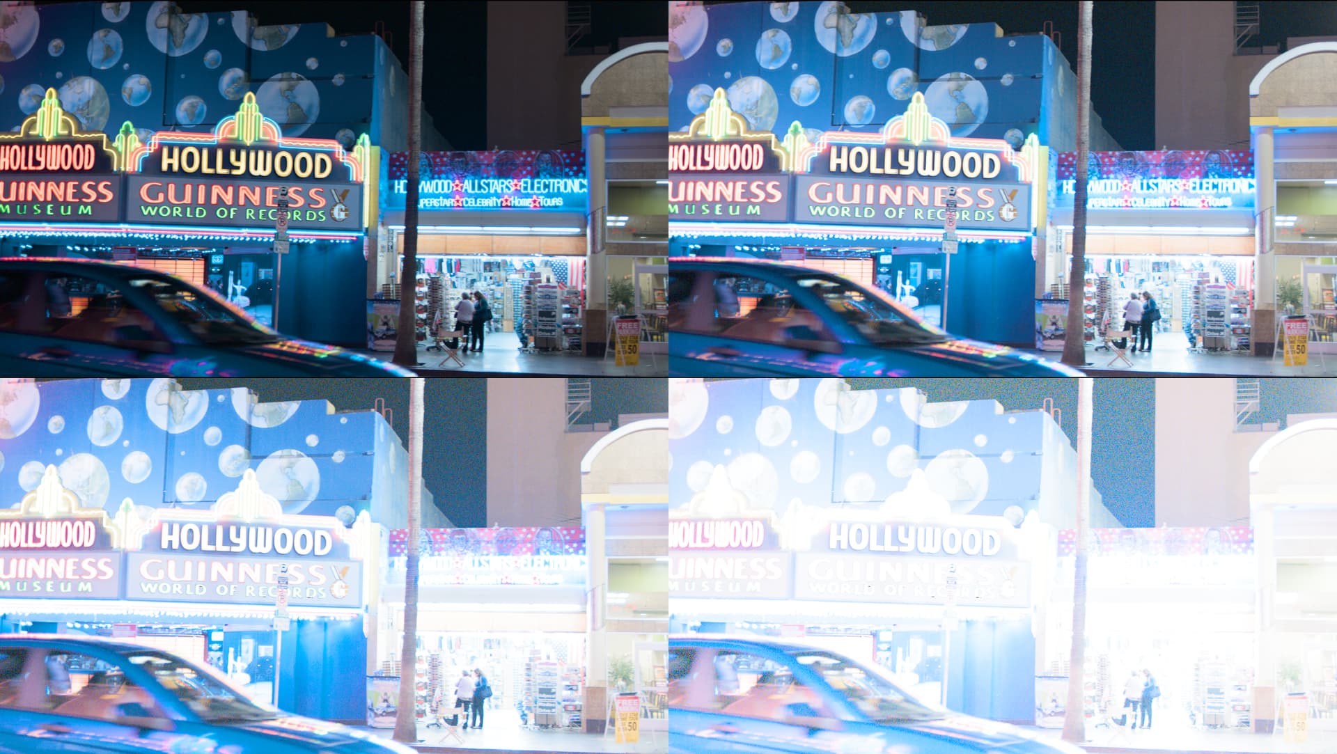
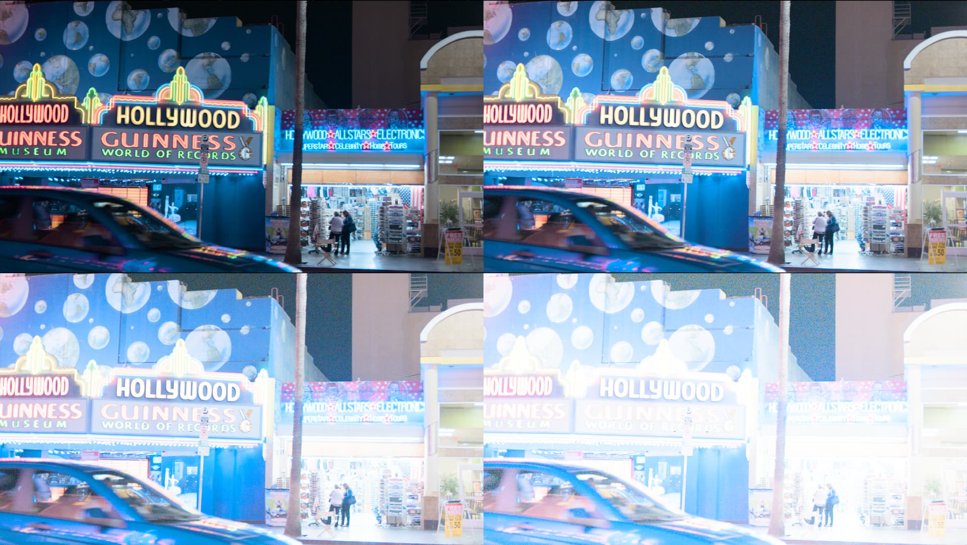
Following images compare ZCAM Candidate C and CAM DRT v20 with ZCAM (and fixed gamut mapper) and this compression mode. Each frame includes 4 exposures, 0, +2, +4, +6. First frame is Candidate C, second CAM DRT v20+compression.
The difference is noticeable. Purer yellows, cyans and magentas can easily be retained even longer if wanted. Unfortunately, the gamut mapper prevents from getting any more saturated blue or red, even if there is no compression done at all to those colors. Something to look at there…
Thinking about the compression model discussed Wednesday (10/19) with green and saturation and the acute changes of the lum/sat/hue curve a thought emerged. Is it really necessary to be able to go all the way to the corner of the color space cube or to utilize every color the primaries produce?
As the eye is more sensitive to green light might not then a less saturated green be more in balance, as perceived, with other colors? (for example the rec2020 green on a straight line vs the yellowish P3 or rec.709 greens which then might be considered to be “balance wise” over saturated.) Each hue would have it’s own “perceived balance” saturation maybe even at various intensities. A plot of a certain “perceived balance” condition may appear as a smoother curve within the CIE triangle and a smoother lum/hue/sat curve. It should be added that perhaps certain colors may extend further than others and not all will be just perceptually equal, but the point would be to have conditions which would provide for smooth curves with the models (this seems apparent with the current conditions that some colors may need to be set aside.)
This might mean that not all possible colors of the primaries may be utilized. But it might also provide for a smoother and more perceptually pleasing gradient of the “usable” colors. (If certain saturation, beyond the “usable” are desired then maybe move to a larger color space.)
There may still be the possibility to utilize the “unused” colors if desired, but with a caveat that these may cause acute changes of the curve or need some additional compression/smoothing scenario. (If those colors are desired then maybe that will require more computation time.)
Even with the addition of more primaries, all of those possible colors would likely not be fully utilized with the base models (even though this could provide more “usable” colors.)
This acceptance of not utilizing all the colors possible by the primaries in order to achieve a set of more controllable colors can be like accepting that a camera records more colors than can be utilized. This is likely an acceptance that will remain with photography.
From a photographic perspective that makes a lot of sense.
But I think a lot of the motivation to be able to hit all the corners of a display gamut comes from graphics. If the people paying the bills have a logo that uses 100% sRGB red in display referred scenarios, for example, then they expect to be able to achieve that, and no argument about “a smoother and more perceptually pleasing gradient” is going to change their minds!
There is some new stuff un the repo.
v22 has some bug fixes, but I’m still trying to track down a weird M collapse I’m seeing with very high J values. (I’ll try and talk through this in the meeting tomorrow)
And a first attempt at implementing the Evolution of the Daniele curve. danieleEvoCompressionCurve.blink
Currently it’s either failing to compile (with pow), or throwing all NaNs (with spow).
Looks like that error was my definitely introduced by me when translating into the Matlab I sent to Alex. @nick 's blink implementation looks right to me.
The resulting differences when i fixed my calculated value of u_2 was very small, but enough that it made me want to tweak the parameters that I had previously shared to the following:
n_r = 100.;
g = 1.15;
c = 0.18;
c_d = 10.013;
w_g = 0.14;
t_1 = 0.04;
t_1 could be kept =0.041 but 0.04 feels much cleaner. Stupid reasoning but since the values are essentially made up anyway, I think a round 0.04 is more defensible and doesn’t differ all that much…)
Of course then that reasoning doesn’t apply for c_d. The value of c_d gets us extremely close to 10.0 for a value of 0.18 (9.9999) - maybe not important to hit 10 so exactly. But to me 9.9999 feels better than the 9.9871 we’d get if c_d=10.0.
Either way can be reasoned and the differences are so small they’d be negligible - it just depends how we end up documenting the origin of the “magic numbers”.
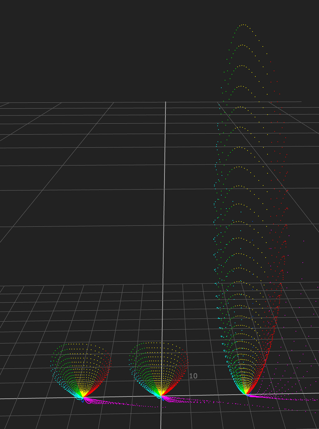
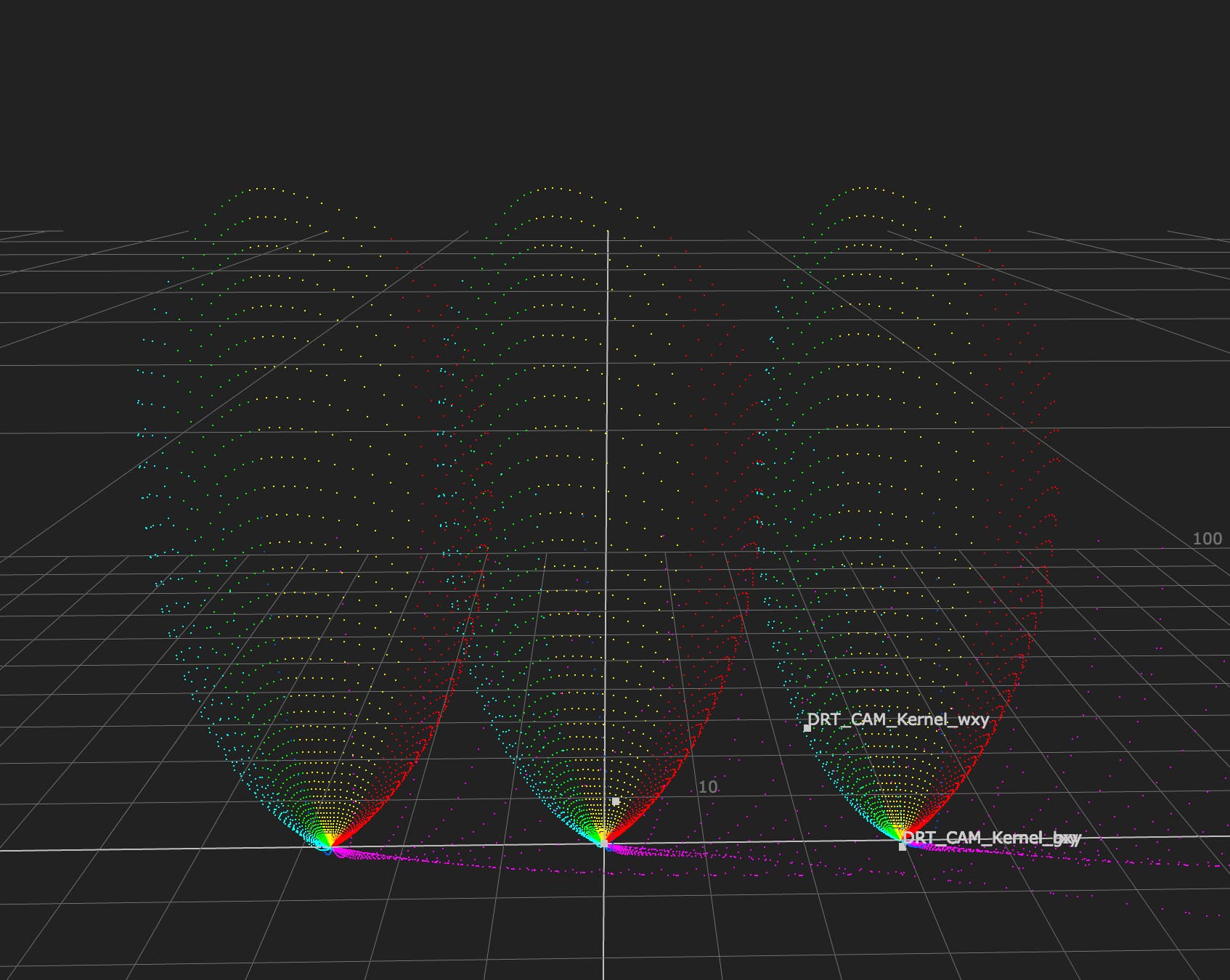
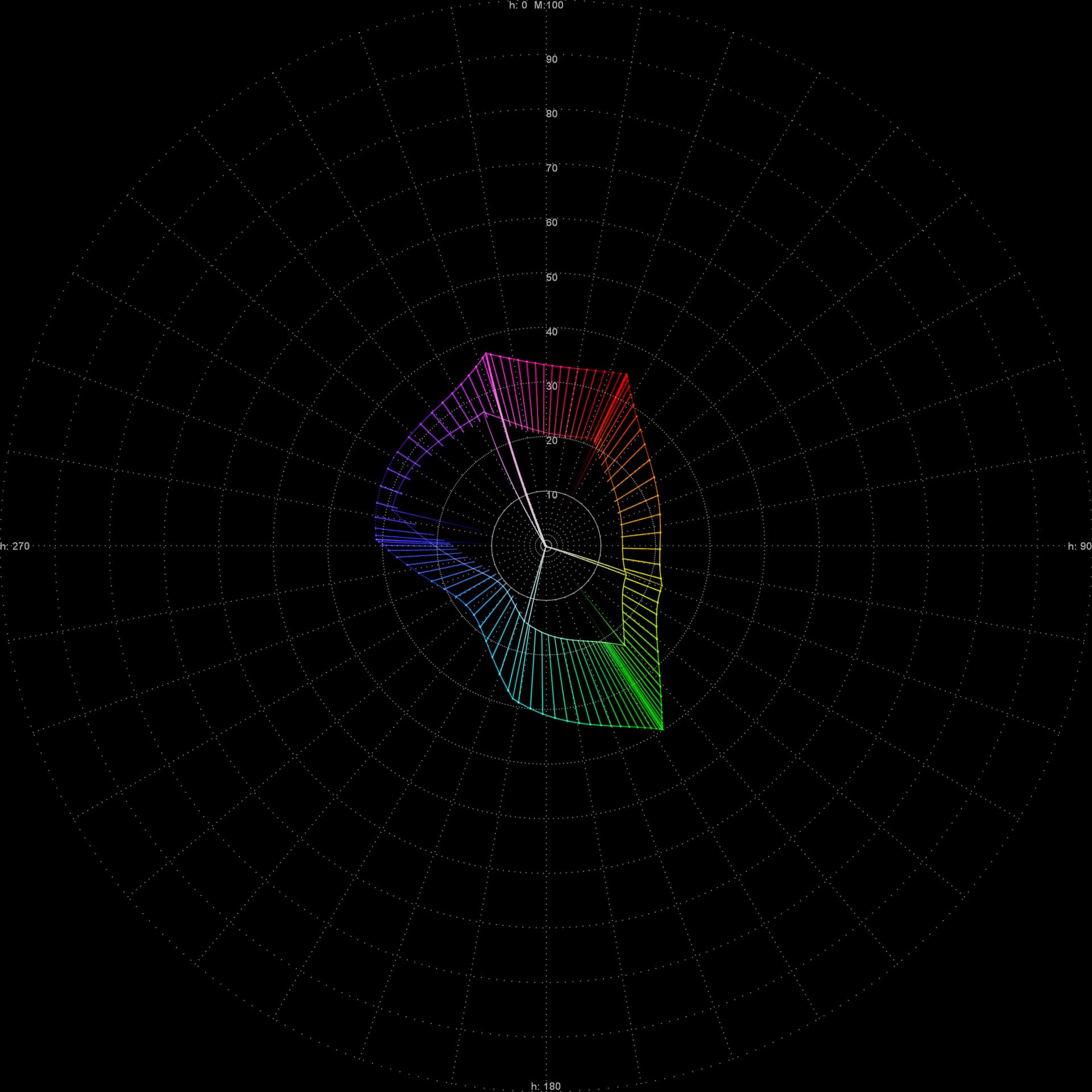
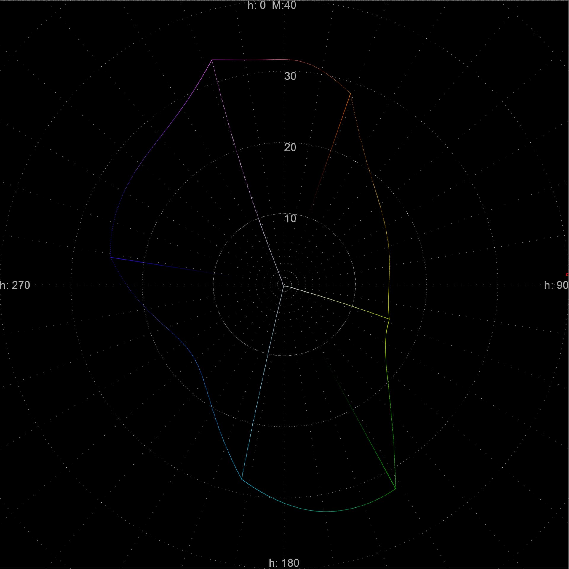
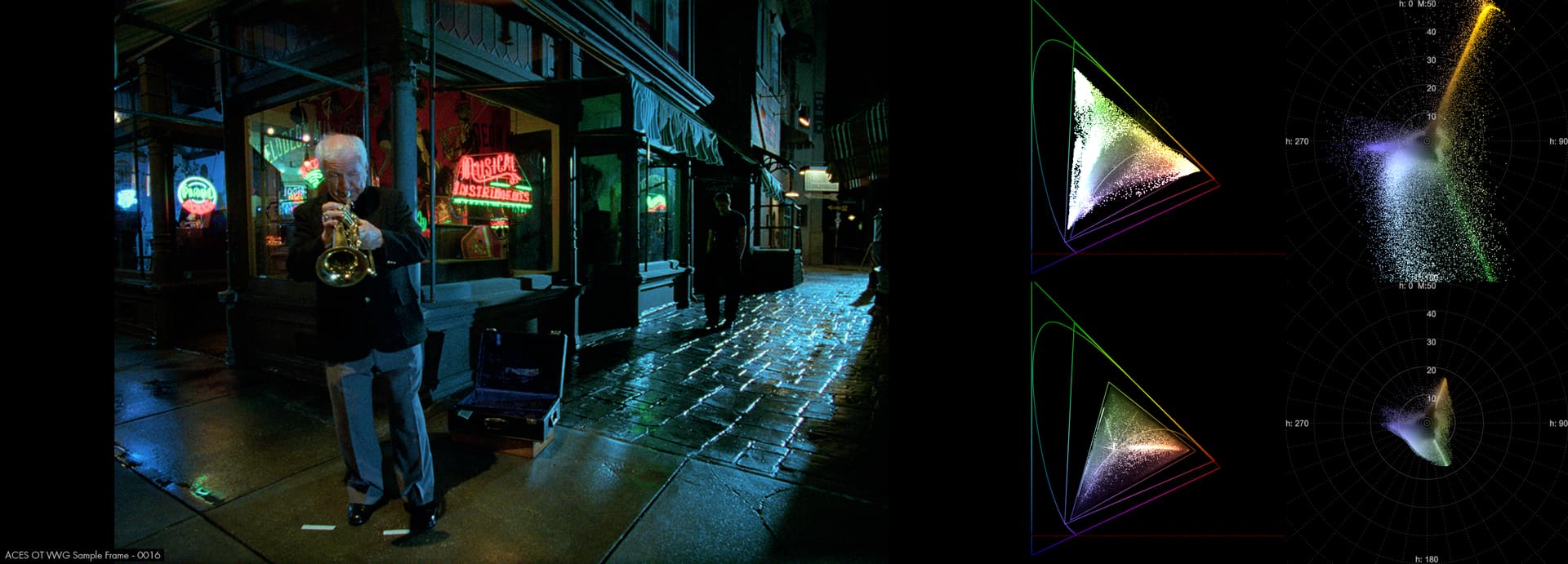
Starting to work up some tooling to create plots in JMh space.
J: is collapsed
M: is 0>100 from the center
h: is radial with 0 at the top
Outer hull is AP1, inner is 709.
Connections lines show the path AP1 values take towards the 709 boundry, as seen in JMh space.
In theory a straight projection towards the center of the image would represent perceptual hue preservation, while off angles represent a ‘hue skew’.
Might be useful to people?
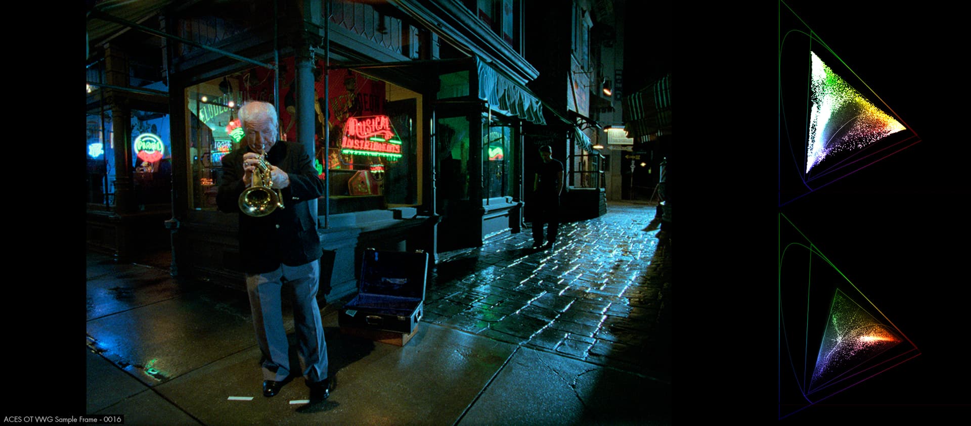
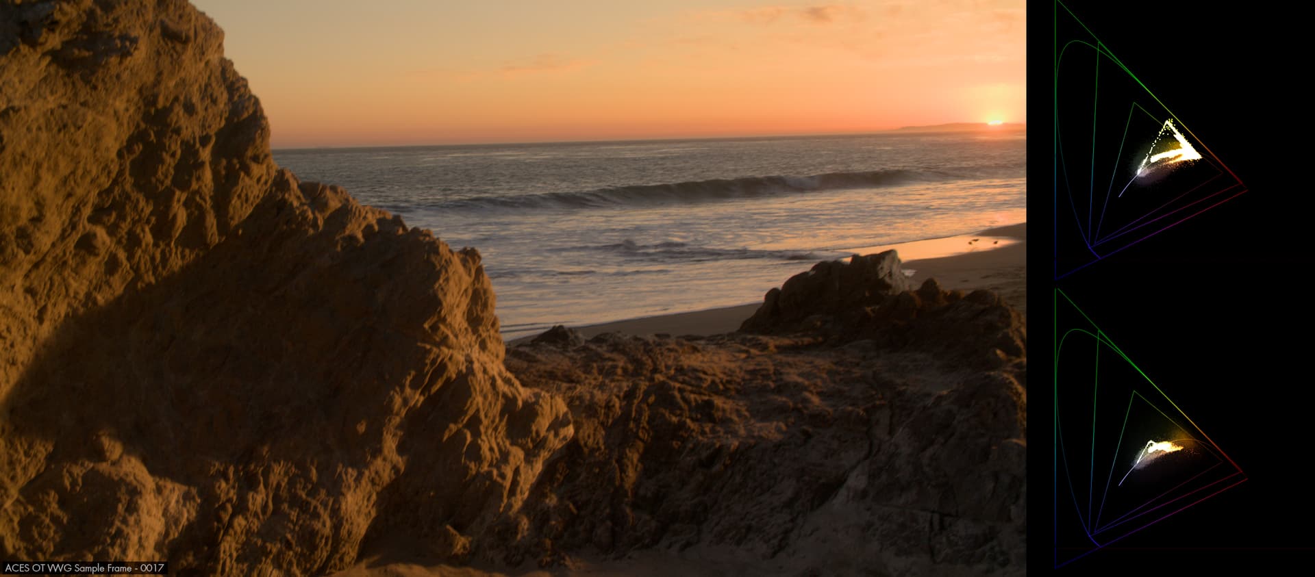
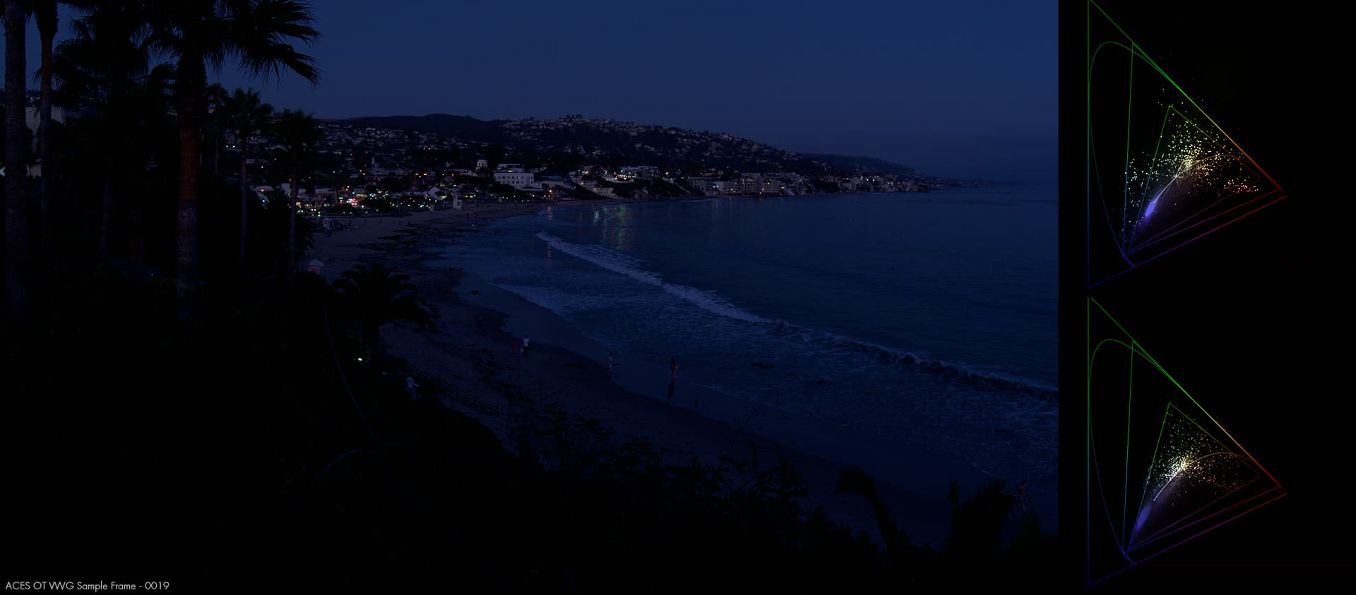
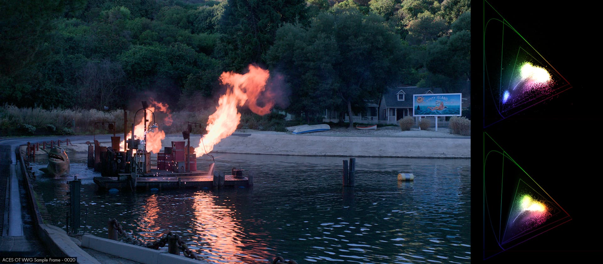
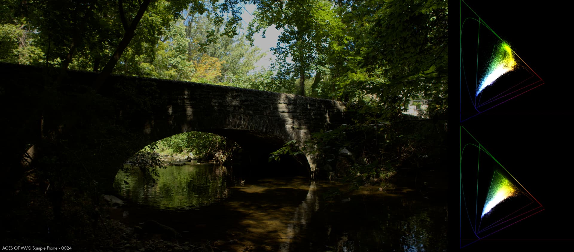
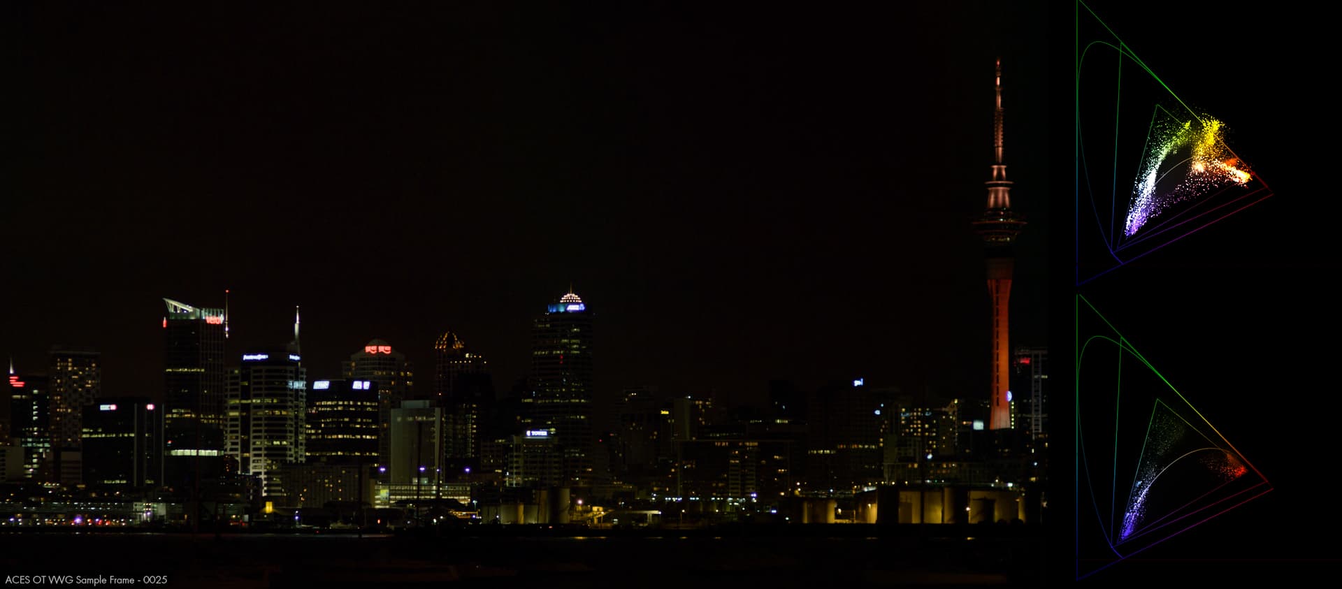
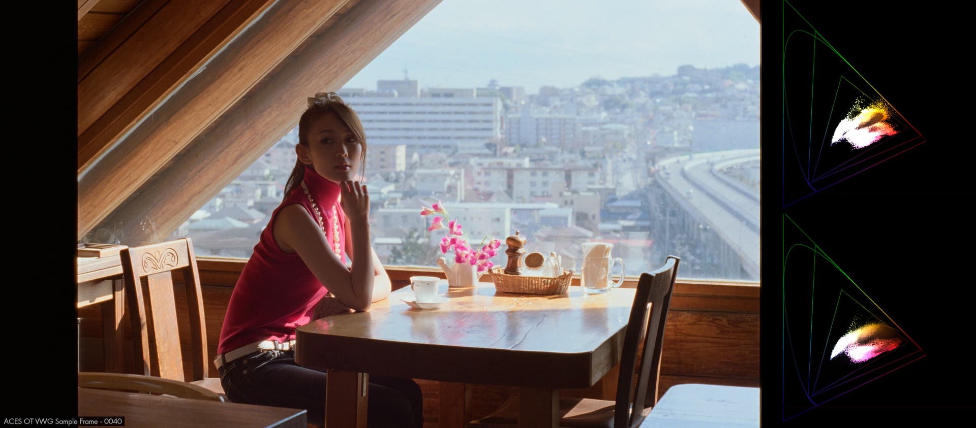
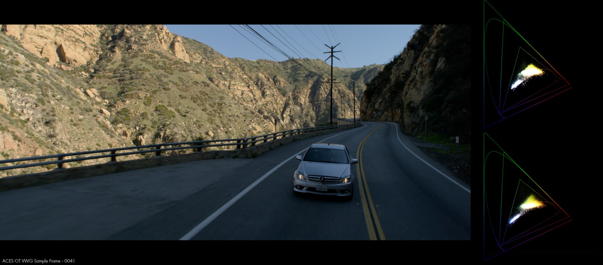
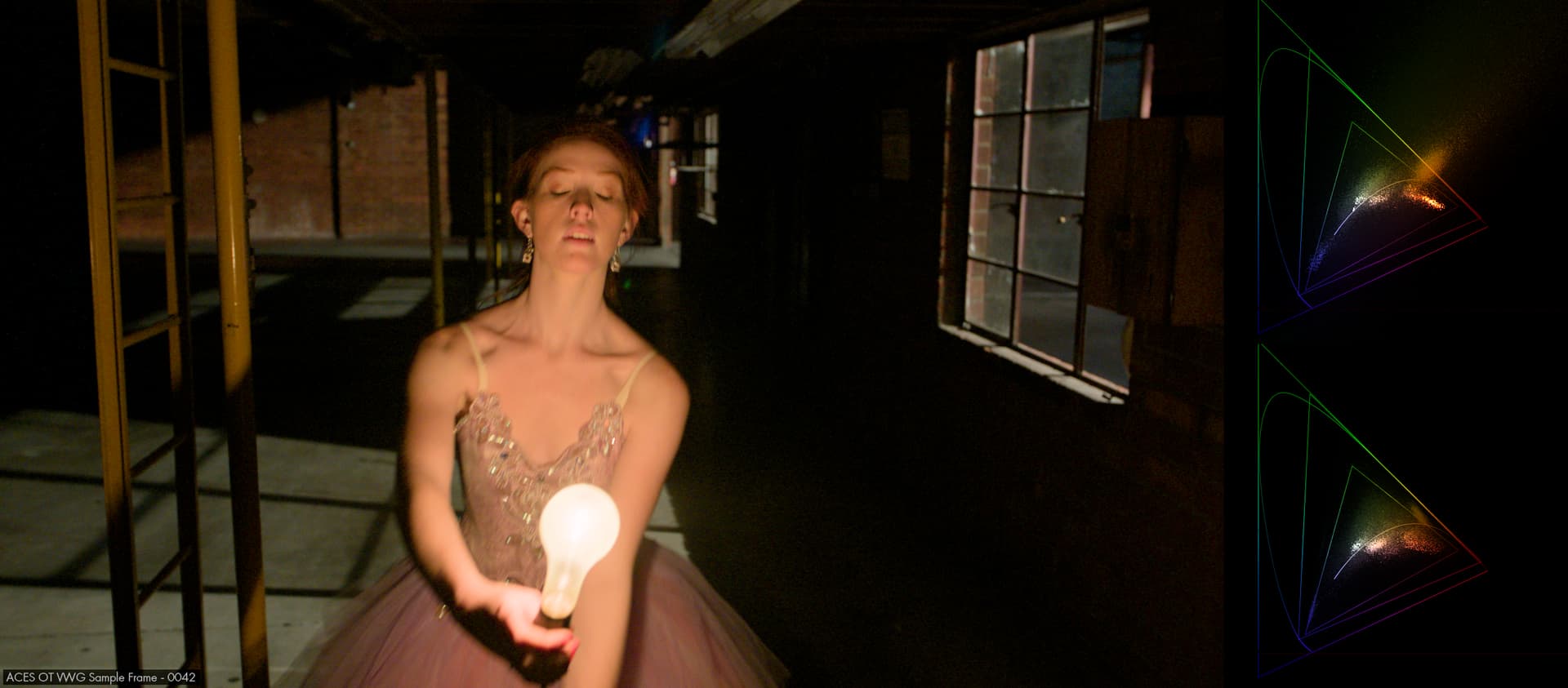
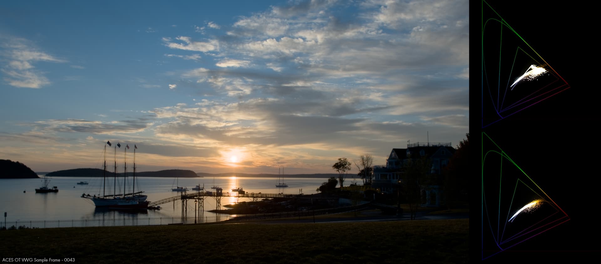
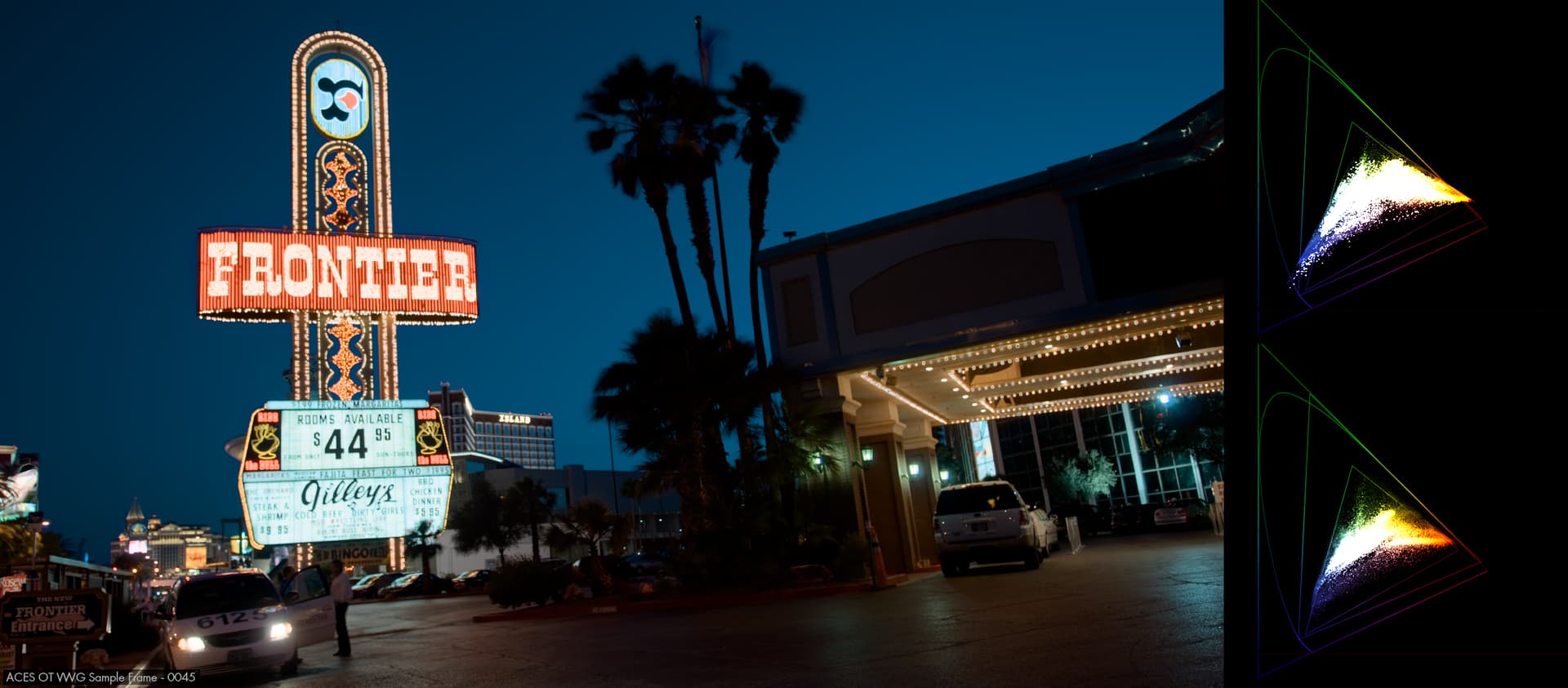
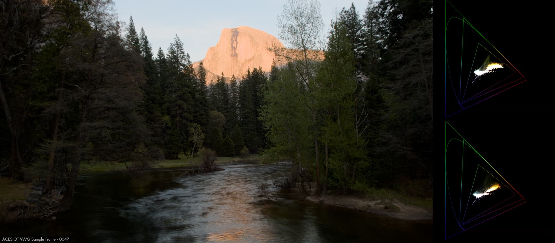
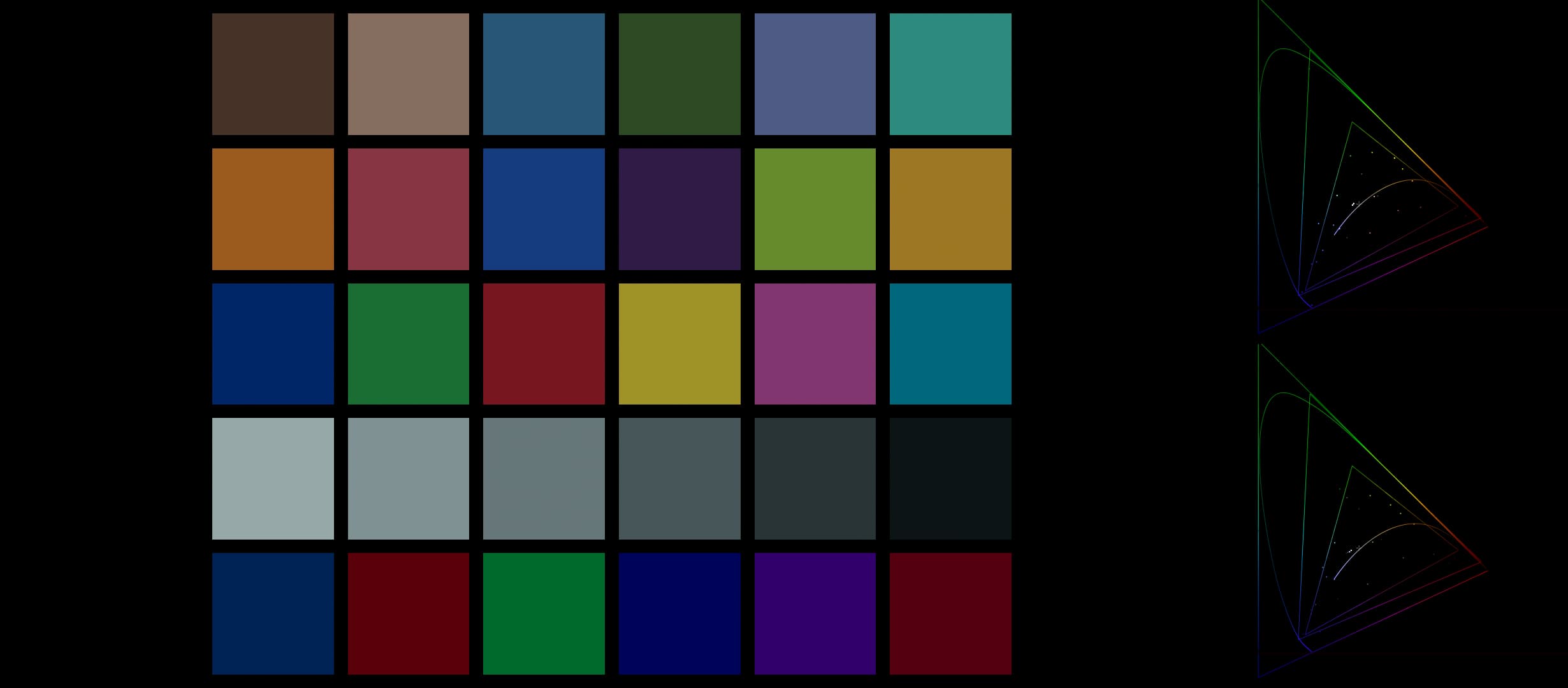
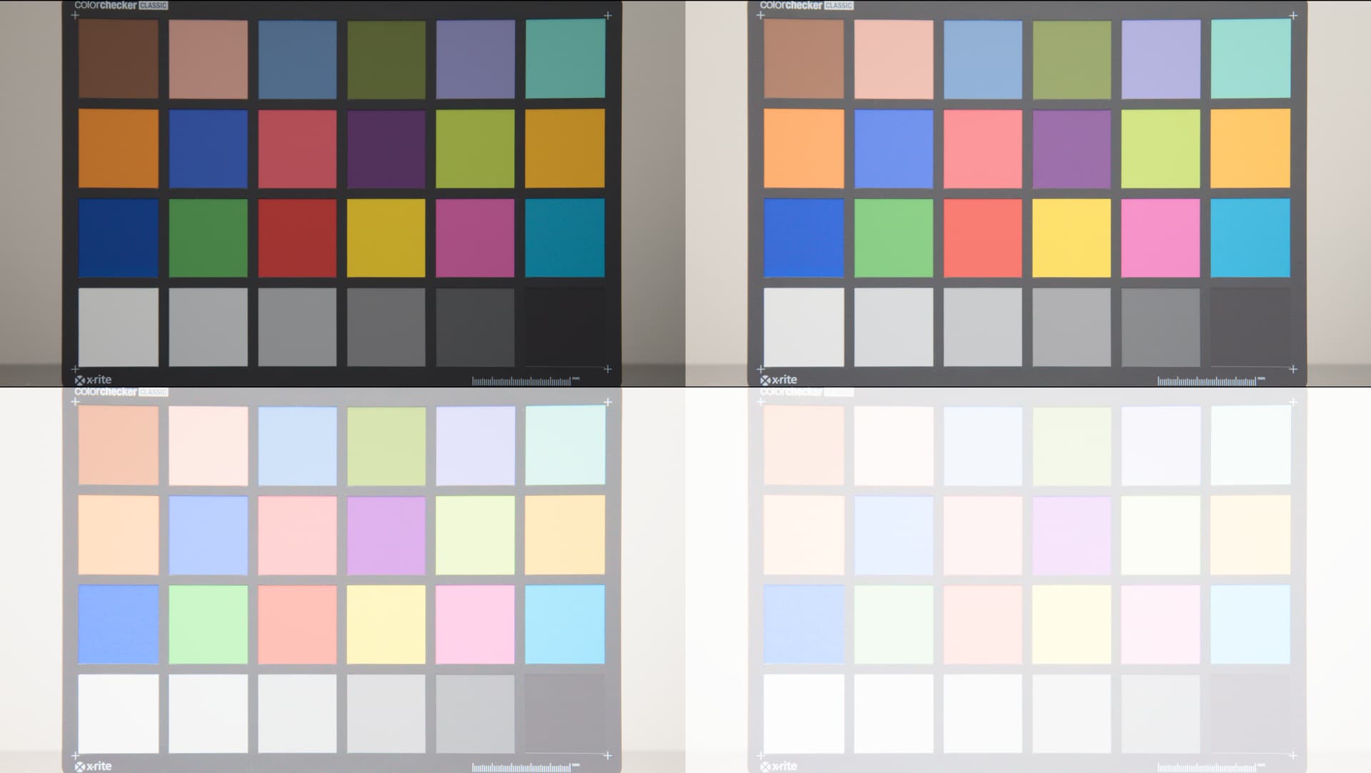
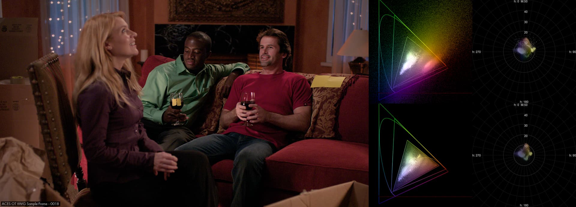
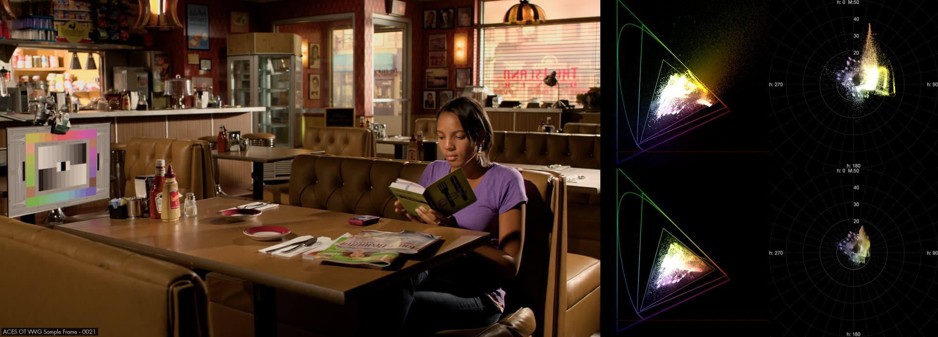
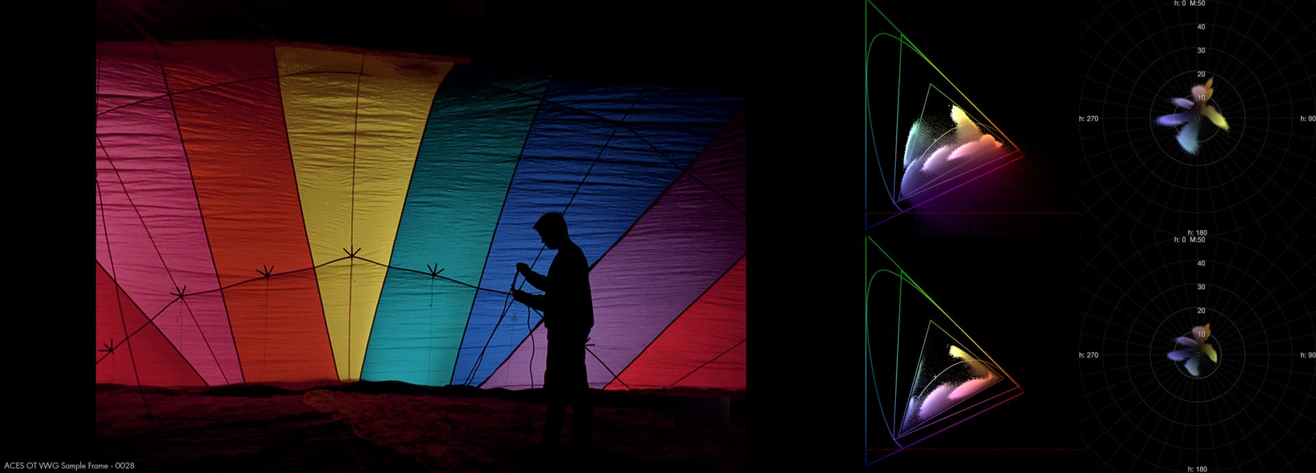
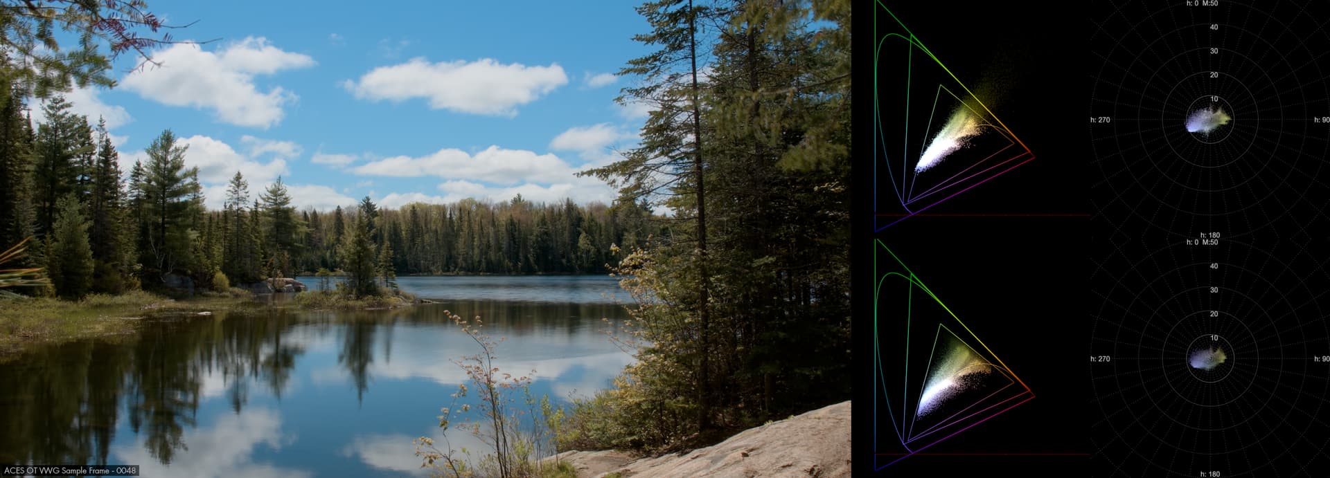
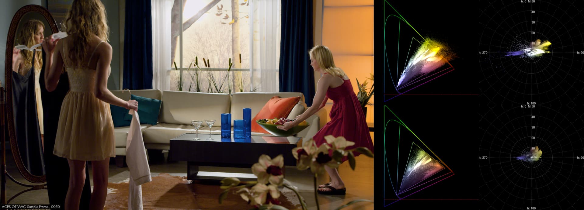
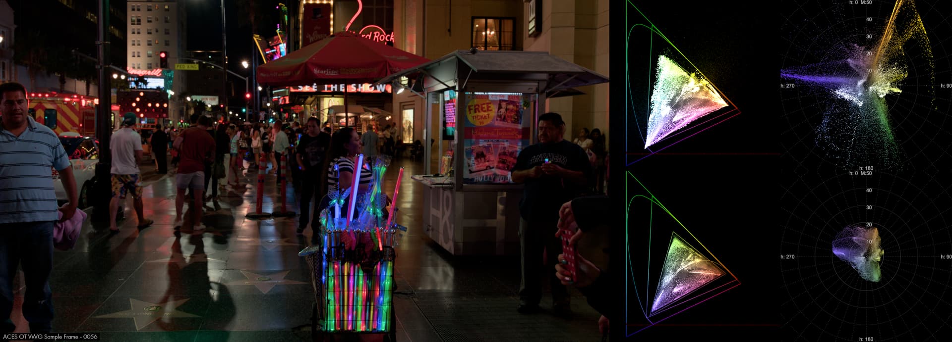
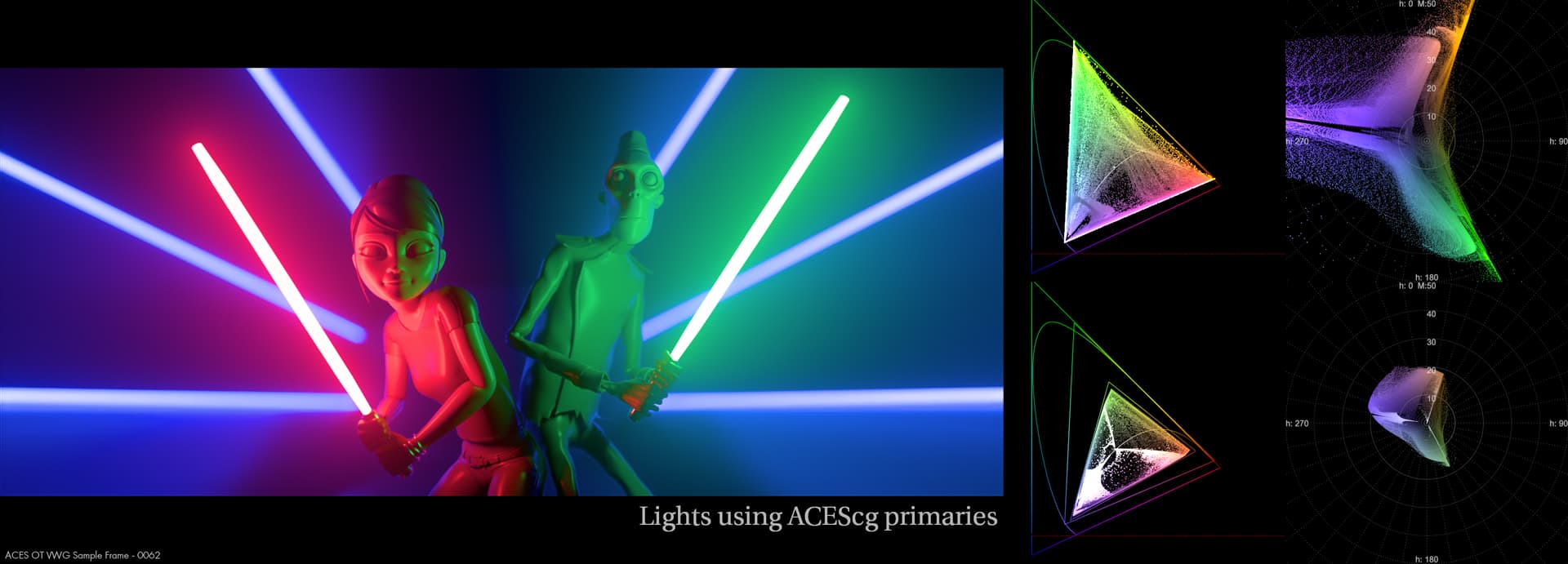
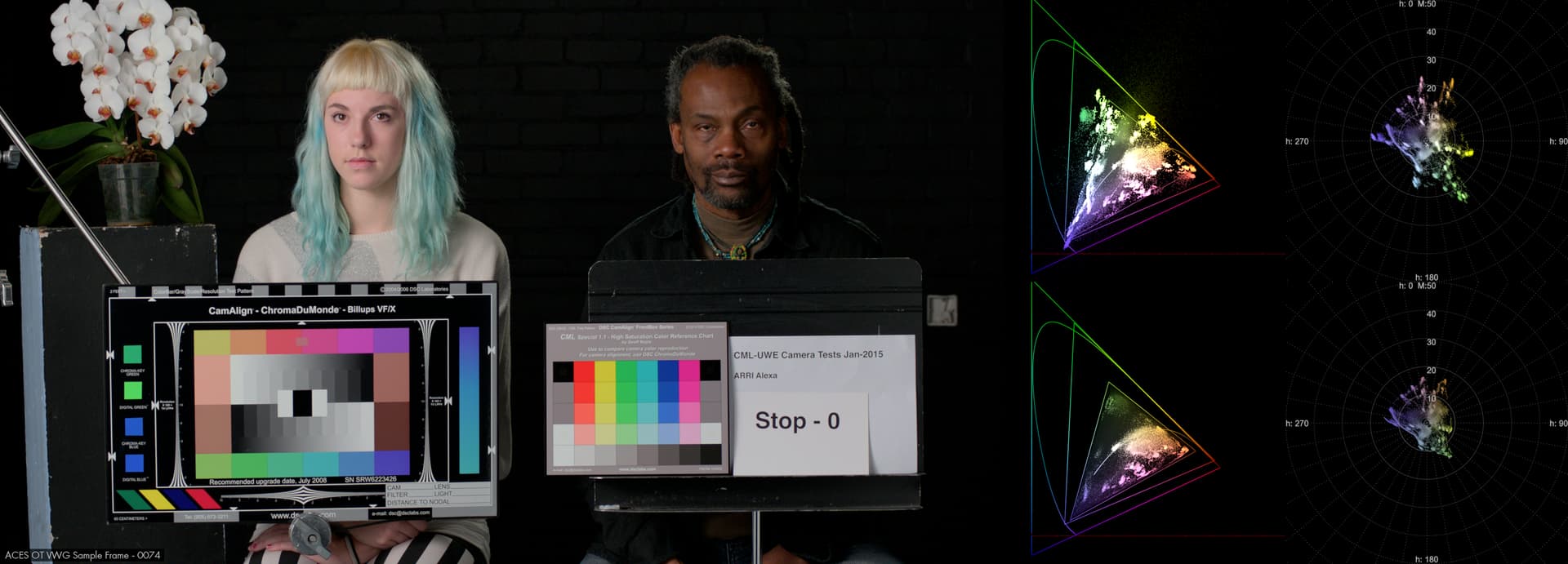
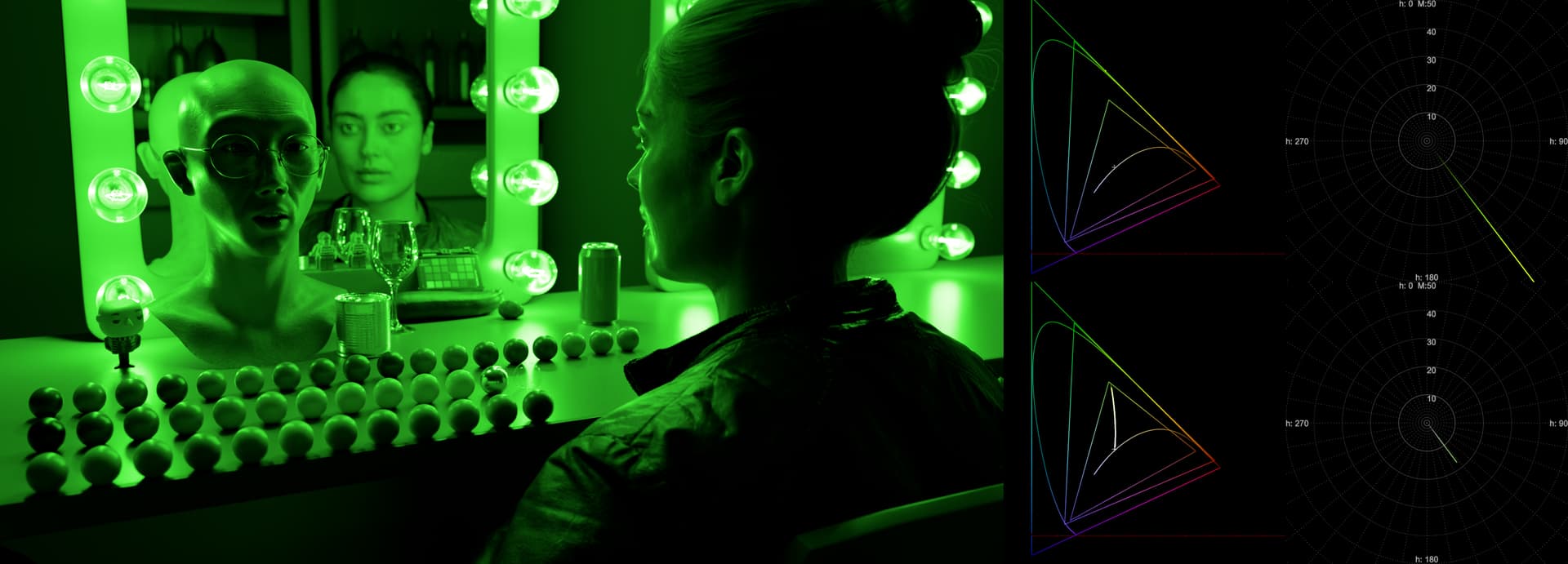
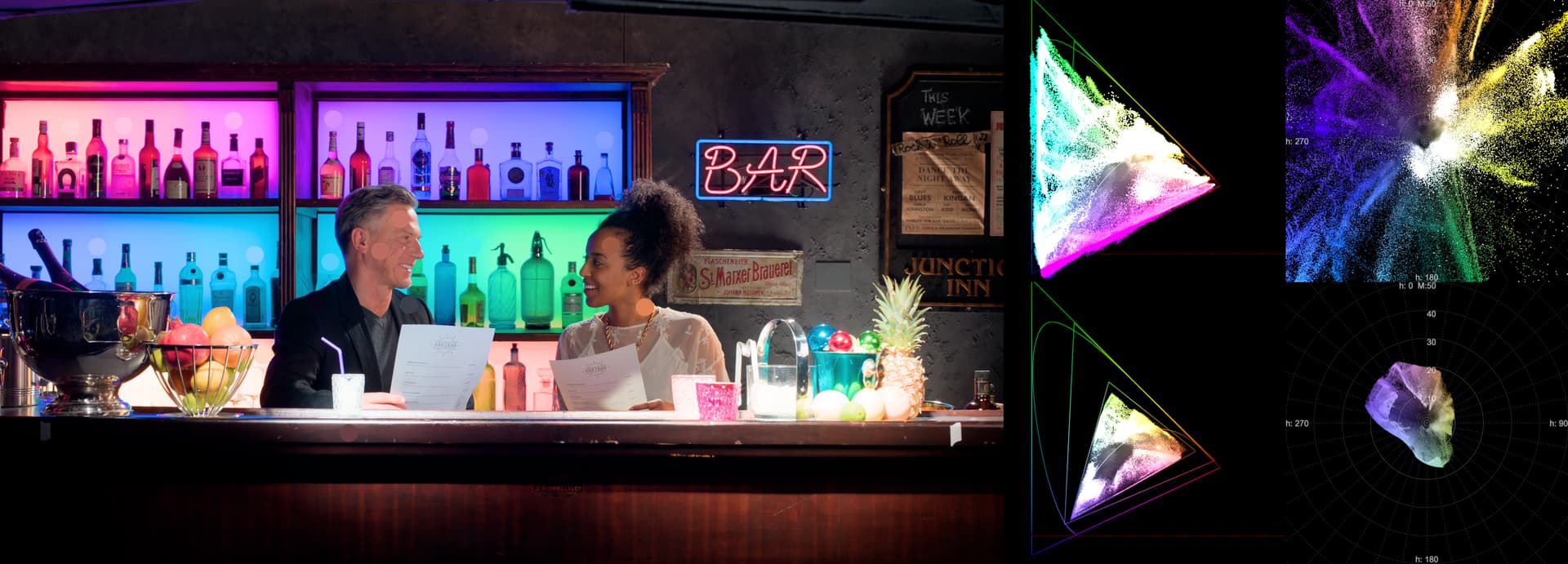
I’ve rendered out a bunch of images through the CAM_DRT v023, with Yxy and Mh, before (top) and after (bottom).
On thing that’s interesting to me is how some images with lots of out of gamut values, due to near black noise, don’t nesseasaryly produce large M values. Whilst some other well constrained images produce large M values, due to their high brightness. (expected, but interesting to see actually see it visually)
The compression looks to work impressively and these SD rec.709 samples really look nicer than that from the original candidates. I would like to experience these in HDR P-3.
I have been having some difficulty getting things working in Nuke (Non-commercial) as I have little experience with that. I am, however, fluent in DaVinci Resolve and am looking forward to when this all will be available for such. When might this be put into a DCTL? (and I hope the programing fits as I understand transfer between Blink and DCLT can sometimes be one way.)
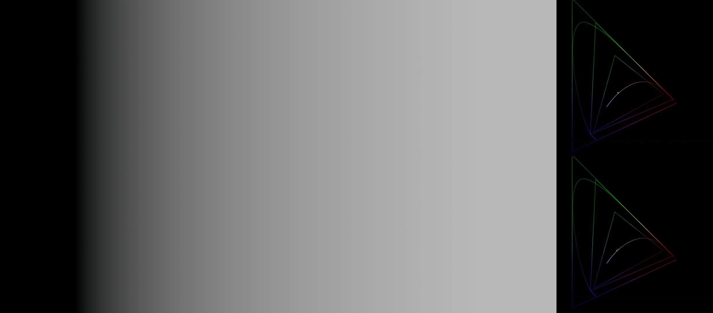
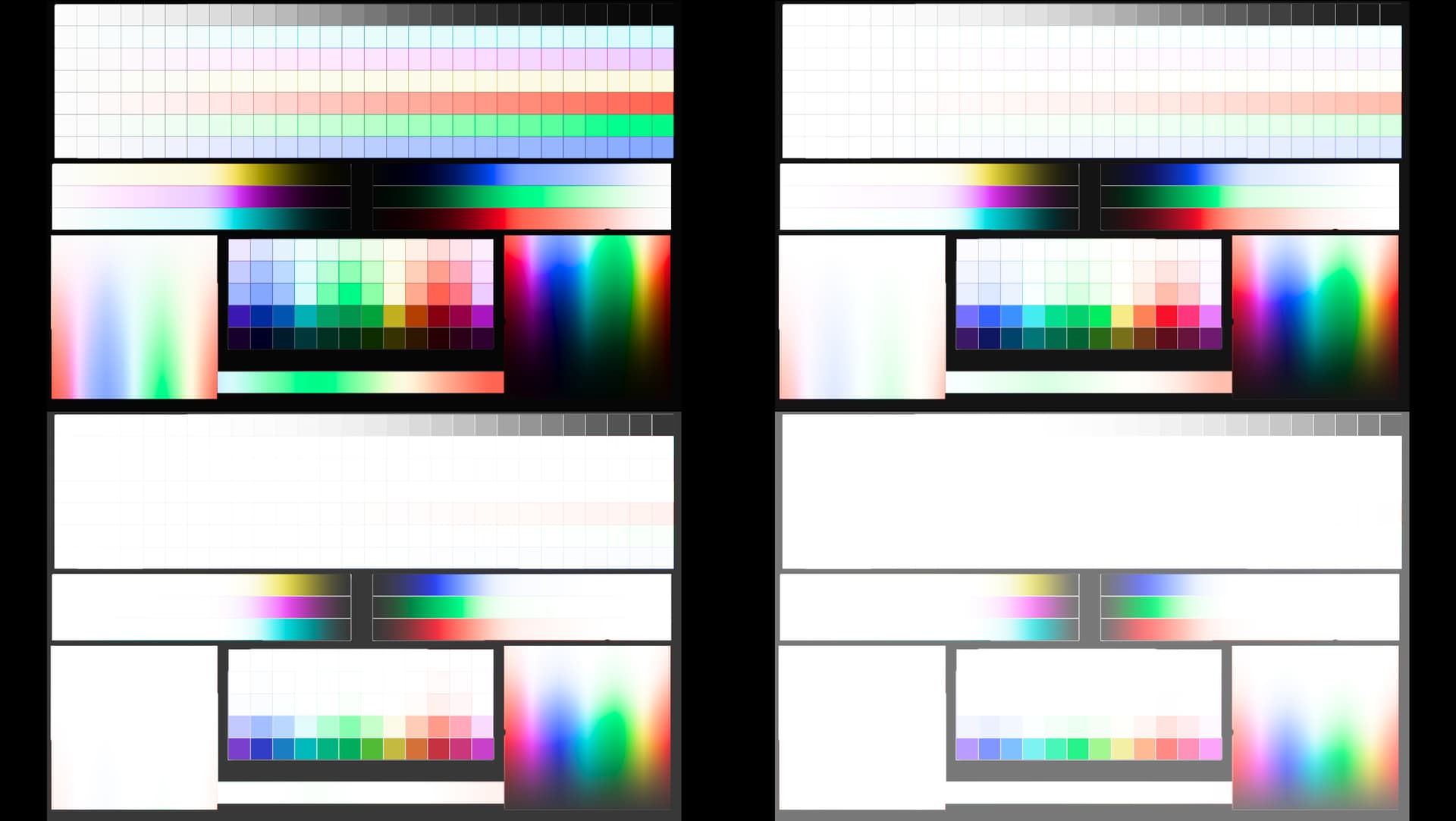
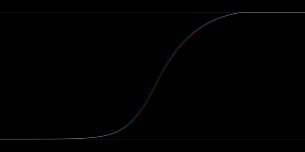
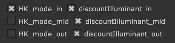
Following ramps show one of the main issues that CAM DRT (and Candidate C) has. The input is a gray ramp with whitepoint shifted from ACES whitepoint to D65. One would expect that if the DRT is neutral and doesn’t cause temperature shift the RGB ratios stay steady until the saturation roll-off kicks in.
In both cases we can see that the temperature changes. The way we’ve compensated this is with the highlight desat. The problem can be lessened by compressing more but then highlights won’t have much color left anymore. The issue is not seen in ACES 1 or Candidate A (or any other DRT I’ve looked at).
In doing the chroma compression, in effort to retain the colorfulness in the highlights longer, this problem causes the colors to shift, typically warmer. IMO, this should not be happening in a neutral DRT; this type of thing should happen in LMT. This I believe is also the reason why neutrals have that color cast I’ve mentioned a few times.
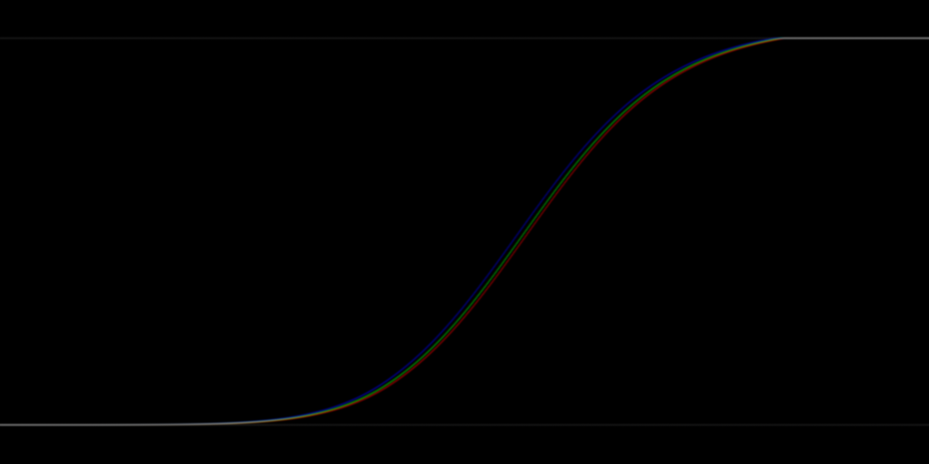
The following ramp shows what would come out if there was no highlight desat at all (Hellwig):
Hey @priikone, It’s definitely not intentional, I think I might have fixed the shift in v024.
Slightly goofy mixed up between discount_illuminant and discountIlluminant in the code.
I’ve also updated the LUT repo with this version, baked out for other apps:
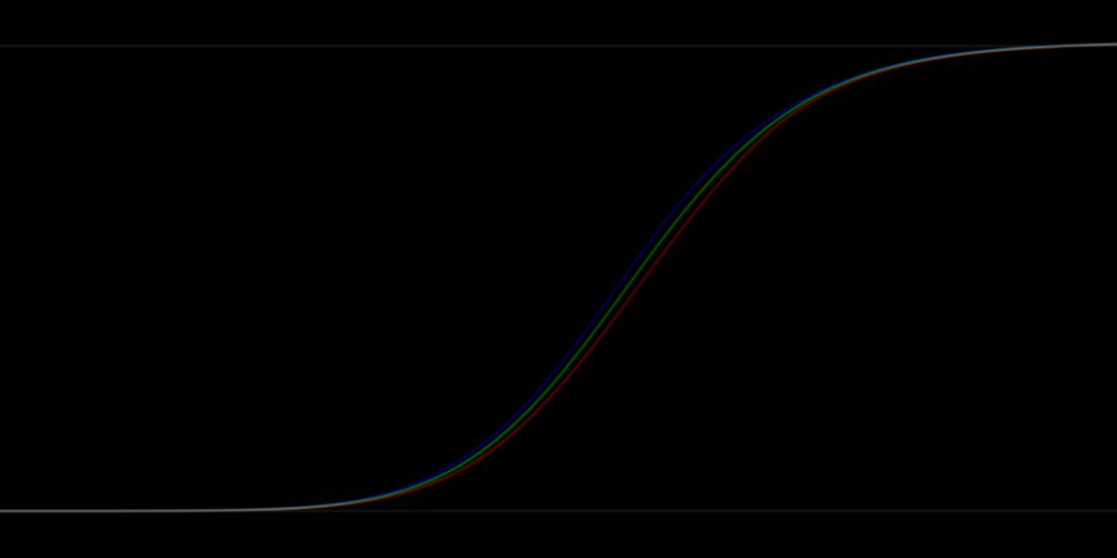
v24 fixes the pure gray ramp case with Hellwig, but unfortunately it has no effect on the examples I posted above. They still behave the same way. The discontinuity when Hellwig hits display white is still also there. Following is gray ramp with ACES whitepoint shifted to DCI whitepoint and given as input to v24 Hellwig:
So I think I’ve gotten the discontinuity under control.
It seemed to be rooted in HK mode, and also looks to be the same issue as “J collapse” issue I’ve been chasing.
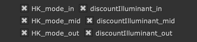
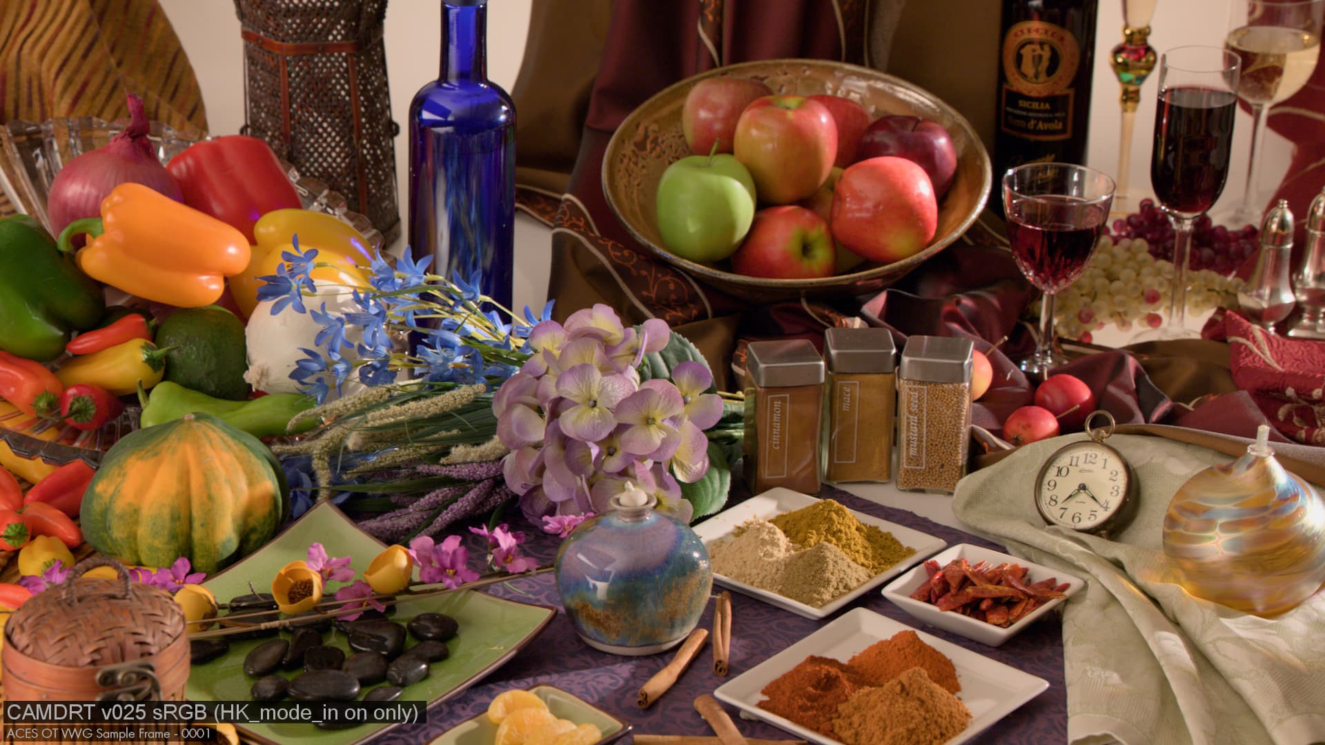
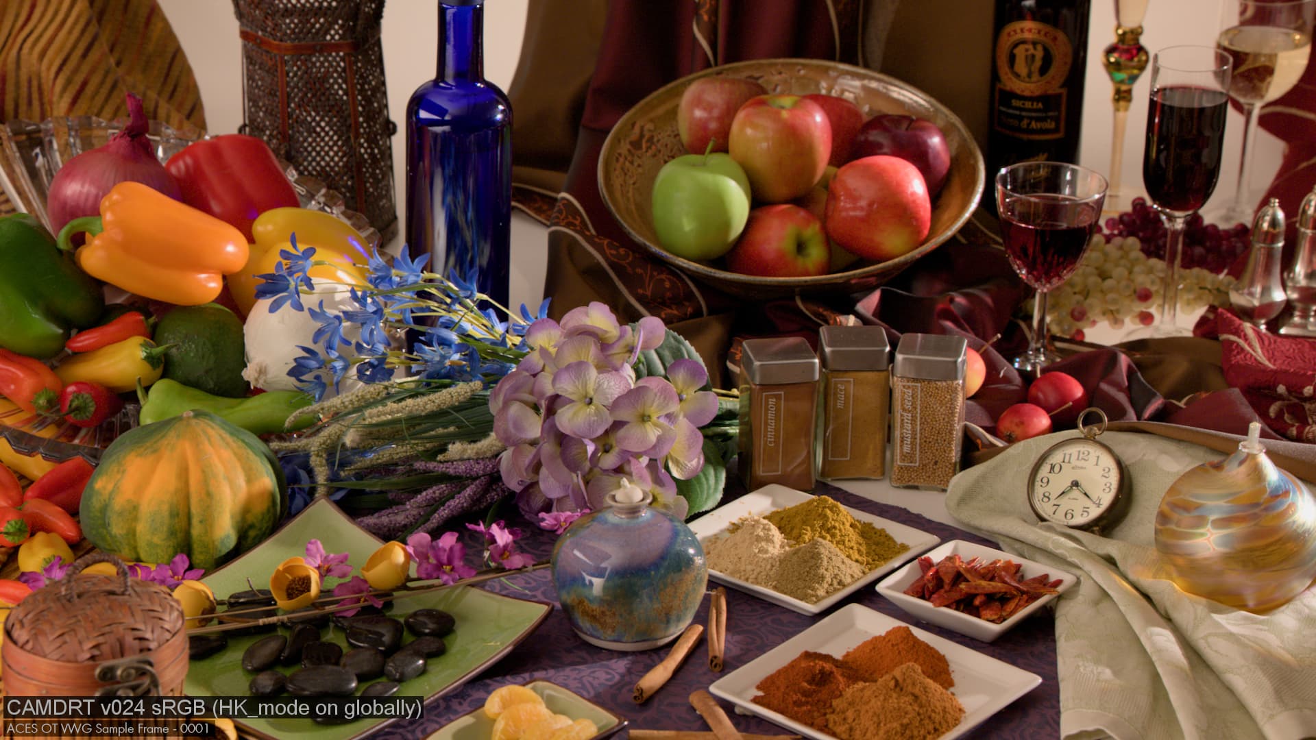
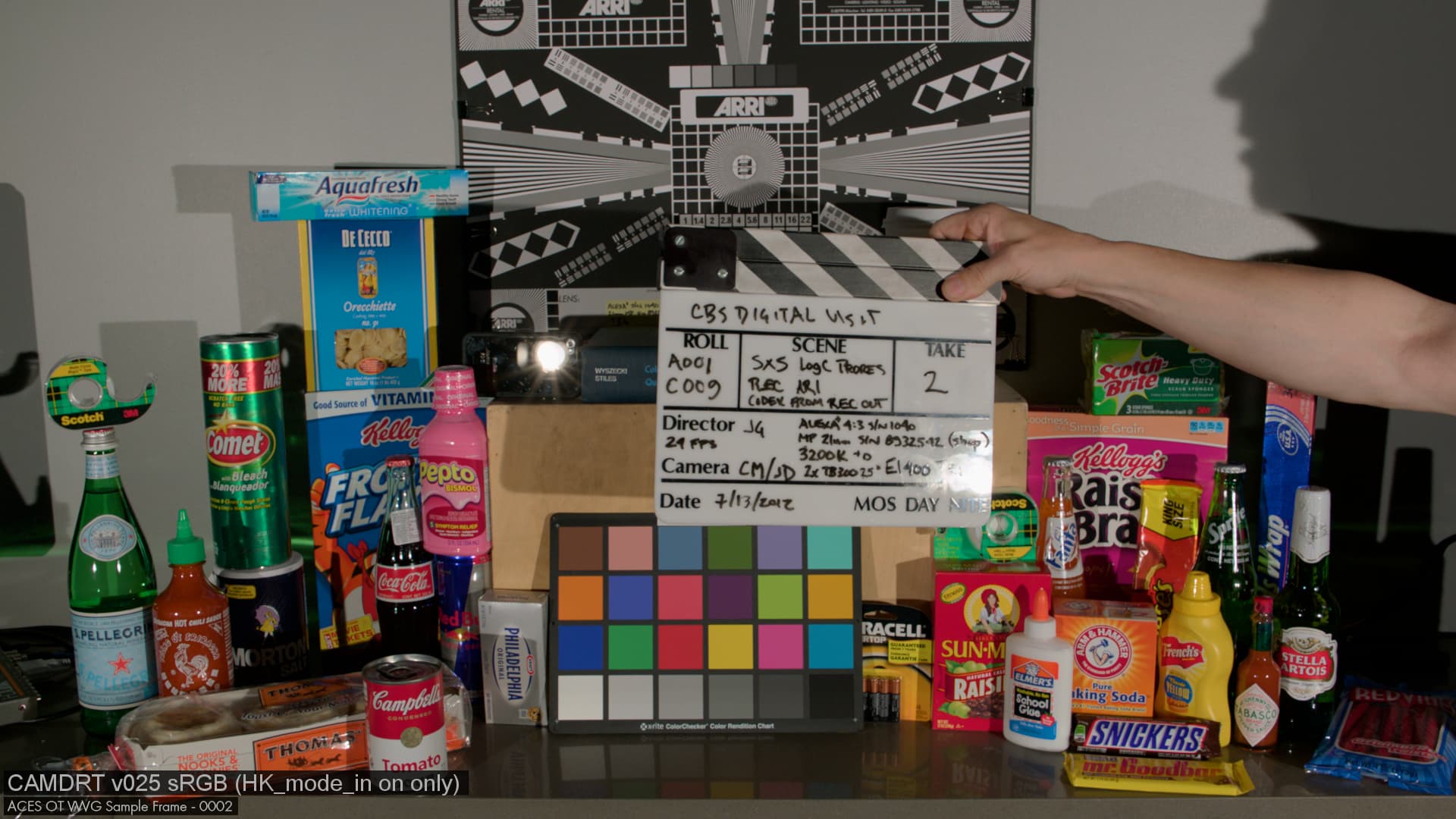
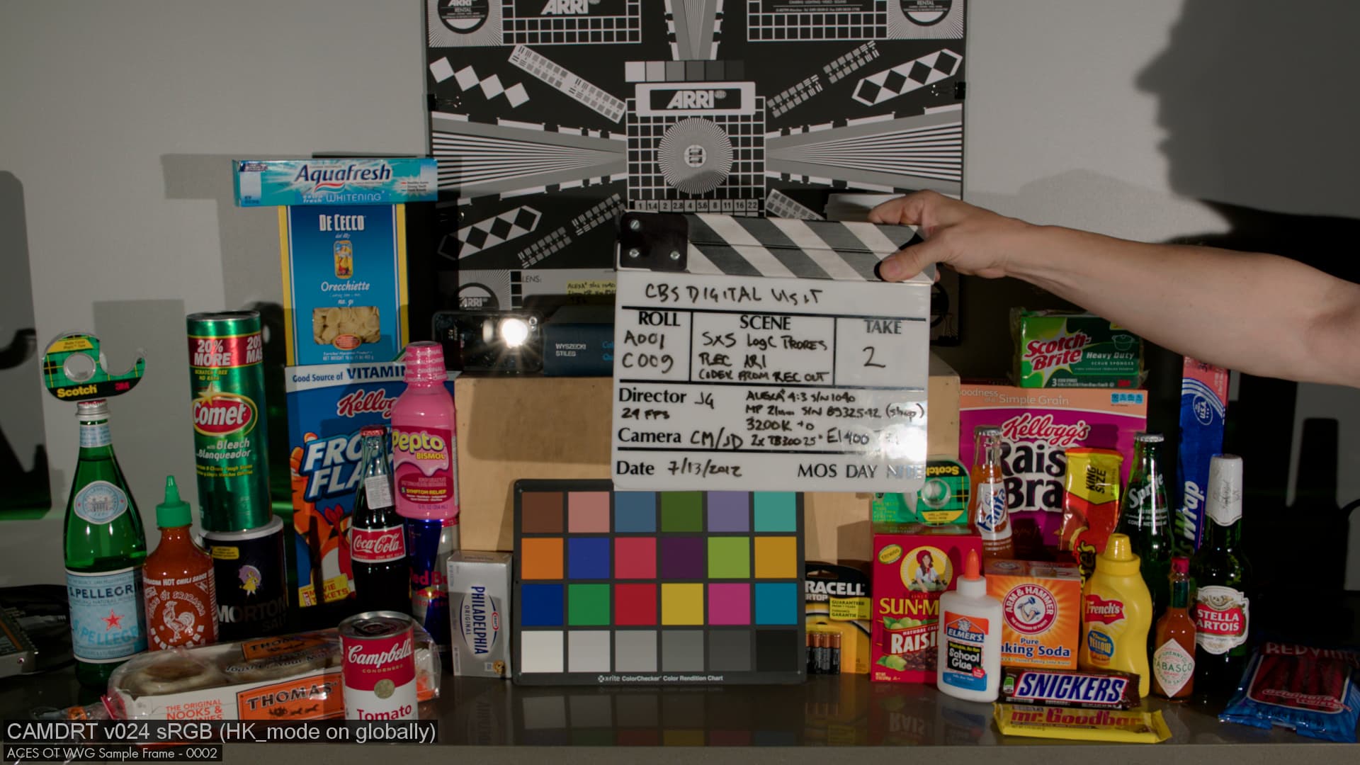
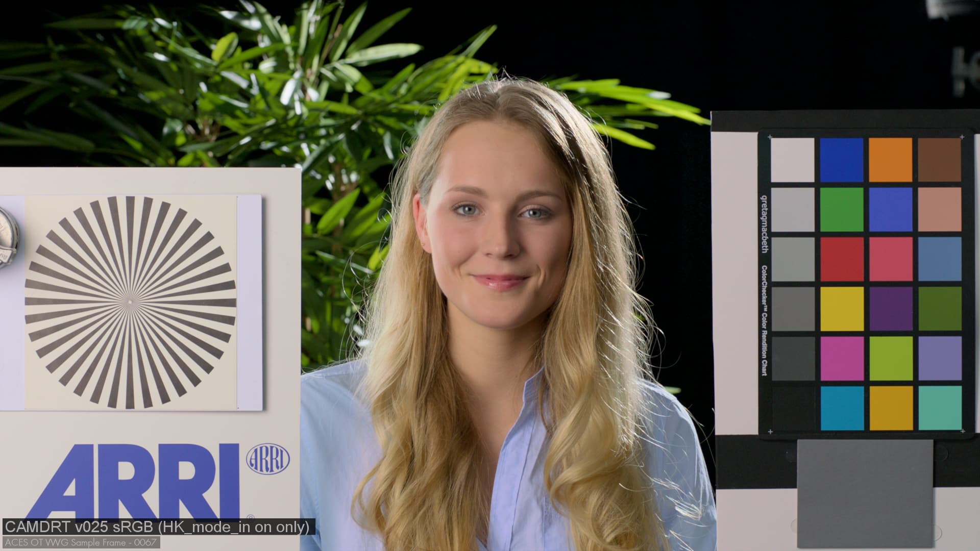
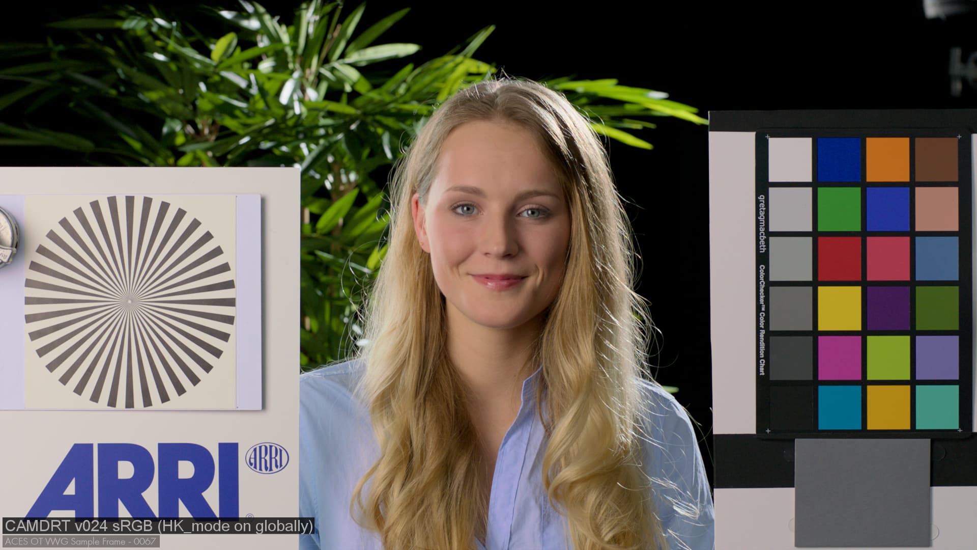
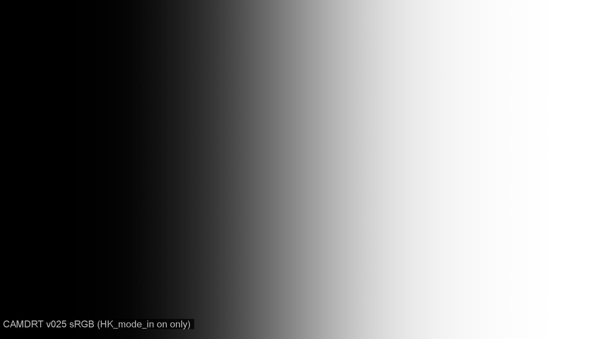
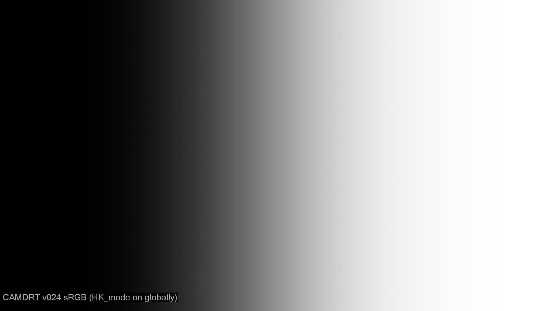
The is a new v025 that does a better job of allowing the XYZ_to_JMH function to be passed HK_mode and discountIluminant modes inderpendantly depeding on where in the DRT we are. It also incorporates a number of changes from @priikone which massivly speed up compile time.
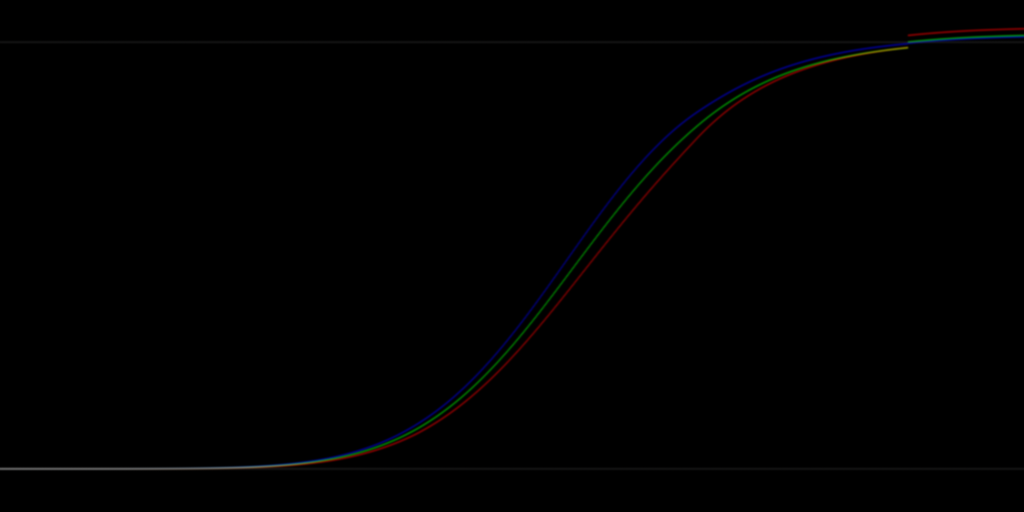
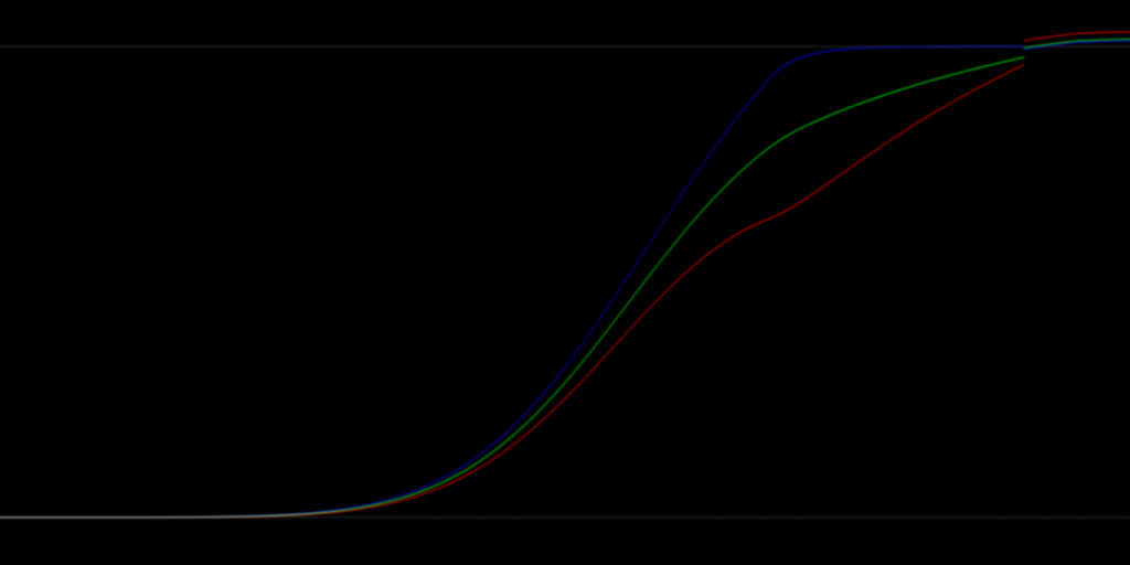
This first plot shows HK_mode enabled at every stage in the chain, resulting in the discontinuity.
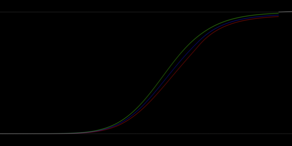
Whilst if I leave HK_mode only enabled for the entry in, as in the first transform from scene linear XYZ to JMh, but off for all subsequent transforms, we get a smooth result.
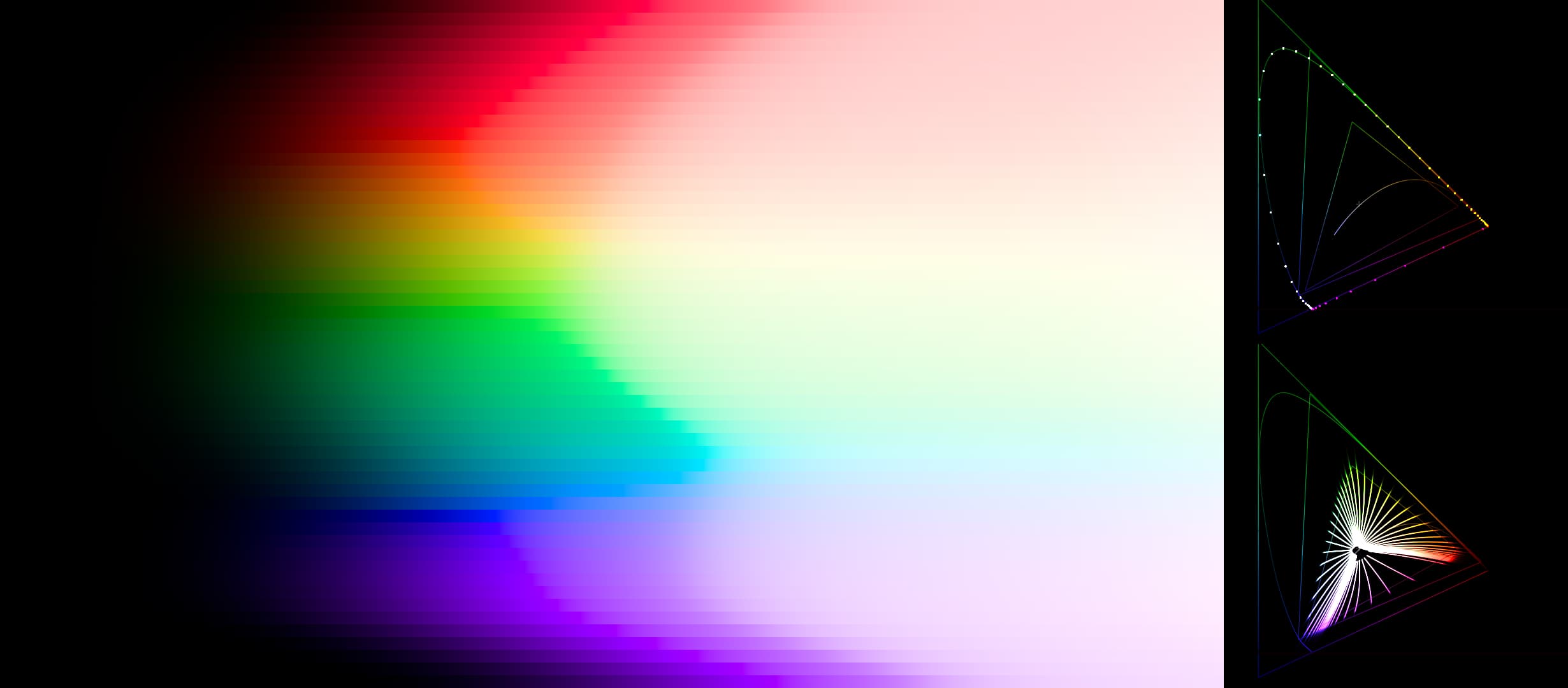
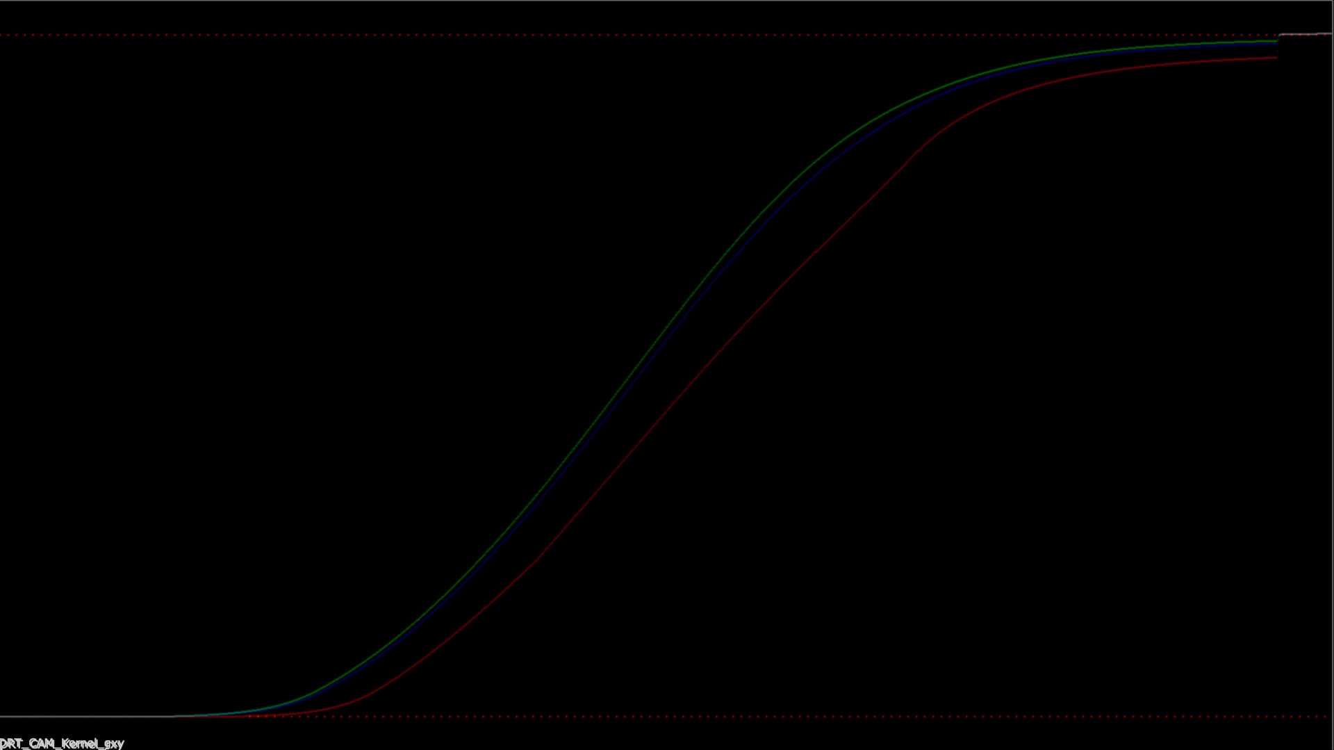
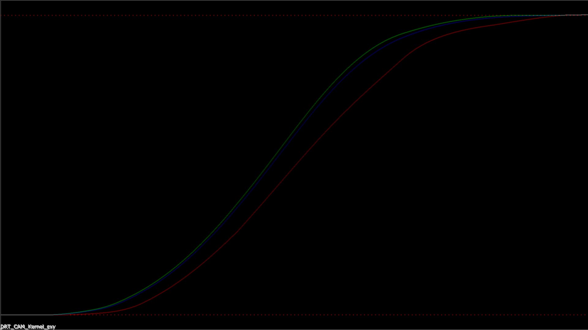
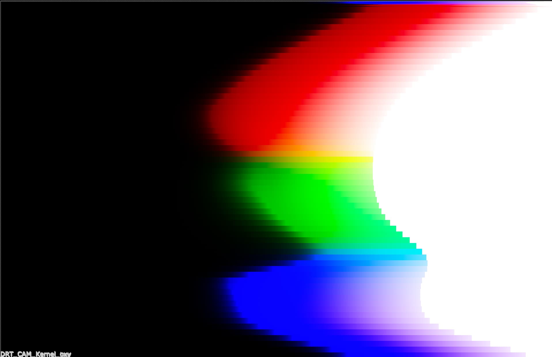
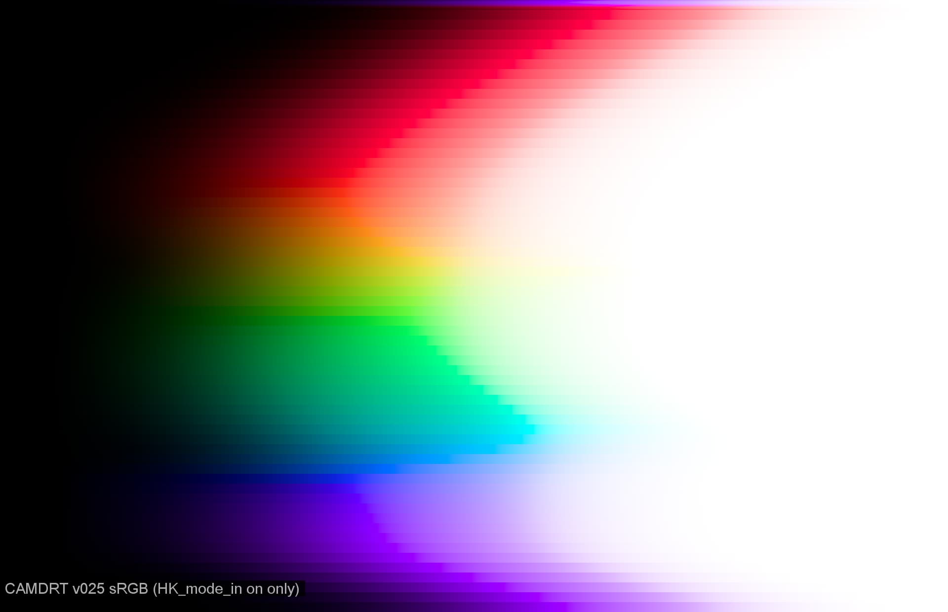
This second comparison shows the difference when rendering @priikone’s dominant wavelength ramps, which was always the easiest place to see “J collapse”. (with a massive post transform gamma down to make it easier to see)
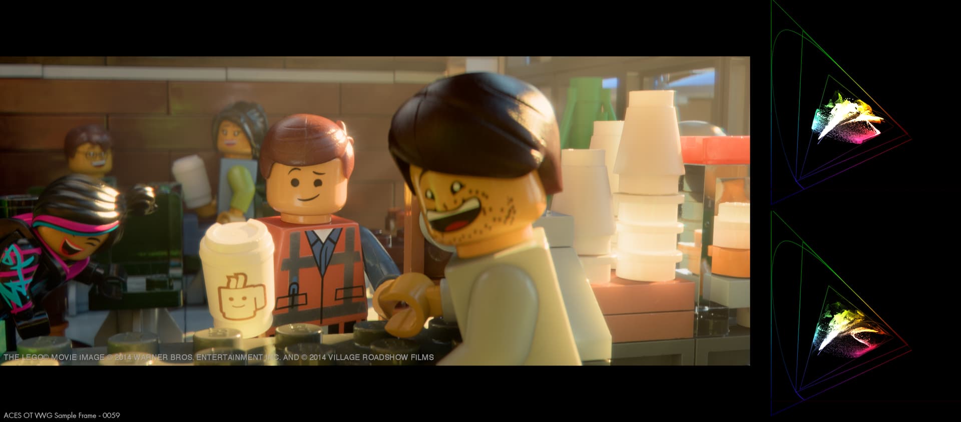
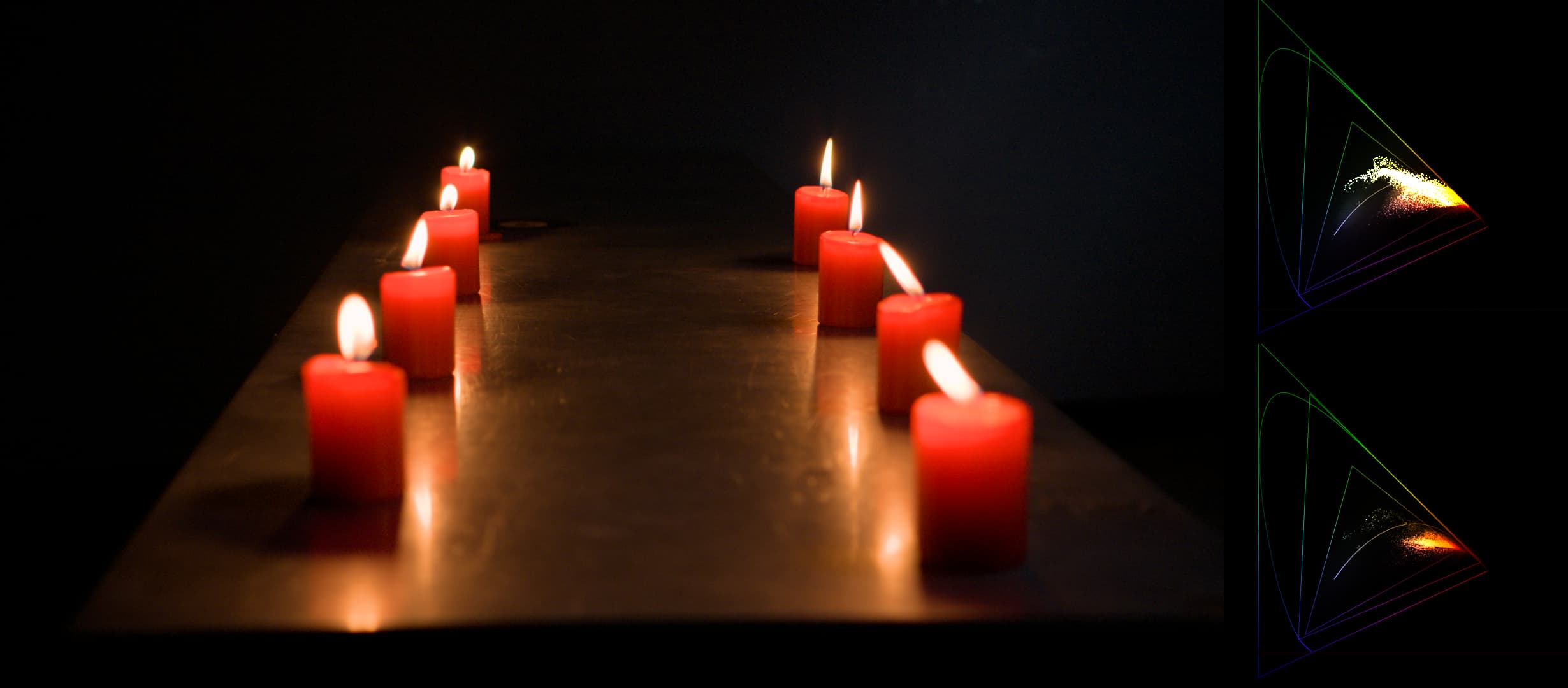
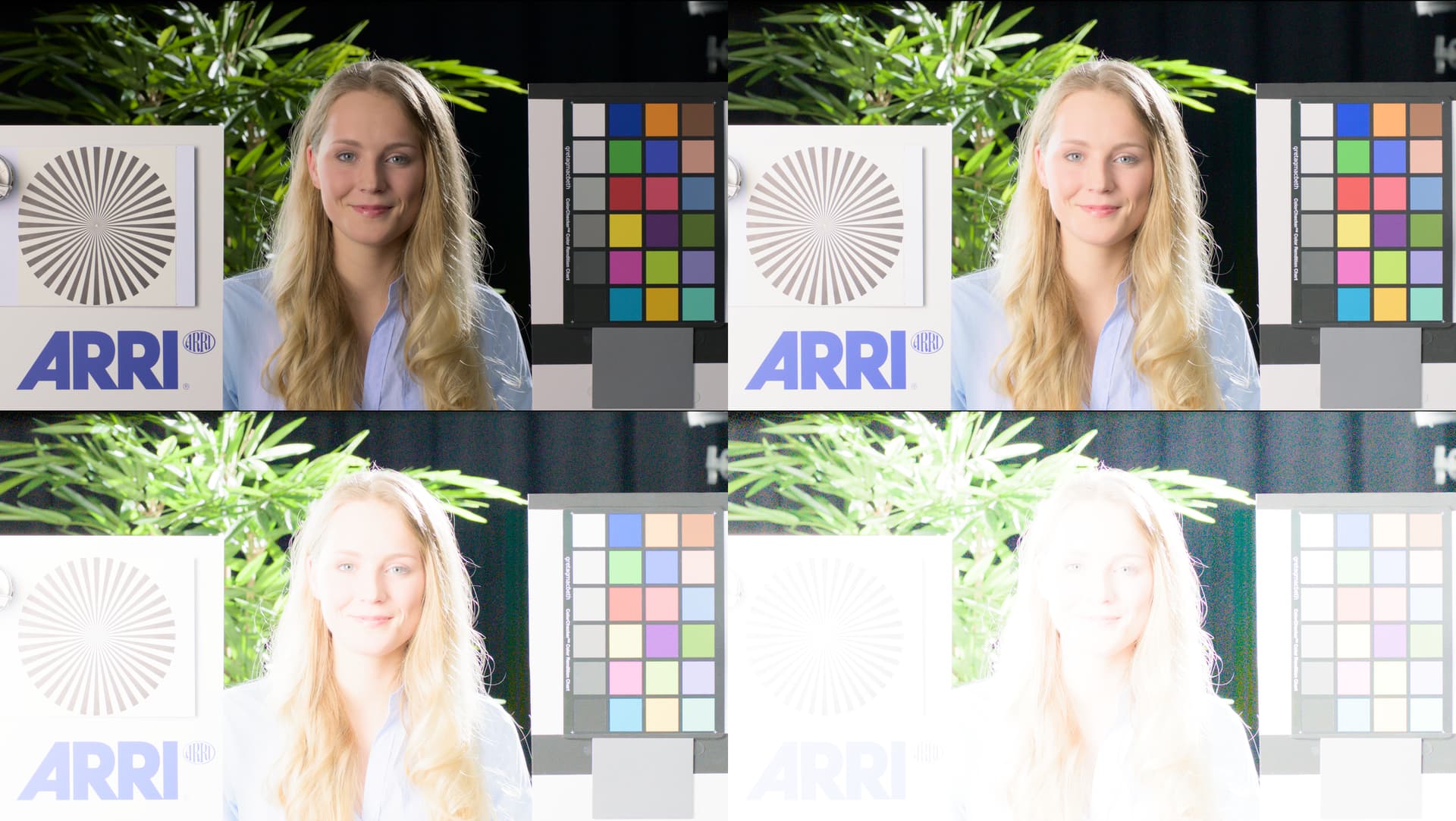
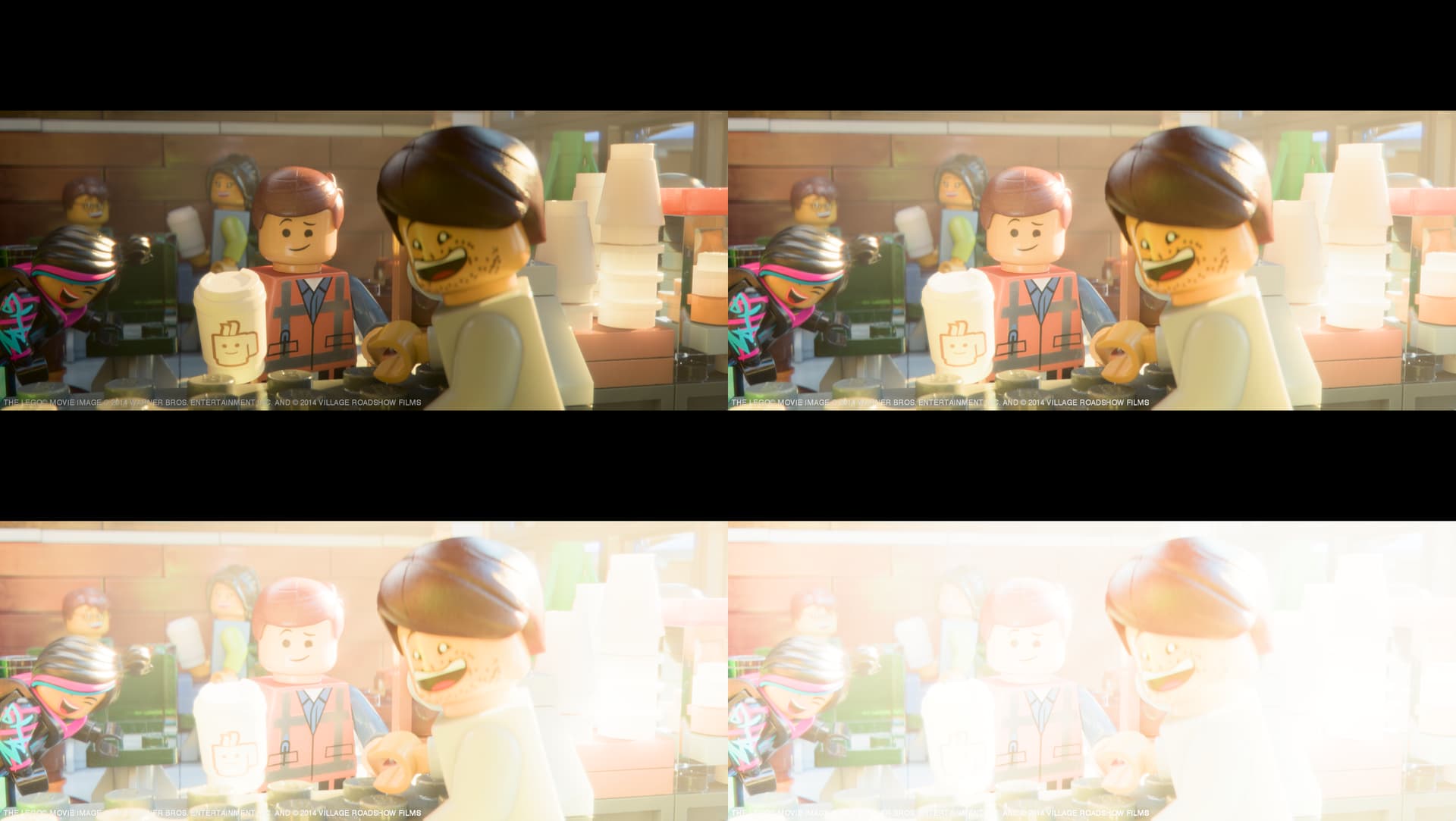
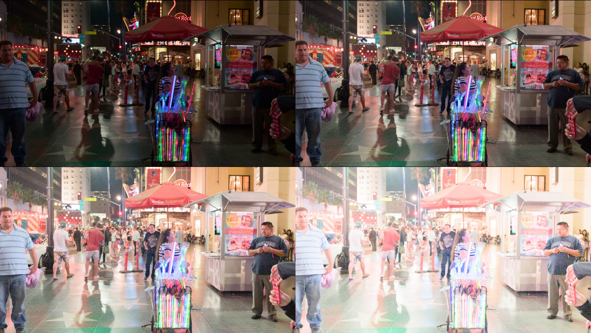
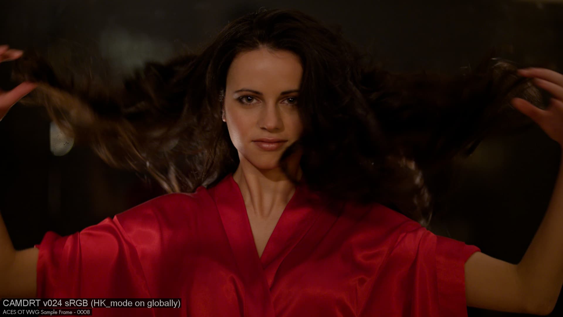
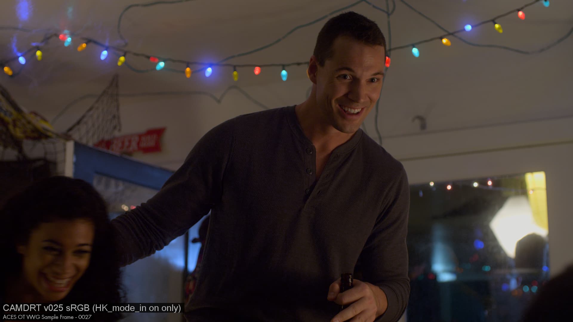
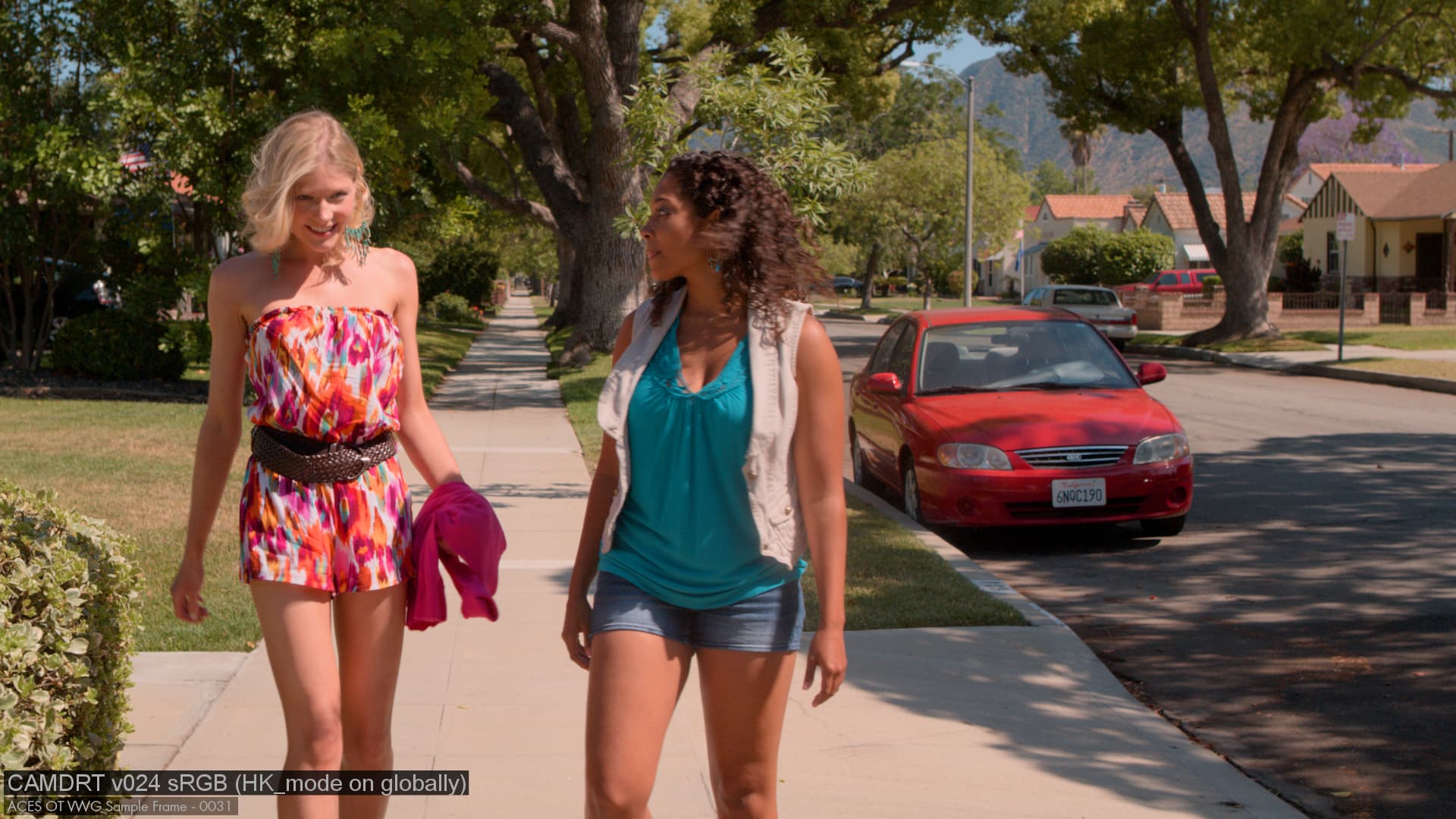
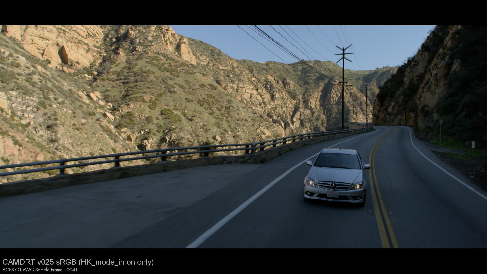
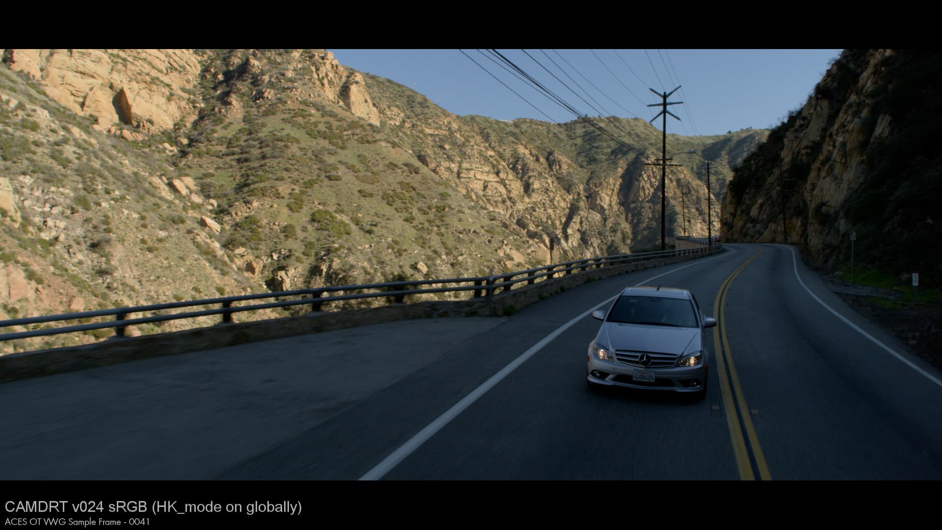
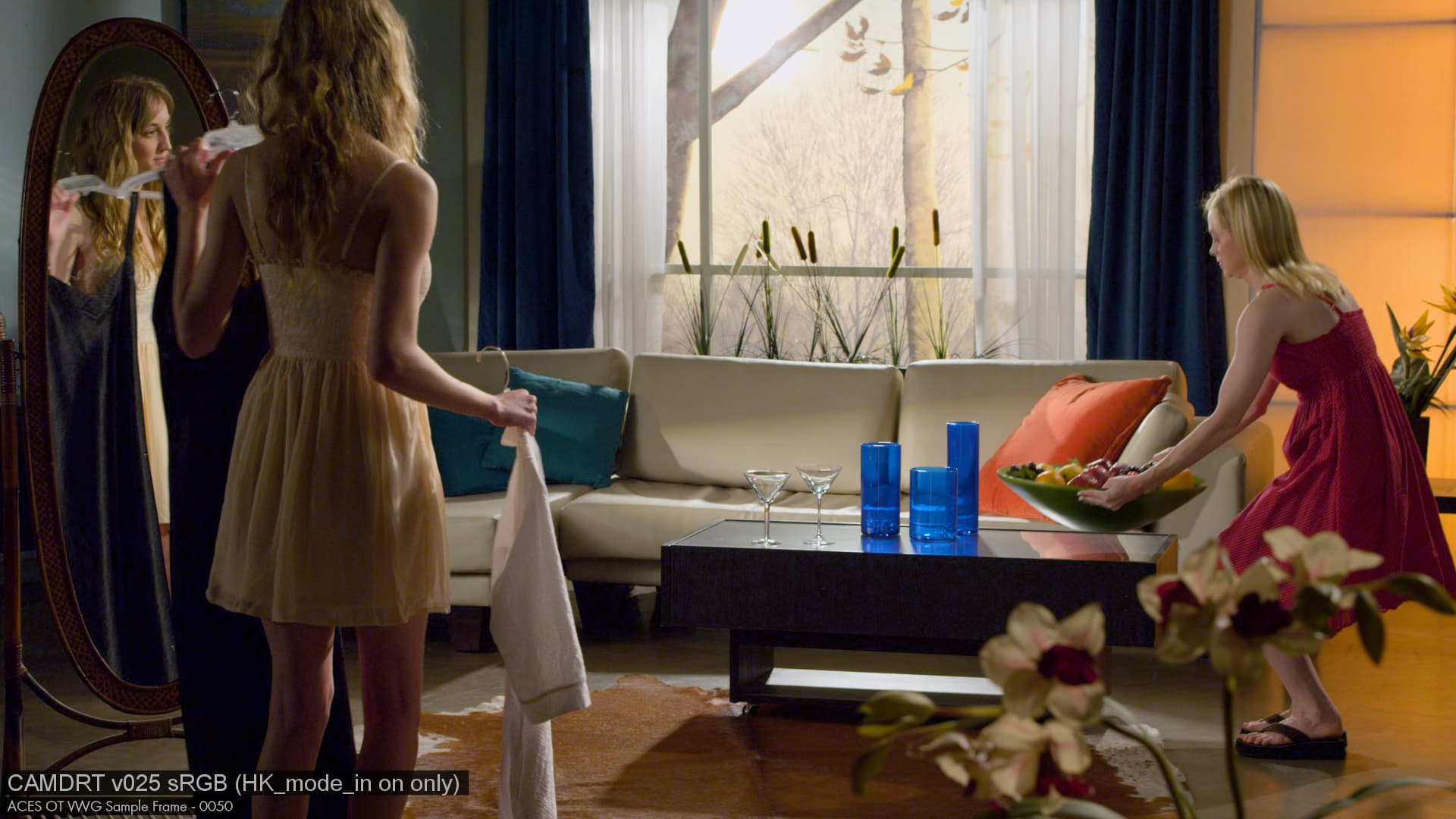
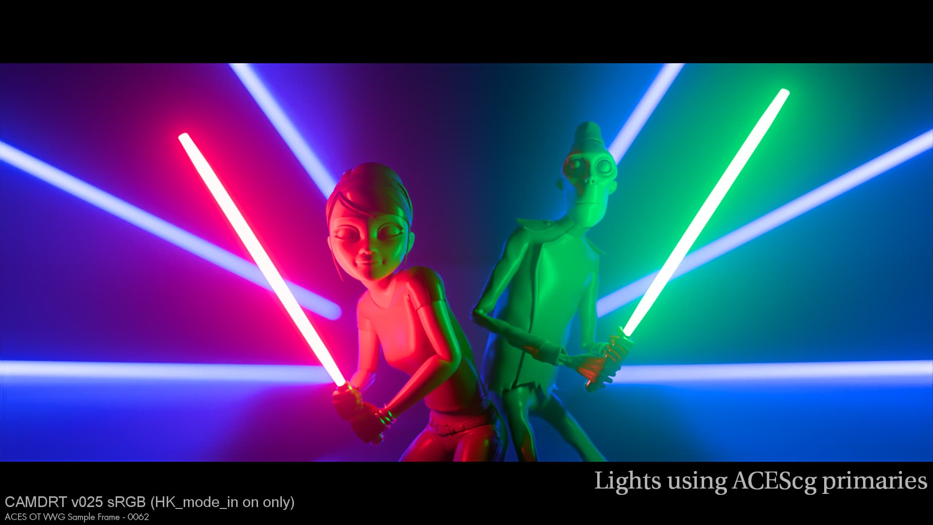
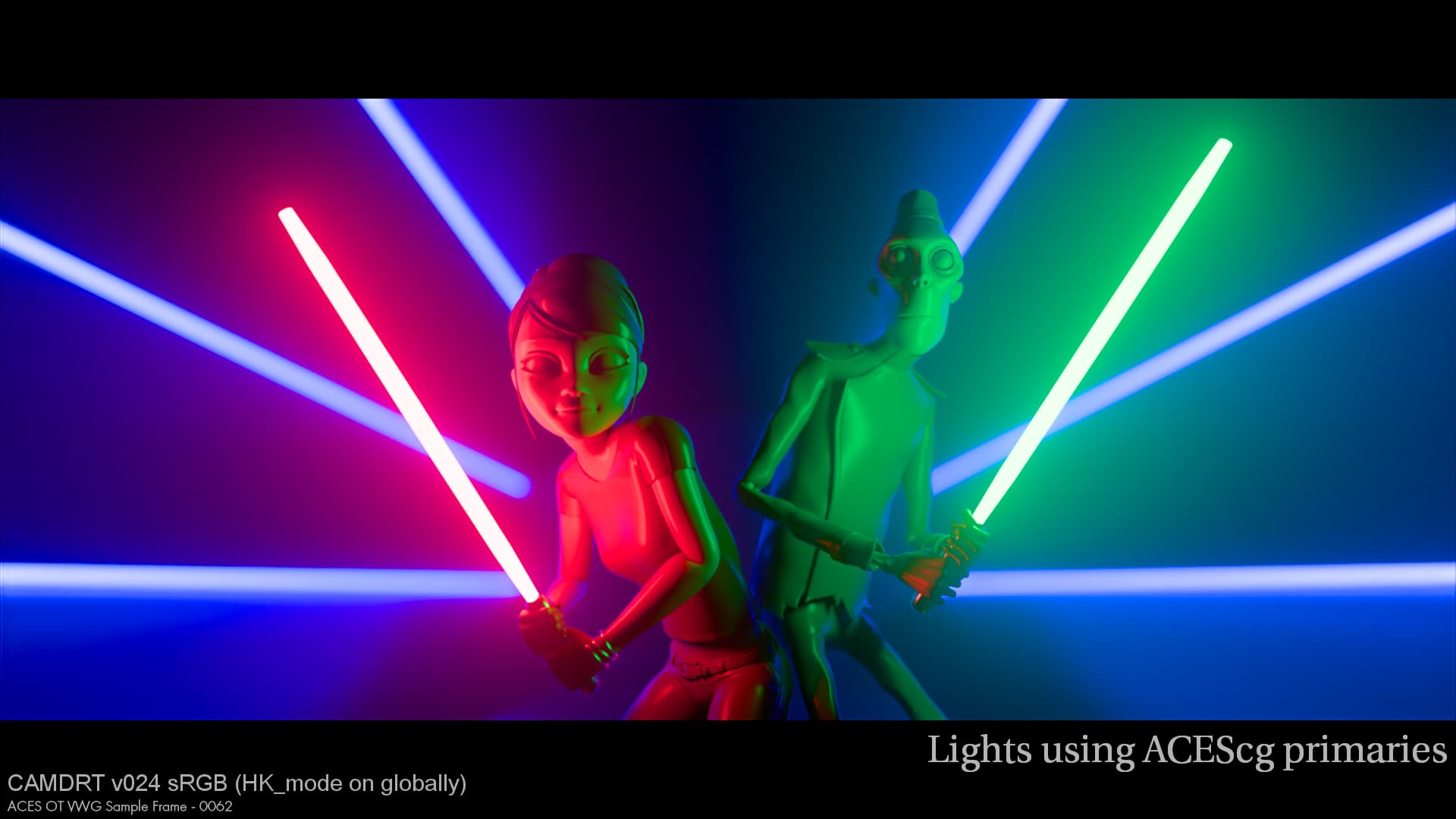
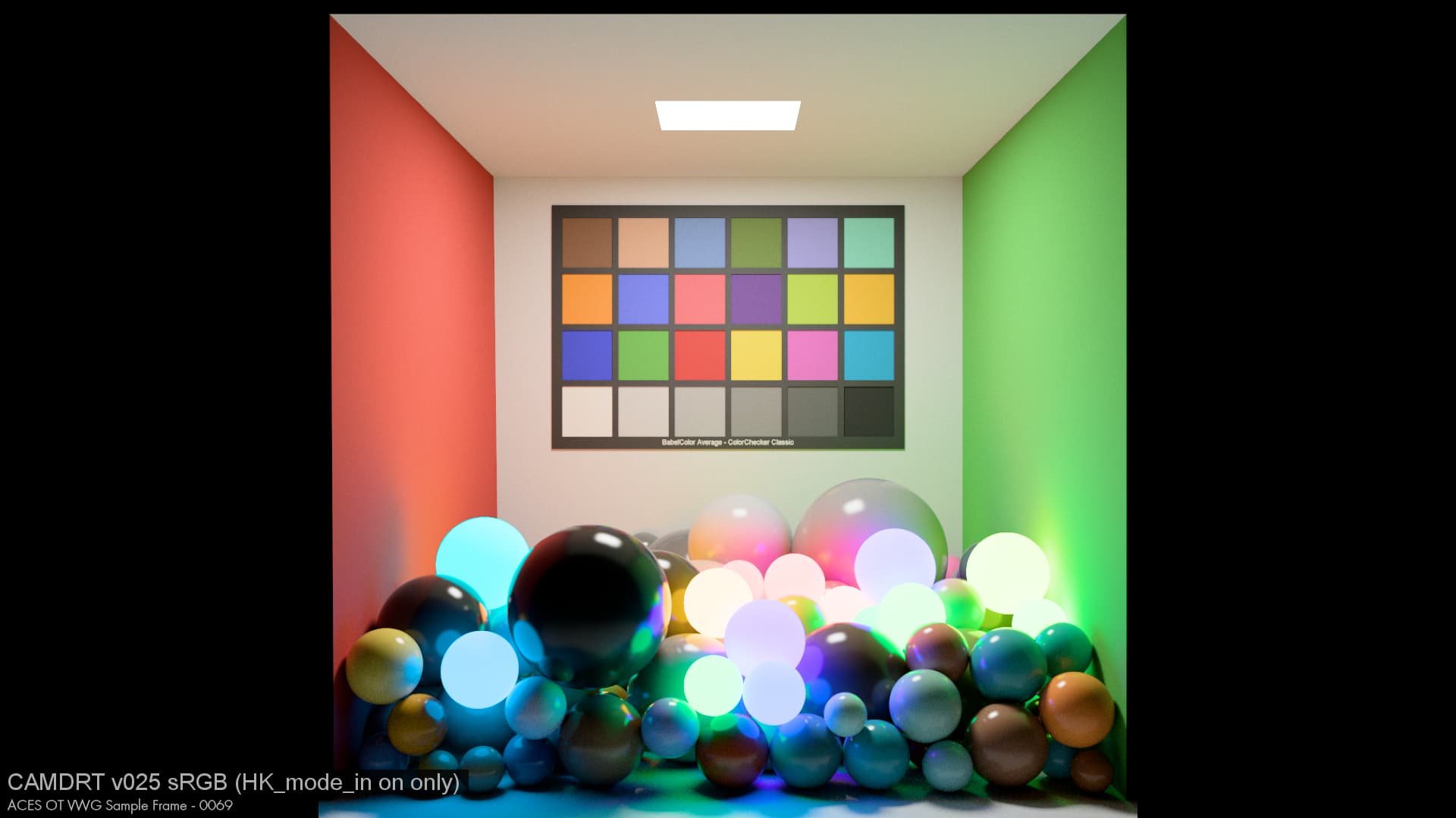
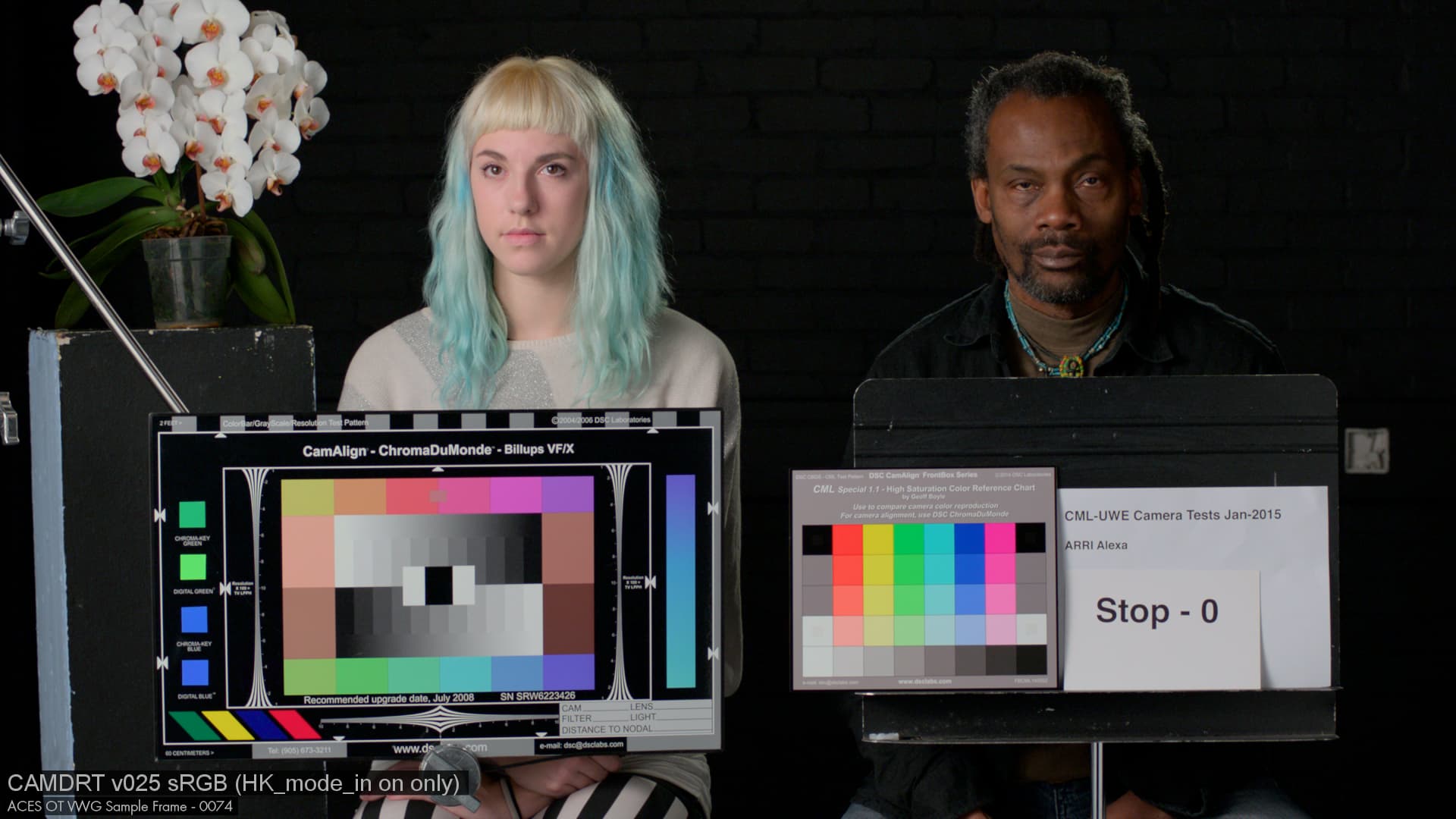
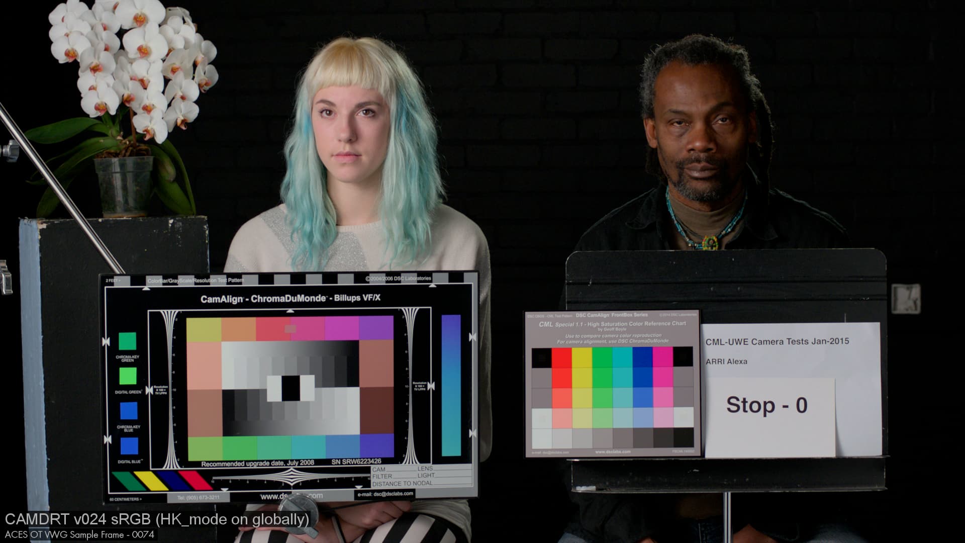
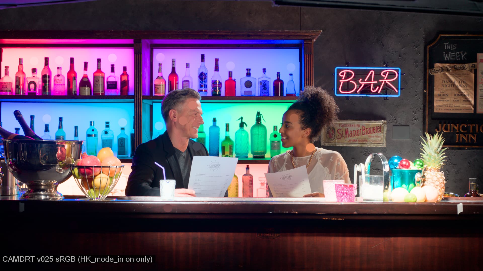
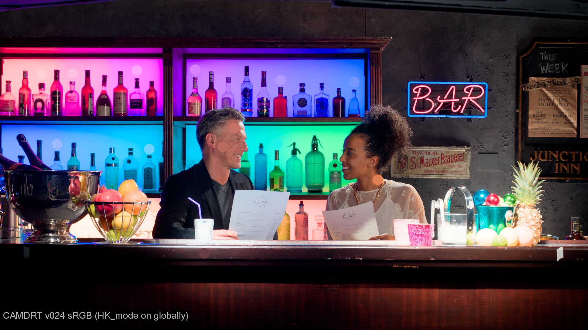
Now, this does change the appearance of the rendering pretty significantly, as this series of images below shows.
Pure greyscale values render the same, as seen in the grey ramp, but blues in paticular have higher brightness. I feels like the is a bit iffy when looking at the full blue patch on a macbeth, but feels like a win when looking at the brightness of the fairy lights behind Terry Silver on frame 28, which previously felt like it was suffering form the “nagative light energy” feeling we often get around highly saturated blues.
I’ve also updated the LUT repo with v025, but also left in v024 for easier comparison:
Great job, quick test shows it does fix the issues.
Do we actually need the discount illuminant? When it’s enabled doesn’t it mean we don’t do the CAT anymore from ACES whitepoint to D65, which both models expect? Shouldn’t it be disabled by default?