ACES 2.0 CAM DRT Development

Comparing SDR and HDR using v033
rec709
rec2100(rec709sim)
rec2100(P3D65 540nit)
rec2100(P3D65 1000nit)

SDR and HDR match much better then with v032 and are fairly good for most frames.
For example 0070 is a much better match than with v032.
I checked these with SDR on computer A and HDR on computer B as well as HDR on computer A and SDR on computer B.

Some issues were observed.

In most frames the rec2100(rec709sim) is not as good a match to other HDR as is the SDR rec709. The rec709sim seems to be not working as expected.

0012 Hollywood sign still red in HDR and more orange in both sim and SDR
0016 neon red as above^
0025 neon red as above^

0015 blue looks more grey in the rec2100(rec709sim) then either SDR or the other HDR
0033 same^
0035 same^
0046 same^

0017 still looks like clipping in the sun in rec709

0060 reds still look more orange in all (or maybe this is right?)
0061 same^
0063 same^

==================
INVERSE CHECK
With node as last time IDT and ODT toggled on and off.
SDR & sim
All the inverse IDT looked to work with v033 for SDR.
Very little differences in scopes and nothing really noticed in the images including the CGI frames.

HDR
Problems with green screen and the CGI frames but much better over all with some small differences noticed only in the scopes.

1 Like

Thanks Jeffrey for testing. I would agree and say that blue and red are the weakest colors when it comes to SDR/HDR match. It is the same with every previous version as well, as far as I have observed.

That’t really interesting. I suspect, however that the root of such a high order polynomial may be non-trivial to find. We can certainly look into it, but it may well be that because the power curve is only an approximation of the gamut boundary, a simpler function which gives a reasonable approximation of the intersection may be fine.

I’m a dumb dumb with math, so not sure how much use I can be haha, Which model did you use in chatGPT? I asked GPT4 and got this response.

The ChatGPT screen-shot I posted is a small part of a longer answer to my second question, “What if the exponent is not an integer?” My first question got a similar answer to yours, with the quadratic as an example. But we know we can easily solve those (it’s used elsewhere in the DRT). The exponent in our case is ~1.15, which is what makes the solution tricky. ChatGPT gave similar suggestions in the rest of the answer, that I didn’t show, regarding Newton Raphson, etc.

1 Like

I opened a new pull request for @alexfry for CAM DRT v034, also available in my fork.

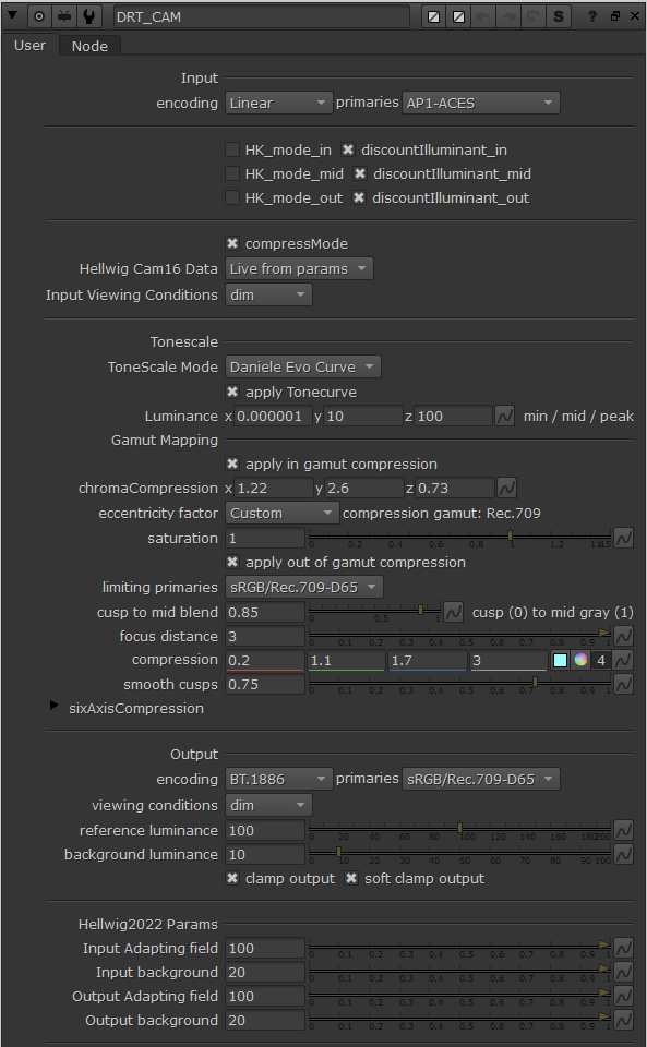
This version adds support for soft clamp to avoid clipping (enabled by default). In contrast to the soft clipping experiment I made earlier, which compressed both negative values and values above 1.0 in display linear, this version compresses only negative values in display linear. Values above 1.0 are hard clamped to 1.0, same as before. Inside the kernel parameters there’s clamp thr and clamp dist parameters to allow adjusting the compression threshold and distance.

This version also has a small refinement in SDR/HDR match. To my eye it’s now better than v031 was.

1 Like

Hi Alex,

while I answered to this post yesterday (OCIO 2 linear-sRGB VFX Workflow Advice - #3 by TooDee), I thought why not having a look how this rendering looks with the CAMDRT v033. It’s been a while since the first ODT candidates A, B, C comparison.


I used the baked LUT OCIO config to write out the JPG file, but I also compared it to the CAM_DRT_v033.nk script in Nuke 14.0v3.

At first I thought the baked LUT and the CAM_DRT node in nuke look identical, but when I lower the gamma in the viewer, the CAM_DRT is brighter in red and blue spheres (the upper split in the viewer).

Is this difference to be expected? I hope I did not make any mistake on the way…

Just in case, here is the rendering.
https://my.hidrive.com/lnk/1OUrl3CR

Best

Daniel

Merged, and the bake repo has been updated to include it:

1 Like

Hmmm… That is a bigger change than I would like to be seeing.
It’s not an extreme value either. I guess it just falling into an awkward spot in the cube’s lattice? Needs some prodding.

1 Like

That was the idea with this rendering in the first place.
It should work with nearly every display rendering transform. No negative values; all setup with linear-sRGB primaries; the main image content stays in a range roughly between 0-2 and the only high values can be found in the specular reflection of the chrome ball (approx. 9000).

Just finished grading a real project using ACES 2 v33 candidate. It was a commercial with lots of colorful clothings (it’s a brand that sells designer clothing). One thing I really liked is the presense of gamut compression in the darkest shadows.

2 Likes

Comparing SDR and HDR for v034:
Checked both SDR and HDR on both computers A & B described last week.

There looks to be pretty good consistency.
In the images with blues of sky and frame 0015 there may be a slight lesser saturation to make look a bit grayish, but no where near what I saw in v033. As stated at the last meeting, this may be from Resolve working with the LUT, however v034 is much improved.
Overall v034 looks to have the best fit thus far comparing SDR and HDR.

As to using the inverses for v034:
Overall the inverses seemed to work best when the colors are not far from the rec.709 space.
SDR inverses worked better than HDR.
HDR inverses failed in many frames, especially the CGI.

As a possible interest I found this presentation by Art Adams discussing ARRI’s REVEAL Color Science:

https://www.youtube.com/watch?v=s_RXjVeC_7s

Especially take note of when he describes the skin tones under various lights and the quality of colors.

1 Like

I mentioned in previous meetings that I was looking into my alternate approach to finding the gamut boundary for gamut compression, to make the gamut compression invert more precisely, and why that seemed to be causing a brightness shift in near-achromatic pixels.

I believe I have found the reason. Even when the colour is well within the threshold, so no gamut compression should take place, the code is calculating a value v which is the ratio of the distance of the colour from the J-axis to the distance of the boundary from the J-axis. It then compresses v, which will be unchanged if it is below the threshold parameter for the gamut compression (which it obviously will be for near-achromatic values). The final JMcompressed value is found as the proportion v along the line from the J-axis intersection to the gamut boundary. In theory for colours well within gamut this should all cancel out, and return the original JM value. However, for near-achromatic colours, the value of v is very small, and it appears to be processed in DCTL with insufficient precision to get back to the original value when multiplied again.

A simple 1D analogy:
\space \space \space x_{in} = 1.1
\space \space \space d = 100
\space \space \space v = \frac{x_{in}}{d} = 0.011

But let’s say our system precision only allows us to store v to 2 decimal places, so it becomes 0.01
The compression function does nothing to v because it’s below the threshold, so it remains 0.01

\space \space \space x_{out}=v \times d = 0.01 \times 100 = 1.0

So because of precision, dividing by d and then multiplying by d has the net effect of changing 1.1 into 1.0 rather than leaving it unchanged. The reason for this is not immediately obvious when you say you are working to two decimal place precision.

I therefore added an extra line to my DCTL implementation so it bypasses the compression entirely if v is below the compression threshold. This seems to have solved the problem, and is implemented in DRT_v31_709_alt.dctl in the latest commit to my repo.

I realise of course that this is still based on v31, so is behind @priikone’s latest experiments. As I have said previously, I will bring the DCTL up to date when things stabilise a bit more.

That’s similar to the old faithful

if (r == g && g == b)
    return unchangedValue;

but with an epsilon

1 Like

I made a pull request for CAM DRT v035 for @alexfry, also available in my fork.

This version is identical to the v035 prototype version posted in Alternative compress mode for ACES2 CAM DRT - #7 by priikone.

Changes:

  • Changes Hellwig2022 achromatic response formula and post adaptation code response formula to not includes the 0.305 and 0.1 offsets, respectively. This improves inverse with the current compression algorithm. See Alternative compress mode for ACES2 CAM DRT - #6 by priikone for more information.
  • Add Achromatic response slider to GUI.
  • Changes primaries to have slightly better blue SDR/HDR match
  • Includes @nick’s fix to gamut mapper. Pixels that used to come out as NaNs now come out as uncompressed.
2 Likes

LUT repo is updated with @priikone’s v035

1 Like

Been doing some tyre kicking on the sRGB vs P3 clip/clamp issue.

Both the image below are encapsulated within a P3 container.


Nothing conclusive, feels like we need to pump up the compression when we’re targeting a wider gamut, but it’s not obvious to me why. Looks like the same thing has been happening at least as far back as v028. Also looks much worse when we look at individual channels vs actual imagery.

Something we can talk through in the meeting more tomorrow.

I just tried v035 and get similar results for the solarization like issue mentioned in posts:

and

I did check where the cyan-green bottle ended up going in P3 and Rec.709. The scene values are highly saturated. The only difference seemed to be that Rec.709 was just the more compressed value, and so also the less saturated one and also darker. The P3 was more saturated and brighter version of the color. Below 2D diagrams, but I looked this in 3D too, and I think it was clear to me the Rec.709 version was darker because it’s compressed more. But I guess, in this case, it’s supposed to be compressed more.

Input:


P3:

Rec.709:

Input EXR in dropbox

So, following up on the discuission about brightness differences in sRGB vs P3 for highly saturated images, I’ve made some example images to help discuss the trade offs.

The image we were looking at was the backlit panels in the Arri 35 bar image:

The image below is a sort of side view JMh scope.
The lines on far right represent a JMh ramp from 0->100 in J, an M value of 118 (which is the intensity green from the image above), and a h of 169 (again from the image above)

The lines projecting in from that border show the angle and the distance the values move as they get yanked into the gamut hull.

Red = Rec709
Green = P3
Blue = Rec2020

And with a sweep of h:
JMh_SideSliceDiagram_distance3

The thing to note here is that whilst the angles arent radically different here, the extra distance the values have to move here to reach the 709 boundrey produces a larger drop in J.

This is not totaly unexpected. The original intention with this was that we wanted to trade some level of brightness to maintain more colour information. But this is a slightly subjective matter.

If we straighten the projection lines (by using a very large focus_distance value), we can better maintain brightness, but at the expense of colourfullness.

JMh_SideSliceDiagram_distance1000

The effect of this is nothing on images that exist entirely withing the target gamet, negligable on highly saturated reflective colours, and very noticable on high brightness high saturation colour like neon signs.

I’ve put a selection of images below to compare. It’s highly debatable which one is “better”, depending on the context.

The upsides of the linear (or near linear) projection is greater brightness consistancy between gamuts, and greater transmission of brightness ‘information’

The downside is once you’re above the cusp, we’re always sacrificing colour in favour of brightness.

Paticularly with the SDR/HDR match, it’s highly debatable which one matters more for any given image.

3 Likes