Yes I have. I observe the same differences in HDR as I do in SDR.
I did it in Nuke, so I’m afraid I wont be much help with Davinci!
Yes I have. I observe the same differences in HDR as I do in SDR.
I did it in Nuke, so I’m afraid I wont be much help with Davinci!
I agree with @Shebbe that the saturation for CAM DRT is great. I’m also not really sure that anything should be changed about red as far as its saturation or brightness goes.
What I would wish to adopt from ARRI Reveal for red is that red stayed red longer, and did not go to pink (path to white) quite as quickly as it does now.
For blue, I don’t think it should shift to magenta. Blue should be blue, a la OKlab.
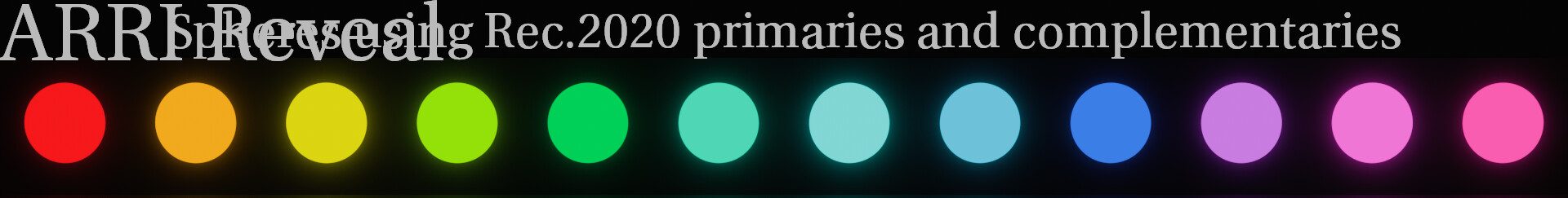
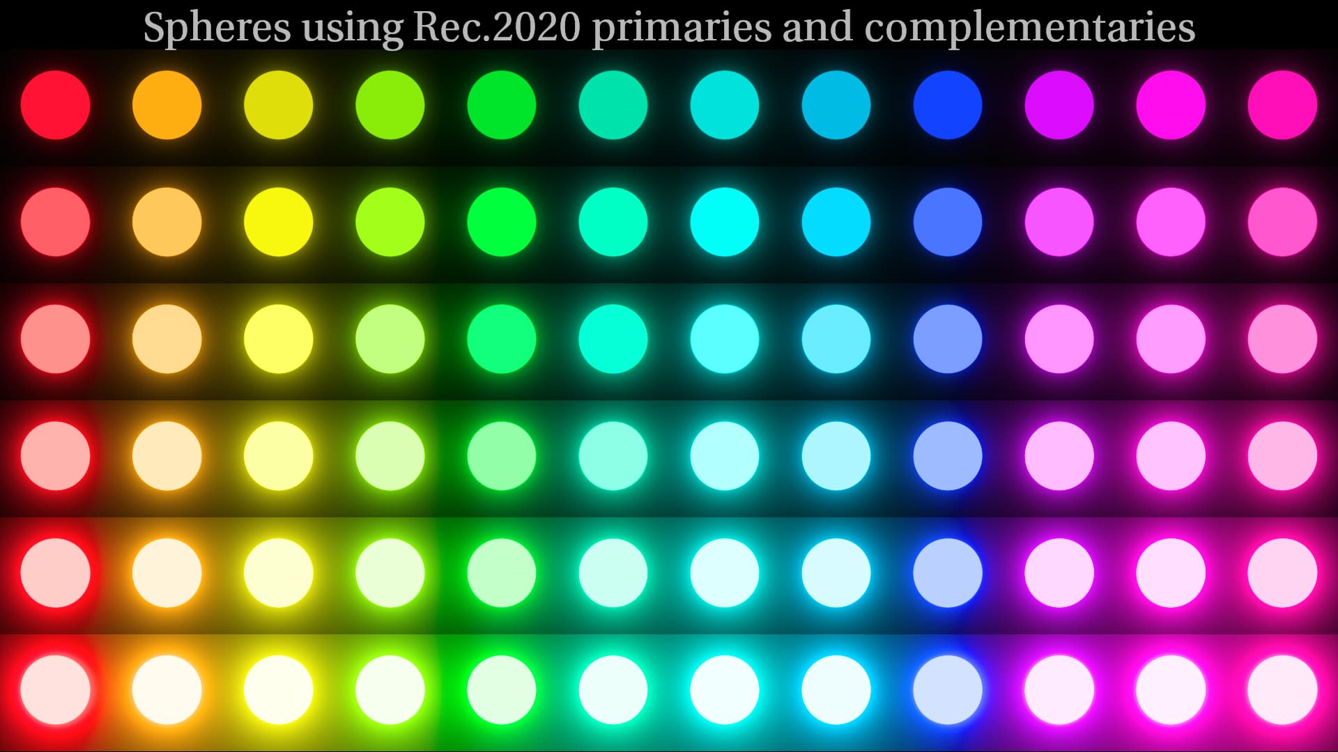
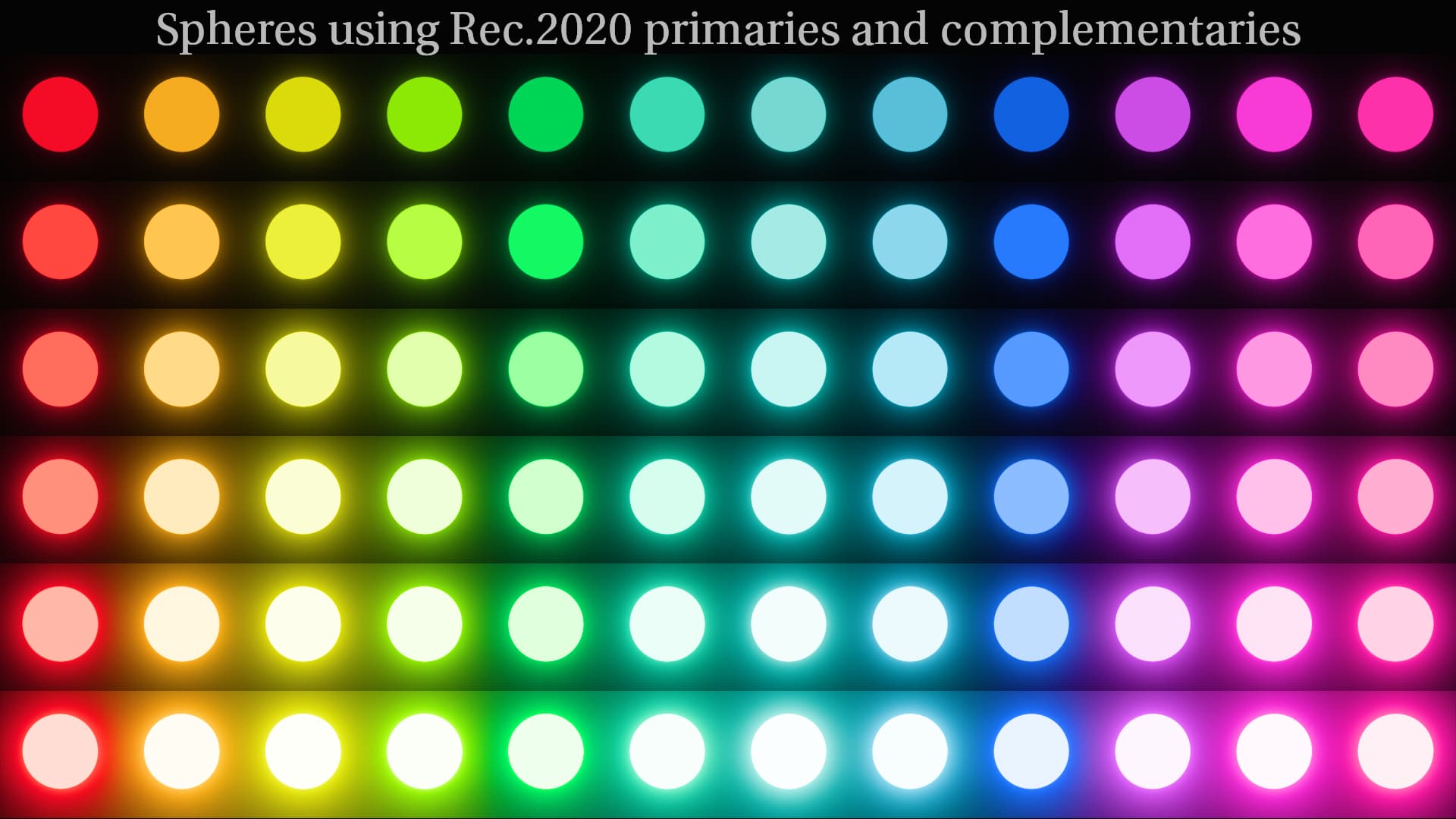
As far as the blues being brighter, that’s a discussion of color appearance. My observation is that looking at ARRI Reveal all these colors appear to me to have the same brightness:
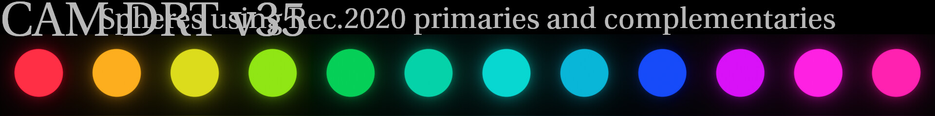
…and in CAM DRT the blue appears to me to be darker than the other colors:
should that be “fixed” in CAM DRT? I really don’t know, but I think it could be worth discussing.
Apologies that this is slightly off topic, but I can explain the difference.
The original ARRI LUT Generator web page could generate a range of LUTs. As well as the option to control the contrast of the curve, and generate e.g. a K2S3 LUT, the downloaded LUT sets included a “photometric” version, which used the underlying curve which mapped 0.0 in to 0.0 out and 1.0 in to 1.0 out, and a set of different “normalized” curves for each EI setting which rescaled the curve to set the black level, and ensure the curve hit 1.0 at the exact clipping point at that particular EI.
The EI dependent version was what was applied on the monitor output of the camera, so I always thought it slightly odd that the photometric K1S1 became the default used in post, as it doesn’t exactly match what would have been seen on set, and has a rather raised black level. I guess ARRI thought the same, as what they now ship as the “classic” LUT appears to be more like the EI800 variant, which I always considered a better default.
End of sidetrack!
Ahhh!!! That explains a lot!! Thank you!! ![]()
Thanks again for your continued work on this Nick, this appears to be one of the most critical steps in the whole transform, so any and all tweaks need to be tried.
The part that hurt my head the most with the P3 clipping and the 709 not clipping the green was not that the different gamuts gave different results, it was that 709 Limited P3 gave different results in P3!
The idea to blend the two images was not immediately useful to fix the problem, but it suggested that an intermediate abstract gamut might be a useful idea.
From the perspective of 709 limited P3, the 709 is just an abstract gamut, so maybe another “ideal” abstract gamut could offer the desired properties.
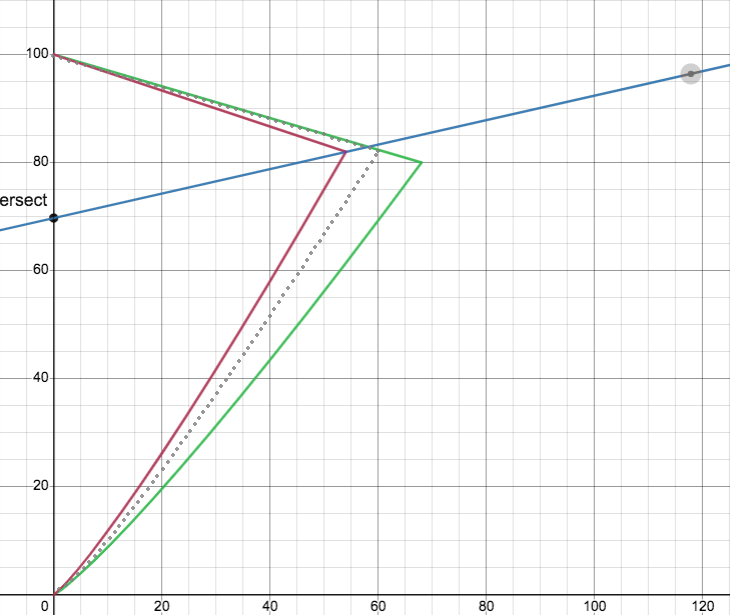
here are two examples, roughly based on 709 near “Arri Bar green” (P3 cusp is not accurate, but could represent any larger display gamut), and the sample is roughly “Arri Bar green” values for reference.
The first is very simple, close to an average, but it specifically has a cusp with a higher J value than 709.
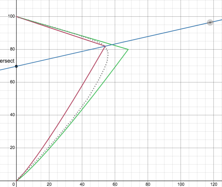
The second one was done with a simple bezier (not sure if that is too complex for current options), but something like that may help with smoothness.
Only suggesting any of this because the gamut mapper appears sensitive to the cusp position and the results from P3 were so unintuitive compared to 709.
Probably not a solution, given the requirements to map to any display, but the idea has come up a few times so it might be a useful experiment to see what an adjusted “virtual cusp” might have on the output.
At the very least, It may help determine the ideal behaviour of the gamut mapper.
This is what’s happening with the current transform by default with the cusp smoothing enabled. The actual shape for the gamut mapping intersection is a rounded shape like the one in your example.
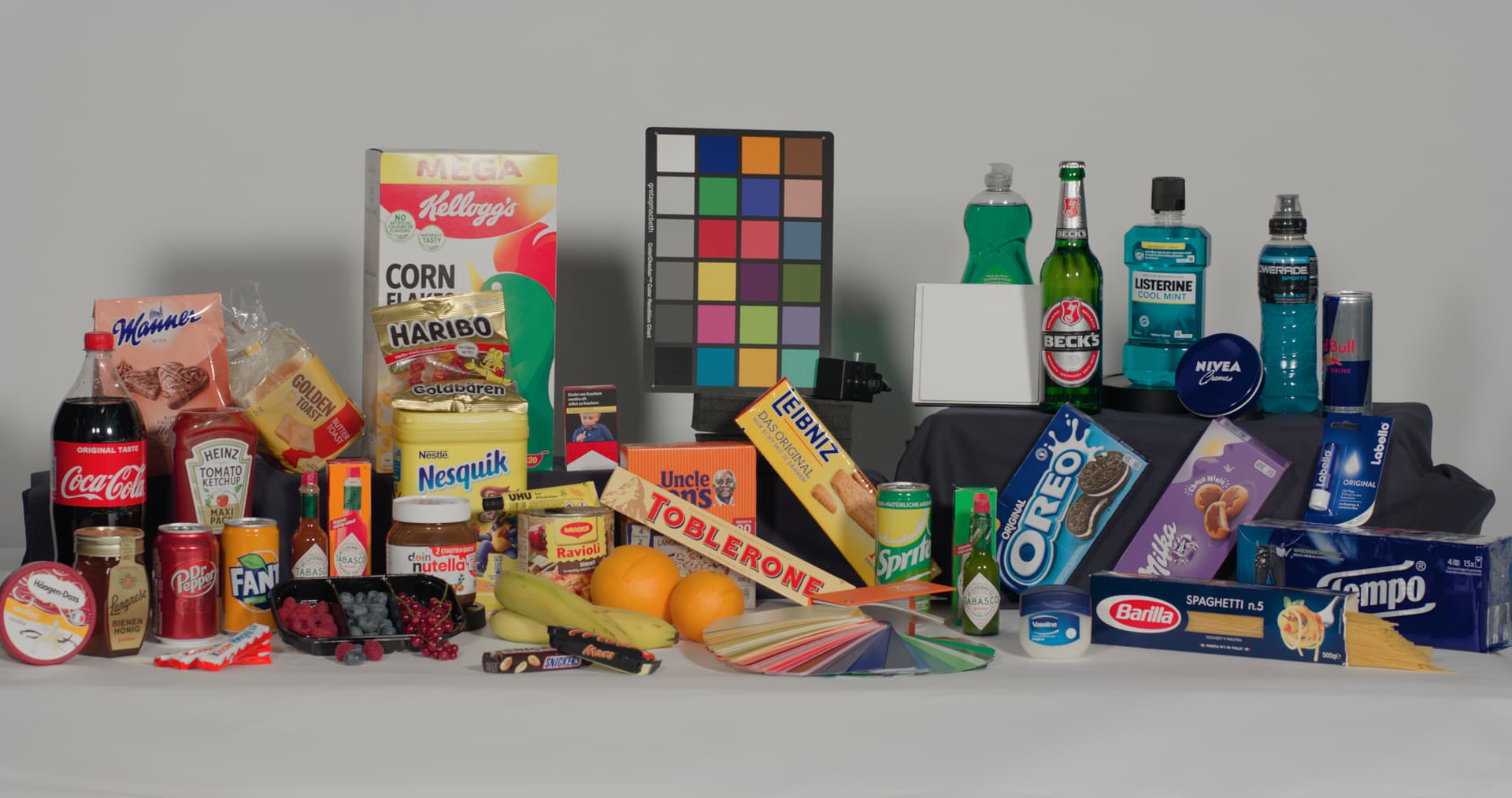
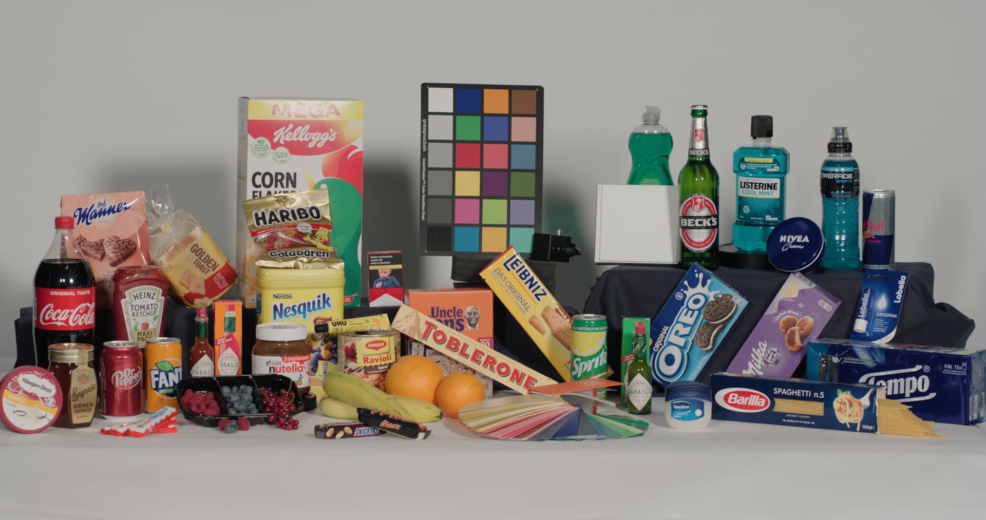
I tested using P3 as the limiting gamut for Rec.709, clipping the end result to Rec.709. As expected, the image mostly looks the same, and fine, but there are more “traditional” type skews, and especially visible with green. Here’s few comparison images. First image is v035 Rec.709, second is v035 Rec.709 with P3 as mapping gamut, and third one is ARRI Reveal Rec.709.
EDIT: When comparing this change to P3 rendering, I noticed the Rec.709 match is visibly closer to P3 colors, including the highly saturated green.
Hi Derek,
how and which type of HDR did you render out from rev035?
I tried to use the OCIO config, but I did not had any success yet.
I usually take the 1-1-1 tagged QT in FCPX and use a colorspace override to see the result in HDR. The transform in the OCIO config does not even specify if it is HLG or PQ. I am confused.
With the OCIOv2 studio config from Nuke 14 this workflow works without any issue. Same for ARRI Reveal via a LUT or Truelight T-Cam.
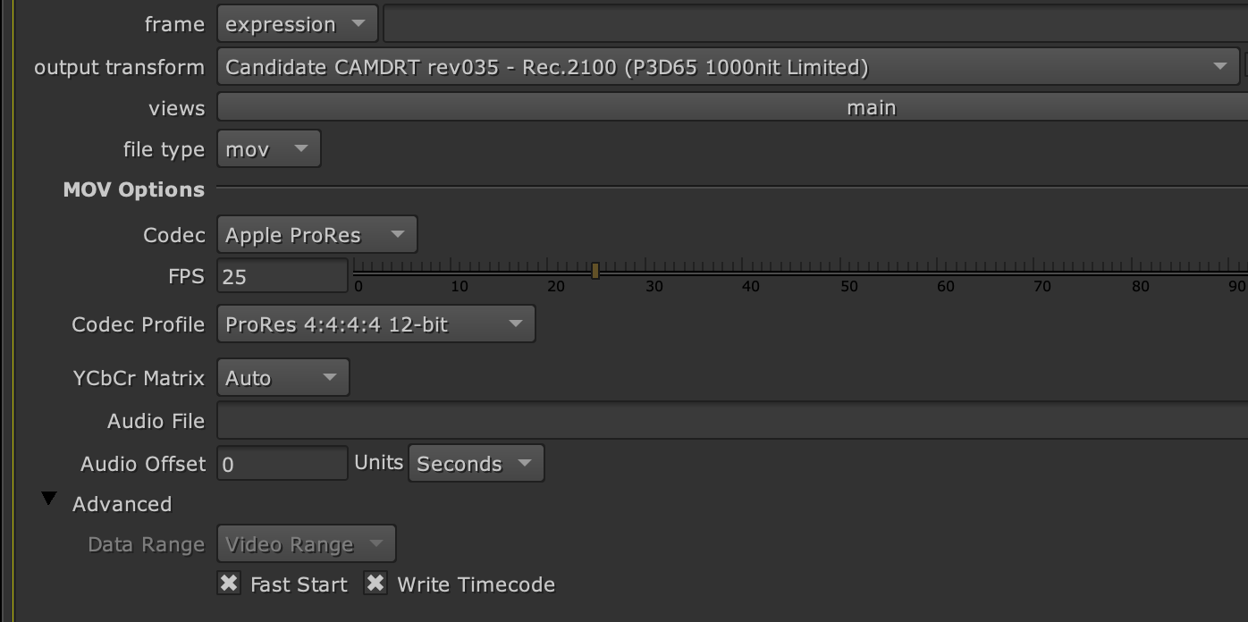
Additional failed test:
I was hoping to render out a HDR file with these setting. But no success. At least I know that it should be PQ and not HLG.
@alexfry Do you know what I am doing wrong?
Hi Daniel,
I’m probably not going to be able to help much with this unfortunately. I’m not writing out to HDR, but simply viewing the HDR on my Mac Pro M1 from inside of Nuke.
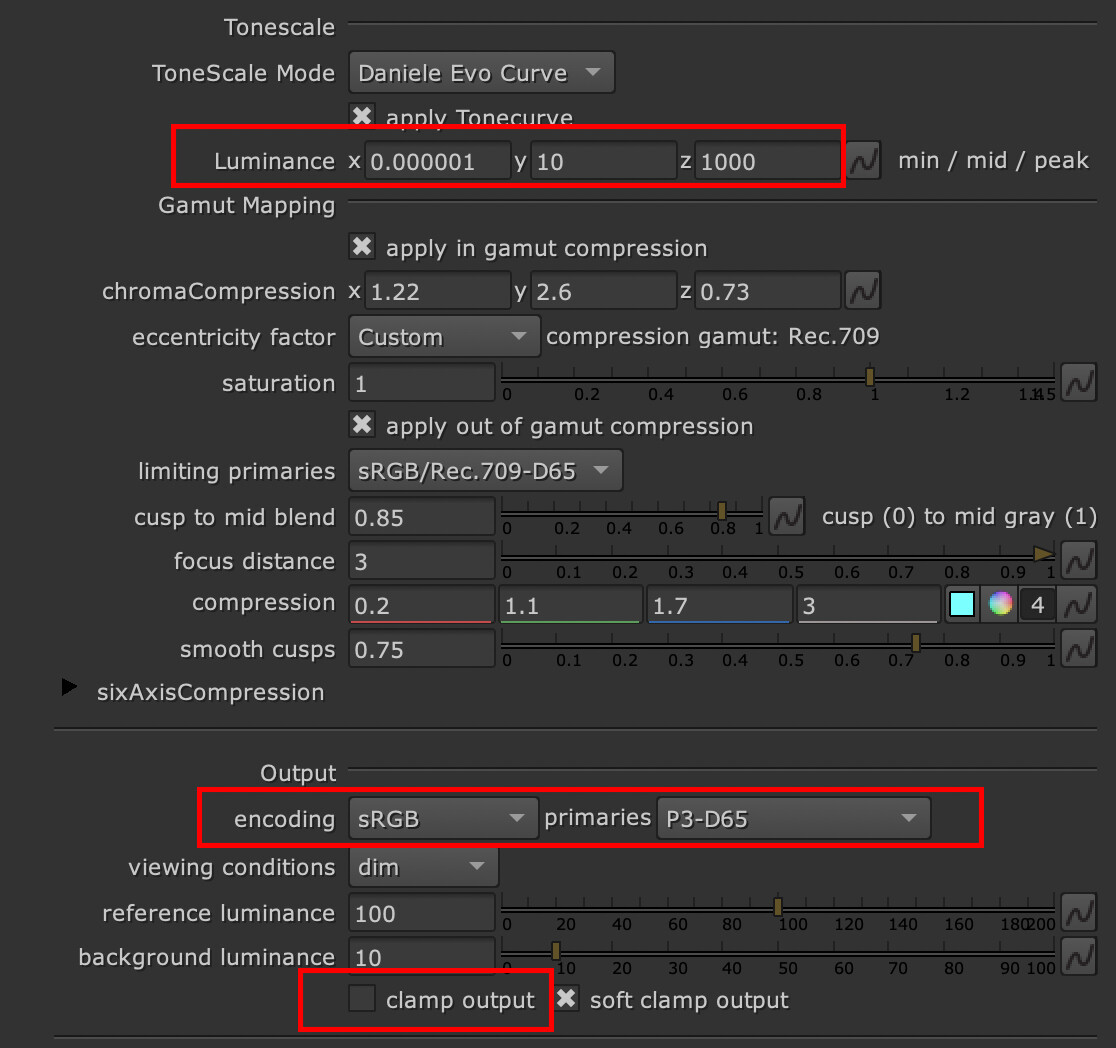
In case it’s helpful, in Nuke I’m using the Nuke node for the CAM_DRTv35 and have it set to 1000 peak luminance, output encoding sRGB/P3-D65 (which is what a MacPro uses, but would be different in your case), and clamp output off.
ah ok, thanks Derek.
1000 nits peak makes sense of course. I oversaw this setting.
But the result clip still looks wrong. There must be another value missing for PQ HDR.
I wonder why I am not successful with the LUT from the OCIO config.
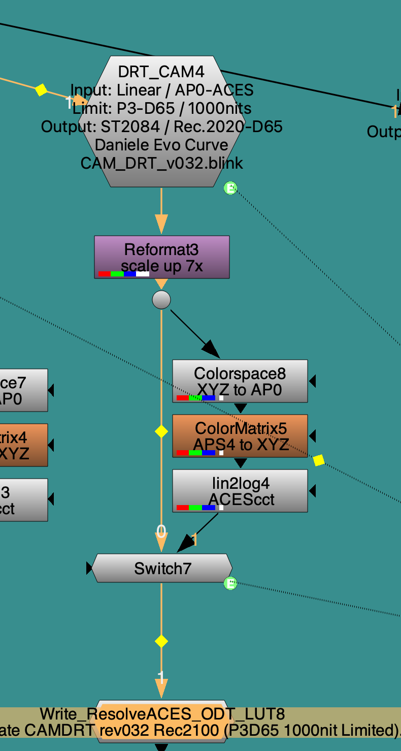
Might help to have a look at the OCIO bake LUT script on @alexfry 's repo to see how those LUTs were made. Here’s a screenshot (from v32):
Hi,
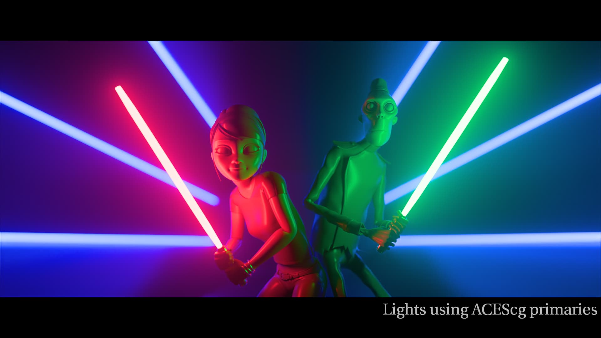
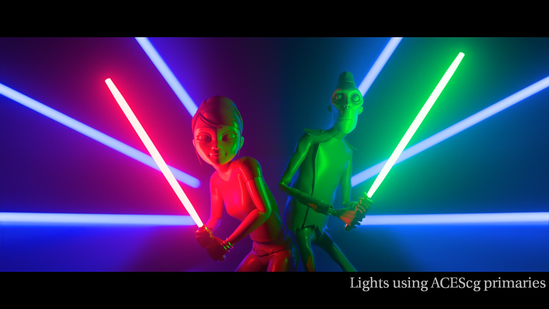
I remember in the meetings it was mentioned that blue turns magenta in some occasions like in the blue bar or in the rendered blue light cone.
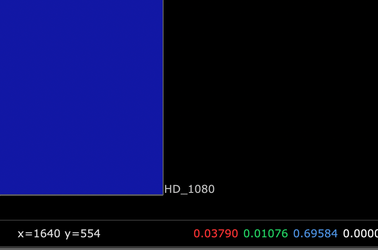
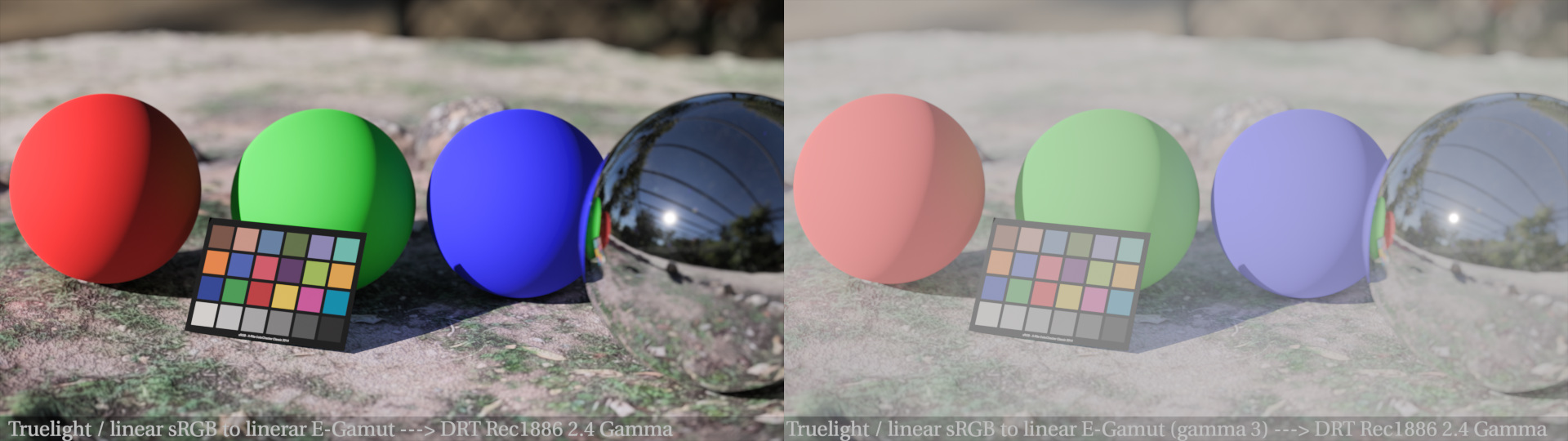
I have a render that I put though the LUT version of v035 and I noticed magenta where should only be blue in image.
The blue sphere shows a magenta highlight and with a lifted gamma before the LUT the whole sphere looks magenta.
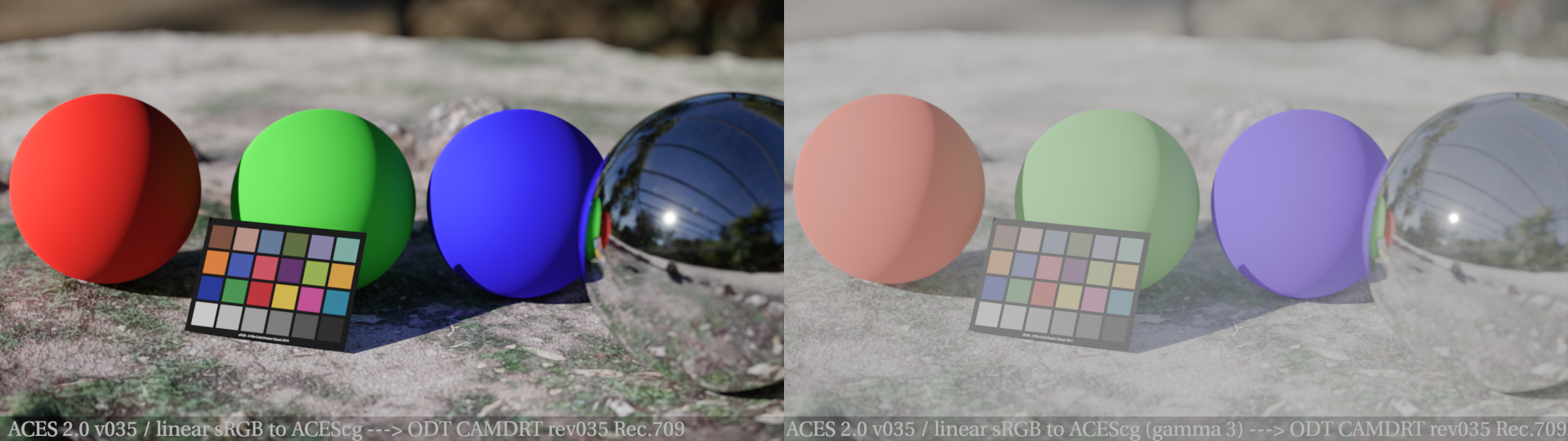
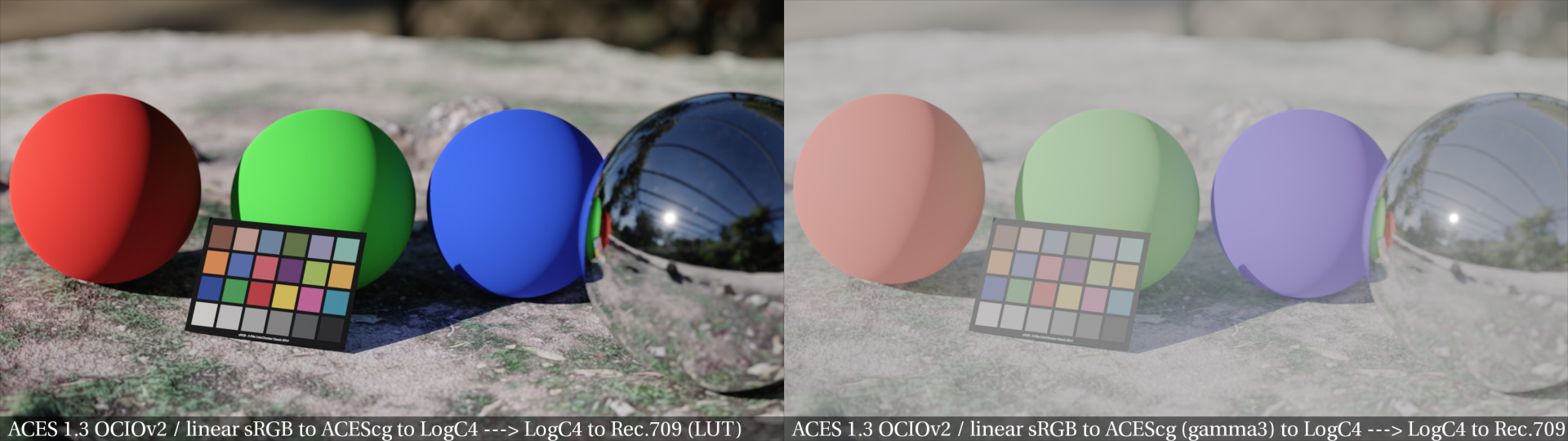
The rendering was done in linear sRGB and after a while I might realised why this happens. The base color shader value is set to 0/0/0,800 in a principled shader. By converting the primaries in Nuke from linear sRGB to ACEScg, the pure tristimulus values in the shader and in the render get a new meaning in the EXR values in ACEcg.
The linear sRGB 0 / 0 / 0,800 value turns to
If I simply interpret the EXR rendering as ACEScg, everything becomes more colourful and wrong, but the blue sphere stays blue in the output.
I wonder if this also happens with some of of the camera footage when it is converted from camera color space to the working space.
Just for comparison I rendered out some more view transforms from the same rendering:
I wonder what ARRI and T-Cam are doing different that I end up with a blue sphere as I intended to render in this case.
Actually the HDR versions look quite different. I will post them as soon as I can output a HDR version from v035.
I don’t know the LUT’s are baked, but ACEScct seems an odd choice at a first glance.
It’s the ACEScct curve, but using my super wide “APS4” primaries
ok,
so I assume I should interpret the rendered ProRes from Nuke with the HDR-LUT as PQ. I did not had any success with it yet.
Sorry, I made a mistake on my end. I figured it out now. The clip was in PQ, but I reviewed it in a HLG timeline. ![]()
Thanks for these examples Pekka.
I imagined the cusp smoothing as “effectively” the same effect, but can it be easily be constrained to the gamut boundary of a particular display?
I ask this because I thought it was implemented (or a version of it) long before Nick’s gamut boundary target/algorithm was implemented, or has it been re-configured to operate in/with that step?
How exactly does the cusp smoothing interact with the boundary finding algorithm?
My idea of trying some in-between abstract or “virtual display” primaries was mostly to serve as aid or diagnostic to help modify the settings/behavior of the compression since it is responsive to (and quite sensitive to) the position of the cusp.
We have more or less expected behavior in Rec709, but less than expected (not necessarily “bad”) with P3. May not be the biggest problem, but I am still curious what is required to get less clipping in the P3 output, and of course having more control or understanding of the boundary finding/gamut compression couldn’t hurt.
Christopher
After I figured out how to interpret the nuke ProRes from Nuke in the right way in FCPX, here is a HLG playout of the same rendering in four flavours:

This clip plays fine for me as HDR in Safari on an iMac display and on Apple XDR (iPhone/iPad Pro/MBP) displays.
I wonder as the primaries in the render scene are not wider than sRGB, how it can be that the sRGB/Rec.709 image stills turn so much magenta, but the blue sphere in the HLG playout just appears blue.
If one squints while looking at the small balls, we can see that the v35 red and especially blue are less bright than Reveal, their core is more muted:
It’s only taking the cusp of the limiting gamut and then moving the cusp outward before rounding it. It’s moved outward to avoid reducing the gamut. If the limiting gamut was always larger than the display gamut, then it could perhaps be just rounded without moving the cusp.
The current rounding was introduced at the same time with Nick’s gamut mapper. The original gamut mapper had smoothing as well, but that was effectively rounding the resulting display cube corners, reducing the gamut. The current one was my attempt to avoid reducing the gamut.
The rounding is done after calculating the intersection to the boundary with a sharp cusp (triangle effectively). In Blink code it’s done in the find_gamut_intersection() function. The boundary intersection itself is an approximation.
I do remember trying to use chroma compression space primaries (P3-like) as the limiting gamut. The end result was similar to using P3 as the limiting gamut for Rec.709, if memory serves.
Hello,
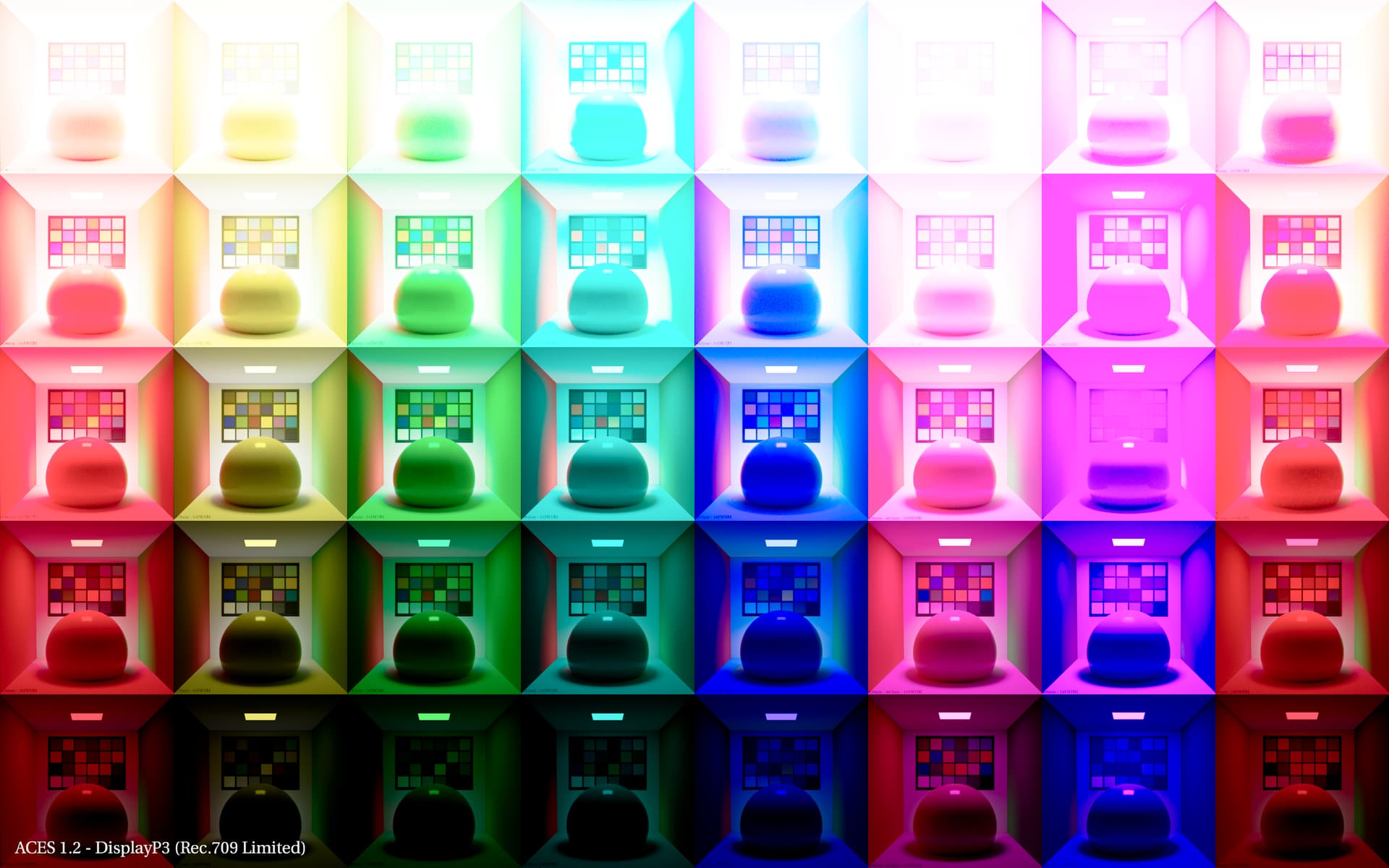
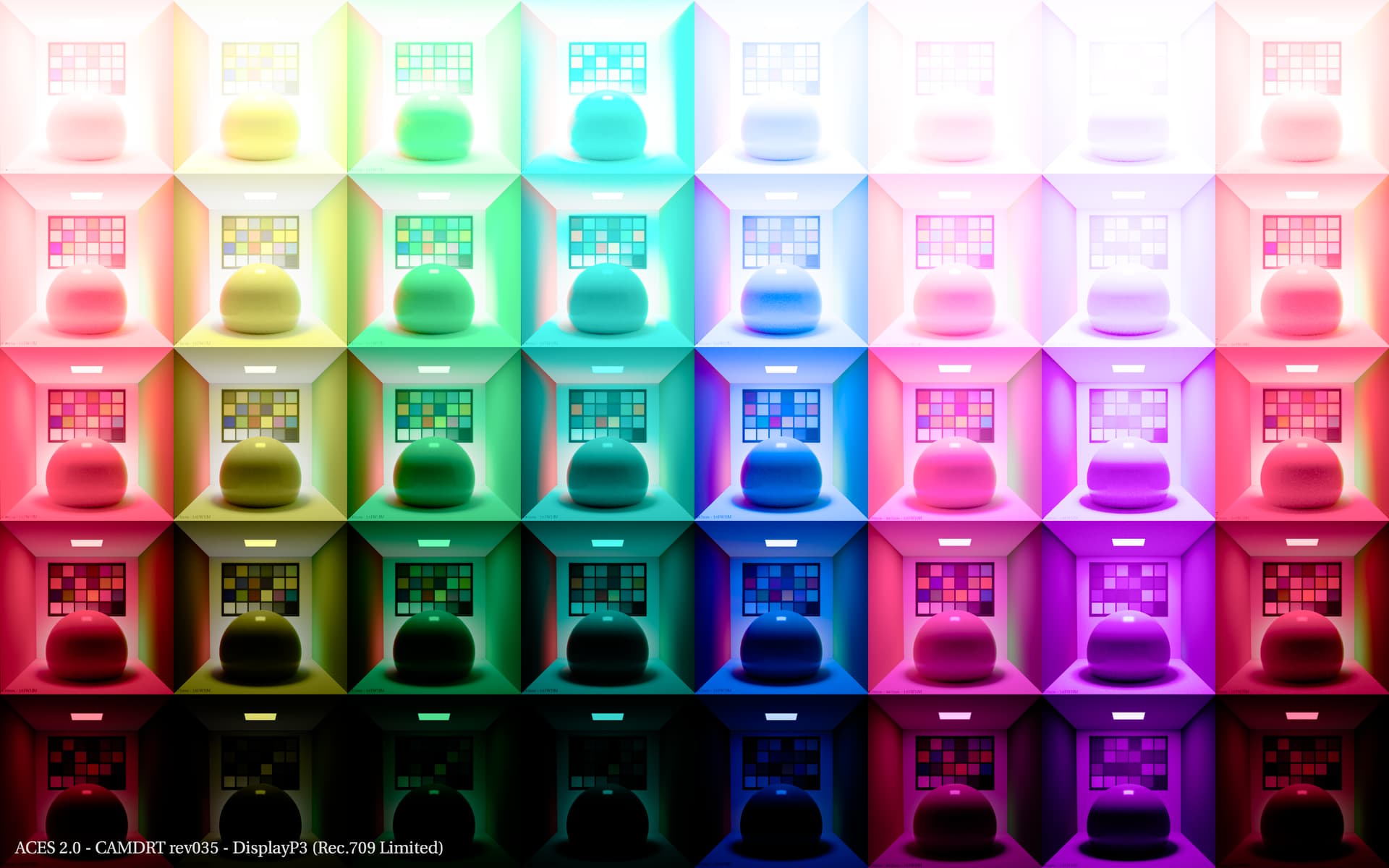
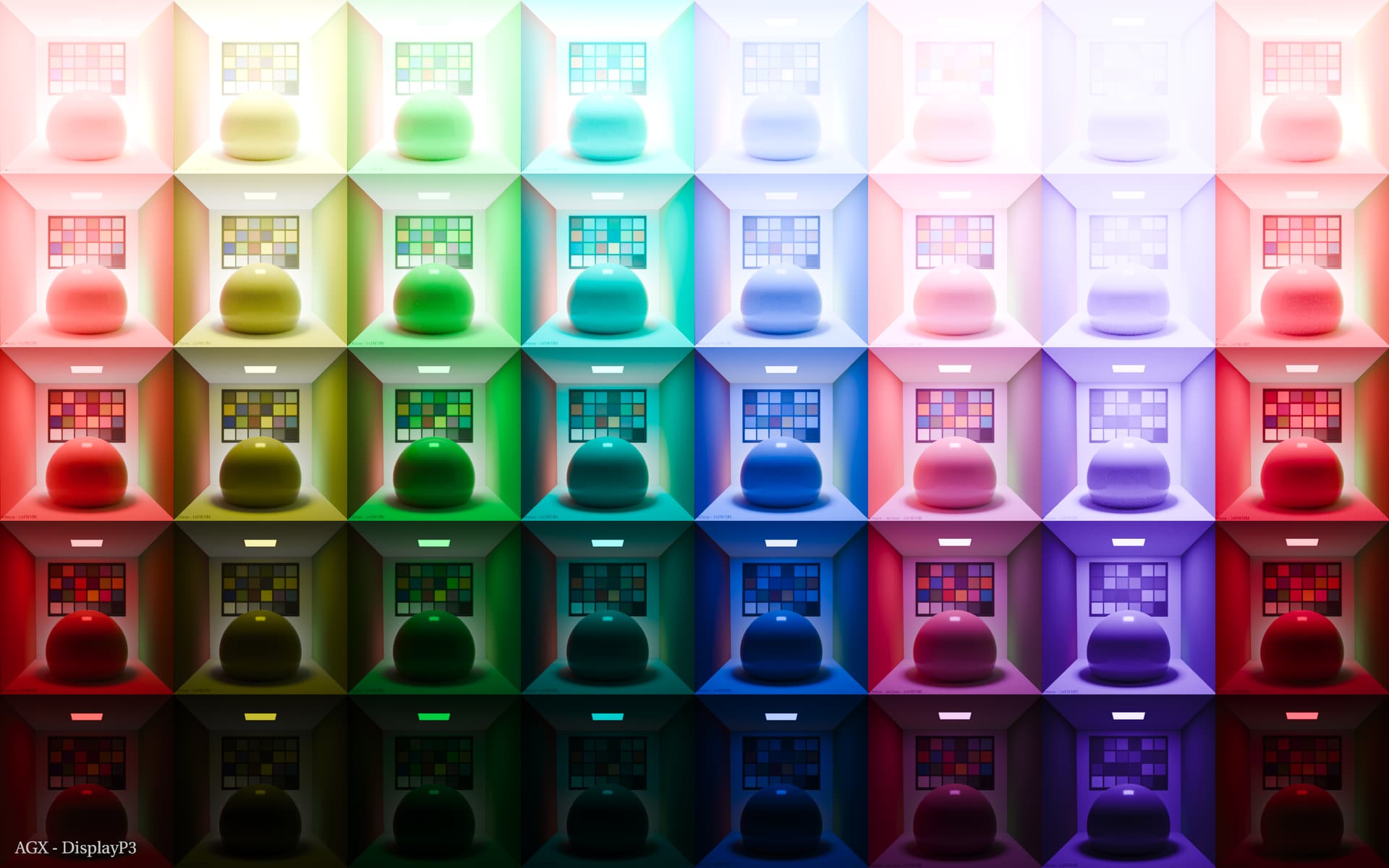
@ChrisBrejon post above got me itching so I “forcibly” found some cycles to create those images that I was meant to do for a long while (I would also like to shoot some skin references against the LED Wall). They are spectrally rendered using Mitsuba 3 using the Standard Human Observer. The 6 first columns are the primaries and secondaries of BT.2020 using gaussian SPDs (10 FWHM), i.e. 630nm, 571nm, 532nm, 493nm, 467nm, 630 + 467nm, the two last columns are 400nm and 700nm, bordering the visible spectrum. The SPDs have been normalised against the luminous flux of a similar gaussian SPD at 555nm but it is obviously not enough for them them to be equally bright. Next step is to render them using a virtual camera to generate physically non-realisable values and maybe address the brightness.
Many things to discuss, maybe tomorrow!
Cheers,
Thomas
Edit: I need to check if the PNG files are properly encoded and I need to write back the EXR file in 32-bit as it clamps.
Hello,
I am already using the new prebaked LUTs of the ACES 2.0 DRT for my YouTube HDR videos. I didn’t like the desaturation in the bright sky. So I started playing around with the Nuke script and the chroma compression settings. In doing so, I realized that chroma compression increases the saturation of certain red colors.
Is this behavior desired? I don’t think so. So I would like to suggest this little fix for the kernel (line 1438):
M *= Mcusp * sat_fact * scaleM;
if (M > JMh.y)
{
    M = JMh.y;
}


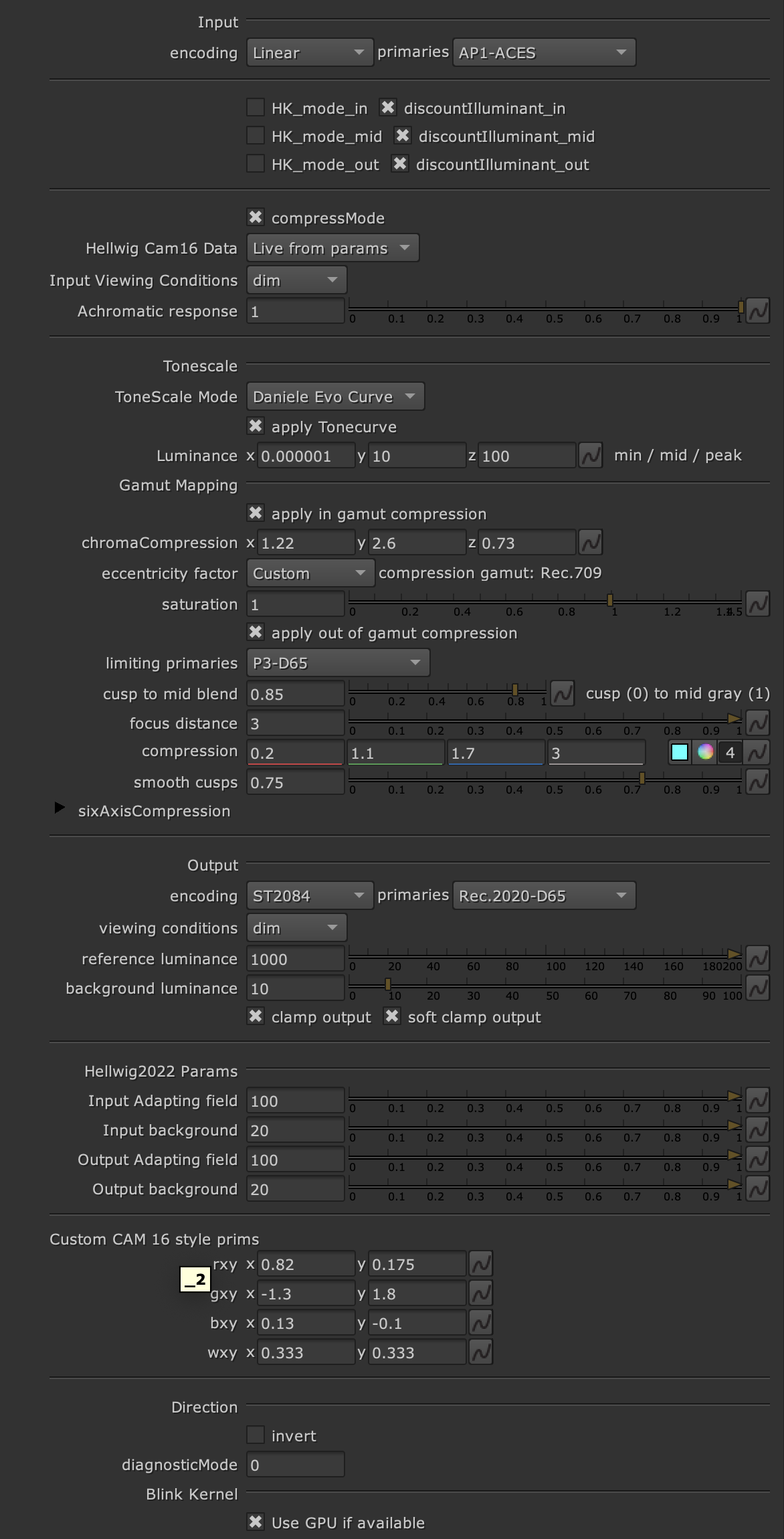

