ACES 2.0 CAM DRT Development

Perhaps. I haven’t given it much thought but implementation wise that would mean one would live as LMT inside the other? There is always the global rendering + ODT that needs to be enabled. If that has some form of compression there are two compressors limiting the possibilities of the first? So the default, no look applied rendering would have to use no compression and look really bad? How would it work when you have to blend the two? Say a logo on top of footage.

I always have trouble fully understanding the inversion requirements. Maybe in some ways this management principle is based on suboptimal approaches and/or software limitations? If you color manage manually you can decide when an output transform is applied and layer stuff on top of it. With that approach you don’t even need an inverse for sake of logos/graphics.

On archival side I also struggle to understand this. Wouldn’t it be practical to archive a master without any overlayed graphics? And full titled master archive as is in the deliverable spaces, rather than an ACES2065-1 version?

Regarding compositing would we really need to have an exact inverse because we need to adapt the source image to the scene we are trying to place that in with compositing tools.

But tbh, I’m too distant from full ACES workflows to understand the benefits/downsides since I haven’t had the need to for any of my projects. For us it’s only grading camera images to Rec.709 and then it leaves the ACES world already.

1 Like

Can’t help but like Daniel’s concept, but I would not call them “looks”… rather two color management schemes.

Also a critical aspect for me is to get consistent management of the various HDR and SDR. Obviously they will differ (as the tone scales do,) but I really appreciate a simple and minimal trim pass between them.

Another possibility with dealing with “extreme” colors can be to treat them as a secondary correction… isolate and fix. Perhaps this is like Shebbe’s “layer stuff on top”.

(not a professional grader myself, but wishing to get the best print (display) from my work)

Also Satrio’s video will not load/run for me - just spinning circle.

(Sorry if I totally misunderstood what you mean)

I used to color grade mostly commercials during the last few years. And if there is a screen replacement of a filmed smartphone / TV - half of the time the added footage comes not as camera source files, but already graded display referred video provided by a phone / TV brand. And it not always should behave like it was really there on set and to receive the same amounts of lens flare, atmosphere fog and other artifacts. On the last project, I keyframed color grading of the composed screen according to a night club stroboscope lighting. But not in a very realistic way, otherwise it would look too dark and flat (realism rarely looks good in a commercial). So I tried to find a balance between the realism and a good looking black level of a smartphone in the frame. Or sometimes it has not to have the look of the surrounding shot scene. Or any other weird case.
And sometimes VFX guys do the chromakey after color grading, right on top of the display referred graded image. While it is completely wrong from a pipeline point of view, sometimes it’s more cost-effective for the client.
So there are all kinds of strange and “wrong” ways of using the tools. And while I agree that using DRT inverse is strange and kind of a bad thing, it still seems to be required. Too much different and weird things happening when it’s not a movie, but a quick commercial with remote post production with workers from different cities or sometimes countries. So it’s better to have a lot of various tools, including the inverse.

I presume then that you are using OCIO and therefore the LUT baked version. The distortions you are seeing may due to the LUTs. I cannot replicate anything like that in Nuke using the Blink.

Again the Blink in Nuke does not produce the same level of bumpiness.

Surely that’s the point. You are free to use whatever adjustments you want prior to the DRT. As well as creative grades you can apply technical corrections such as gamut compression. And you can control it as needed, rather than it being a fixed part of the DRT.

The gamut compression in the DRT is at the output, and is intended to compress to the different target gamuts, so is not the same as a global gamut compression you might apply on the input.

I’m aware that these ‘wrong’ approaches like keying/compositing on graded footage happens. We’ve had these situations too for some of our projects. But I’m not fully confident that it makes it a reason for ACES to amend to such practices when at the same time it wants to be a pleasing DRT to use for grading? But that’s my view based on what I see. Could be proven totally wrong here.

I must admit that some human error has slipped in. While double checking against the exported .exr in resolve I must’ve copied the ACESTransform node rather than the DCTL version of v055 which showed the same. Apologies for this confusion, I checked again and this is indeed smooth!

The green curve is still trending down first before going up however. Not sure if that makes sense in the rendering because blue becomes more pure the less pure it becomes in ACEScg values, before further desaturating through remainder of the gradient.

I would also still hope there could be improvements in the DRT where compression creates hard transitions between compressed (out of gamut) and non compressed values when they transition in that blue area.

I was on the fence about sharing these tests I have been doing, but I was told it could help.

These sweeps are inspired but not equal to MacAdams Moments, this sweep has the same “moment” all around, the x axis is chromaticity angle/“hue”, and the Y axis are log2 steps.


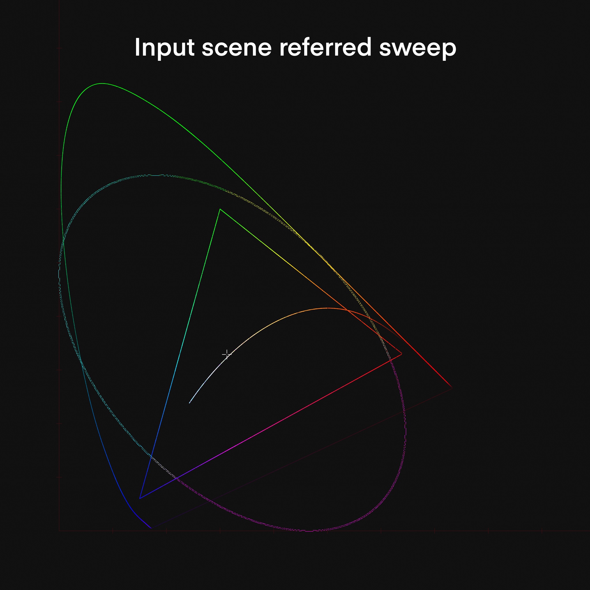
Fig1 xyY view of sweep


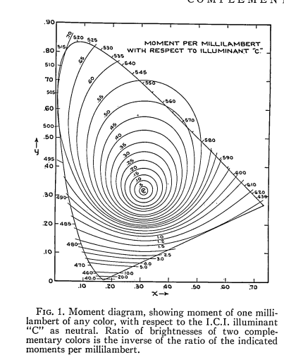
Fig2 MacAdams Diagram

I would say this mainly tests attenuation/path-to-white.

My test was on the assumption that a smooth gradient should be kept as smooth as possible when formed into an image. The sweep is outside the spectral locus but I believe that it shouldn’t matter, and it should be possible to map smoothly enough inside any display space.

I tested Reveal , the latest ACES 2.0 DCTL and my own picture formation.


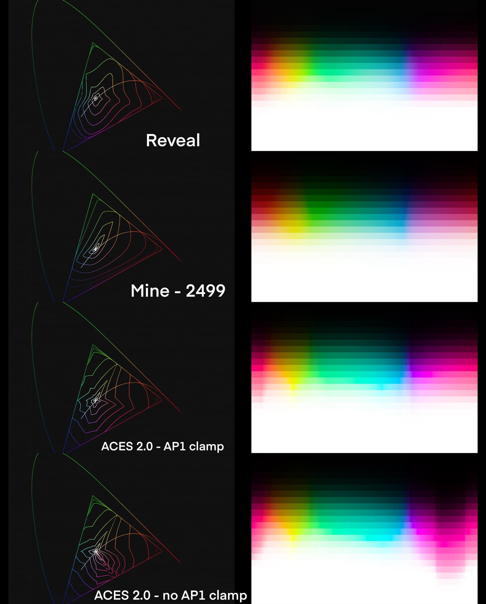
Fig 3 . comparison of DRTs

As you can see, Arri’s can smoothly map everything well enough, even when many values are well outside LOGC4 , even if I it’s a LUT so its not the most accurate

ACES 2 seems to struggle, it creates very pointy flower shape. The largest discontinuity seems to be around the blue and red chromaticities ,which interesting enough are well inside rec709 before picture formation, and the AP1 clamp seems to be necessary for the “magenta” values , but it also breaks the things in other ways. I believe this behavior is mainly from the “Chroma Compression” step when it tries to bring everything inside rec709.

I have no idea how useful this is, I can only say that it’s possible to smoothly enough “map” the camara data, even if they are “non-sense” in terms of human vision.

Hope it helps in some way.

XYZd65ramp.nk (48.9 KB)

XYZd65 Ramp nk group

8 Likes

Thanks! I think comparisons to other DRTs are important. People for sure will compare it, so it’s better to do it before the release.
For me the 2 most important things are smoothness and reaching the corners, in this order.
It’s way more important than not collapsing to notorious 6 or HDR SDR visual match or even perfect invertibility.

Also, just tried JP-2499_DRT and I like how it’s handling the saturated colors in the shadows, thanks for sharing!

When seeing the last replies, I had a similar albeit simpler idea of using concentric circles around the whitepoint, (derived from the radial grid without the spokes), I used to show how the CAM model is distorting the space a few months ago. I found that visualisation quite useful but did not have the time, so thanks for doing that, especially the comparison with the other DRT, this is awesome.

I think it is beyond useful and a design requirement: a non smooth mapping producing a kink in one space will likely exhibit a kink in another one, unless being extremely lucky and that the space transformation happens to undo the kink.

Often, working in a space, doing processing and transforming out to another one will produce significant gradient changes and it is fine provided those changes are smooth. However, this should not introduce harsh discontinuities along the way or there will likely be visual artefacts.

I believe the shape happens due to the hue dependent nature of the chroma compression, that different hues are compressed different amount and that the compression reduces further out the values are from the achromatic (and also the fact the compression space is normalized with the AP1 cusp M). If it was just a constant compression for all hues (around that circle) it would be smoother. Here’s a quick test with a constant compression in v055:

(Note that this example is interpreting the input as AP1, not AP0, so the AP1 clamp is not affecting anything. The AP1 clamp will introduce sharp transitions (and create the “pointy flower” shape) always regardless of the compression being hue-dependent or not, when the input is outside AP1.)

That won’t invert to AP1. But here’s another test that still has hue-dependent compression limit but the compression space normalization is constant and should in theory invert to back to AP1:

This was the above input to the chroma compression (interpreted as AP1), after the tonescale and chroma compression rescaling steps:

And this is what it would have been if it was interpreted as AP0, due to the clamp:

(edit: ignore the “gap” in the circles above, it’s an issue with this particular chromaticity diagram output, it’s not in the actual input.)

2 Likes

Not directly related to the discussion above, but I have been investigating the noticeable blue band in a colour wheel using a 3D JMh plot.

This is a crossfade between the source ACEScg colour wheel and the DRT output plotted in JMh. It would appear that the blue band comes from the way the corner of the hexagonal plane of the source is “folded in” by the gamut compression. The fold does look rather sharp, and I wondered if that was related to the use of threshold = 1 / limit in the gamut compression. However it would appear that it is related to the proximity of the AP1 reach boundary and the limiting gamut boundary around blue. Non reach compression produces a much smoother fold, and “diffuses” the blue band.

Non reach compression means it is not possible to hit that blue primary with a source inside AP1. So this seems undesirable to bake into the DRT. But it does suggest that a JMh based LMT which used a simpler M compression could smooth the output, at the expense of not being able to hit the primaries. Arguably this kind of LMT is built into other renderings, which don’t have the constraint of having to be able to fill the display cube (I don’t think any of the popular ones do) which makes it far easier for them to produce a smoother looking rendering “out of the box”. We could even have this LMT enabled by default, and it need only be switched off by people who needed to hit those corners.

2 Likes

Since you are about to deliver this luminance mapper, an LMT seems like the reasonable thing to do.

Nonetheless, I find it very stimulating to see how very different answers have been given to a similar problem.

On one hand, we have Color Management Workflows which indeed deliberately let some values escape the display gamut in their DRT. And rely on looks/LMTs to handle those.

On the other hand, we have “others” explaining that it does not matter to reach out the primaries nor to invert because it is a protocol issue. I have looked recently at the AgX OCIO Config and I hadn´t realized that the available looks are actually applied on “image linear” state… Quite interesting.

I understand that this would be a change for the industry but one could argue that an improvement of protocol would have removed two of the constraints this group has been struggling with. Maybe looking at the protocol (this is an Architecture VWG, right?) would have helped.

In the end, it all comes down to the strategy/vision I guess.

Chris

2 Likes

They are also “folded down” which produces a reduction in luminance and possibly exacerbates the problem. Is it because the cusp is too low? I haven’t looked at the code in ages but do we have any control over it?

The achromatic response slider in the GUI would be one way to change that. It changes the R,G,B weights in the model.

I have been experimenting with an LMT to mitigate the effect of the blue band in an ACEScg colour wheel. Here it is if anybody else wants to try it. It is just a hue qualified M compression, so it converts the input to JMh, compresses M and converts back to RGB.

It makes it impossible to hit the blue primary of the display. But if the blue artefact we are seeing is an inevitable consequence of being able to go right into that blue corner, then an LMT like this is an option for people who are happy to sacrifice that full blue for a smoother rendering.

1 Like

I think I need the gizmo called “grad”? Or could you unpack the gizmo into a group and post the script again?

I don’t see a gizmo on Nukepedia called simply “Grad”.

Sorry, you are quite right. I forgot I had use one of my own custom gizmos in my experiment.

I have replaced that now and pushed an updated version.

1 Like

“But” is doing a lot of work here.

The “artefact” is a byproduct of the rates of change the gradient fields are embedded within.

Did anyone try the “transparent” tests yet? I suspect not, as I believe they will showcase the above point precisely in a very tangible manner.

1 Like

Isn’t it far from the perfect situation, when an LMT is needed just to make DRT to be smooth so it would be somewhat closer to other DRTs in terms of smoothness?

I mean, why would one want to use ACES 2 DRT at all? The most common display device is SDR and most common delivery is SDR only. So the SDR HDR visual match is not a requirement for the most common cases. But even when SDR HDR visual match is needed, there are other options that while far from being perfect in SDR HDR match, still way better in the the most important thing - smoothness.

I’m really surprised, how something can be more important than that. Any other thing can be fixed by an artist except for the smoothness of a DRT.

To be completely honest, I have a feeling that the current implementation still isn’t discarded, only because of how much time already have been spent on it.

If having all the requirements at the same time is impossible, why sacrifice the most important one?

2 Likes

The blue star on yellow before and after the fix as two plots. Yes, the “gradient band” inside the star is nearly gone, but the kink in the blue is still there and the maximum values in the center of the star are a slight cyan and not blue.


ACES 2.0 rev055

ACES 2.0 rev055 - JMh blue compress from Nick

Here is the overview from my last post before and after the fix with a nuke viewer gamma of 0.4 to see the issues more clear.

Left ACES 1.2
Center ACES 2.0 -rev055 without and with the fix
Right ARRI REVEAL.

The blue star improved somehow, but the red star has a similar issue where the center has an inner ring.
Of course the LMT was not meant to try to takle this issue as well.


Just for my understanding, being able to hit the corner is primairily for sake of an inverse? I would guess no one would really care about hitting it in grading if that results to what we currently have?..

How far off is ‘not hitting the corner’? Is there be a world where we could say, we can ‘get away’ with it?

If there really is no way to have smooth rendering and being able to hit the corners I can live with an LMT.

The only thing that is not quite clear to me is how this would be implemented. What if having that LMT enabled becomes so ‘popular’ pretty much everyone not needing/caring about inverse wants it enabled? We’d always have to place/apply it manually which may not be as trivial or even possible in some software utilizing OCIO. I know Blender has a look dropdown but not many other CG/Composite packages do no? And including it as Display Space (LMT+ODT) within the config, giving it an extra option in that list sounds a bit unelegant.

But maybe I’m already running too far ahead with this.