I have been thinking a bit about this thread and I wanted to share some ideas if that´s okay.
Please take them as a bit of exploration rather than a proper solution.
I think that the OT VWG proved that it is difficult to satisfy everybody when it comes to Output Transforms/Picture Formations. So the idea for ACES 2.0 was to provide a more “neutral” starting point, so everybody could craft more easily their images according to their taste/needs.
But to me this implies an important step in the workflow: the LMTs (or looks by OCIO terminology). And even if it is interesting to compare several Picture Formations “out-of-the-box”, I would argue that it does not tell the full story.
So, having that in mind, I decided to develop a look for ACES 2.0 and I will share here the results.
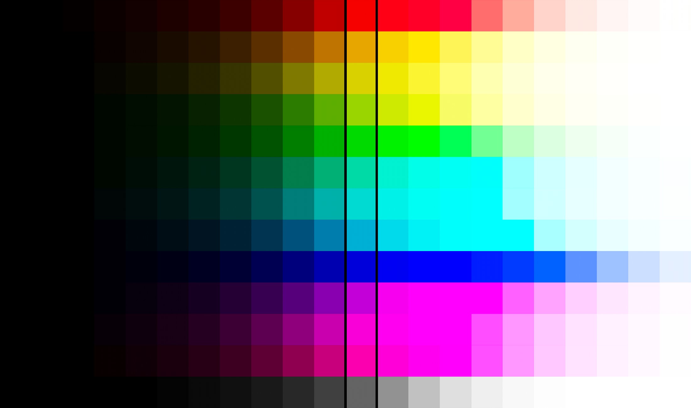
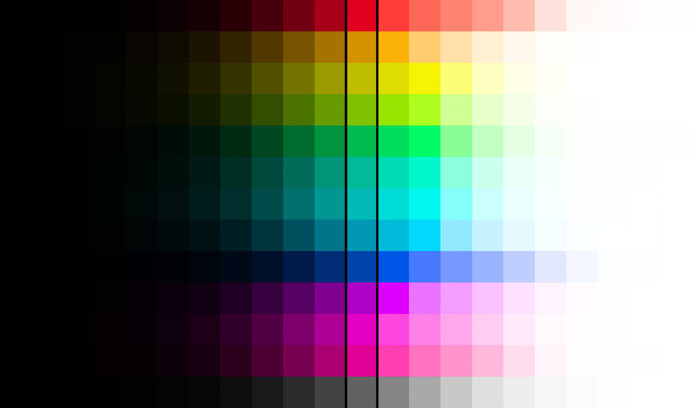
My first step was to look at an ACEScg sweep where each square represents an increment of one stop.
I am putting here ACES 1.X for comparison:
Most of you have already seen this image with the “infamous” notorious 6.
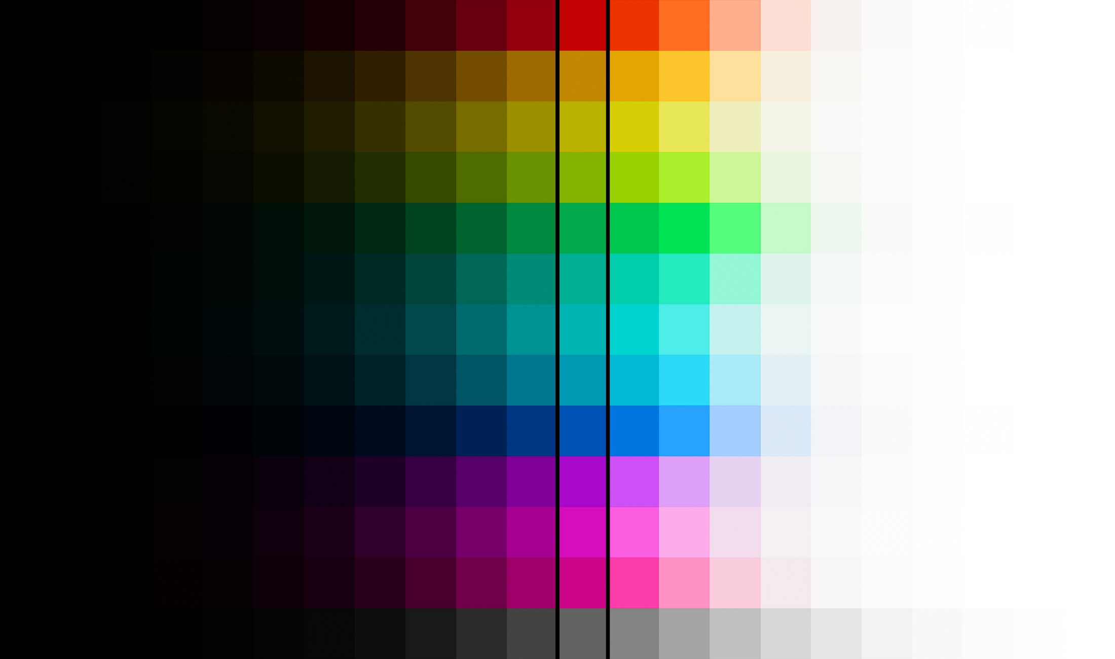
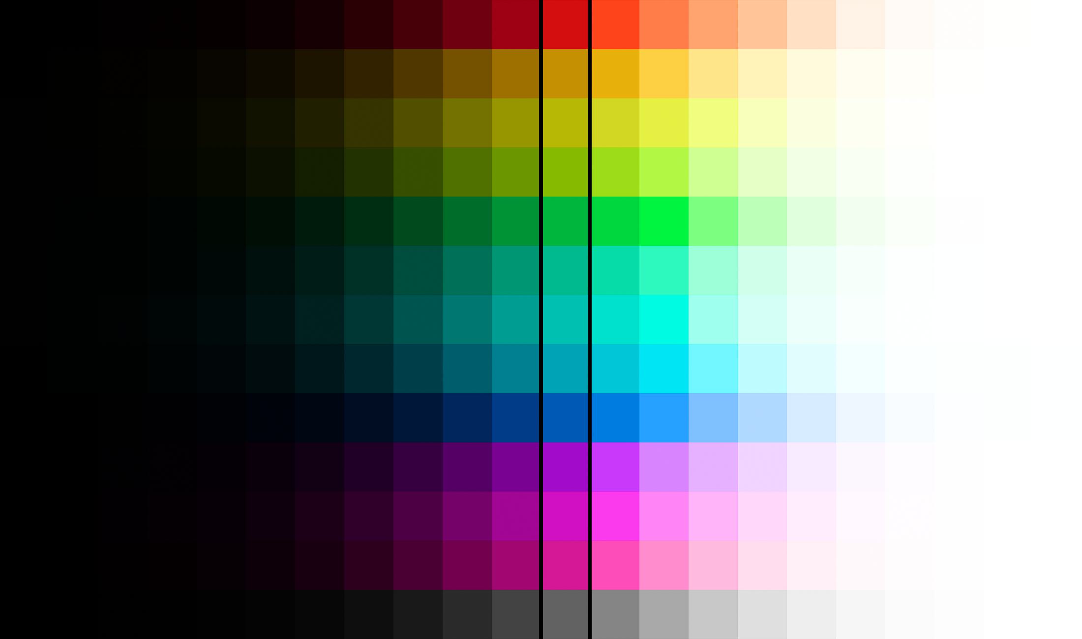
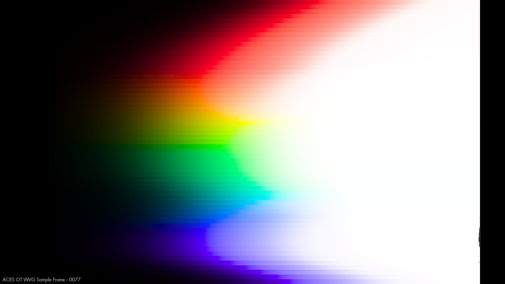
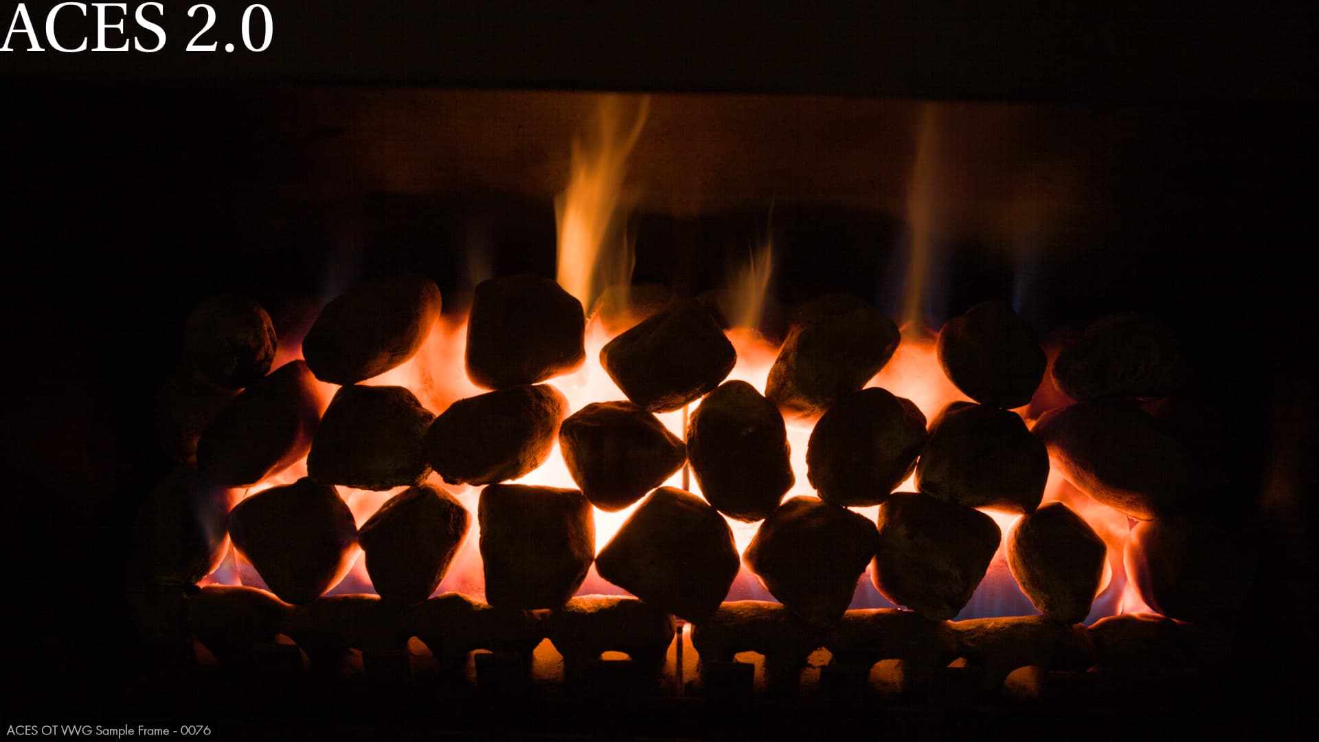
Now here is the same sweep with ACES 2.0:
At first glance, this looks like an improvement since the “notorious 6” are gone. But as always, devil is in the details. Two things jump out to me: the rates of change and the purity (or chroma) compression seem “off”. It is especially noticeable in the yellows and greens, but this might be because of the requirement to “reach out the corners” of the display gamut.
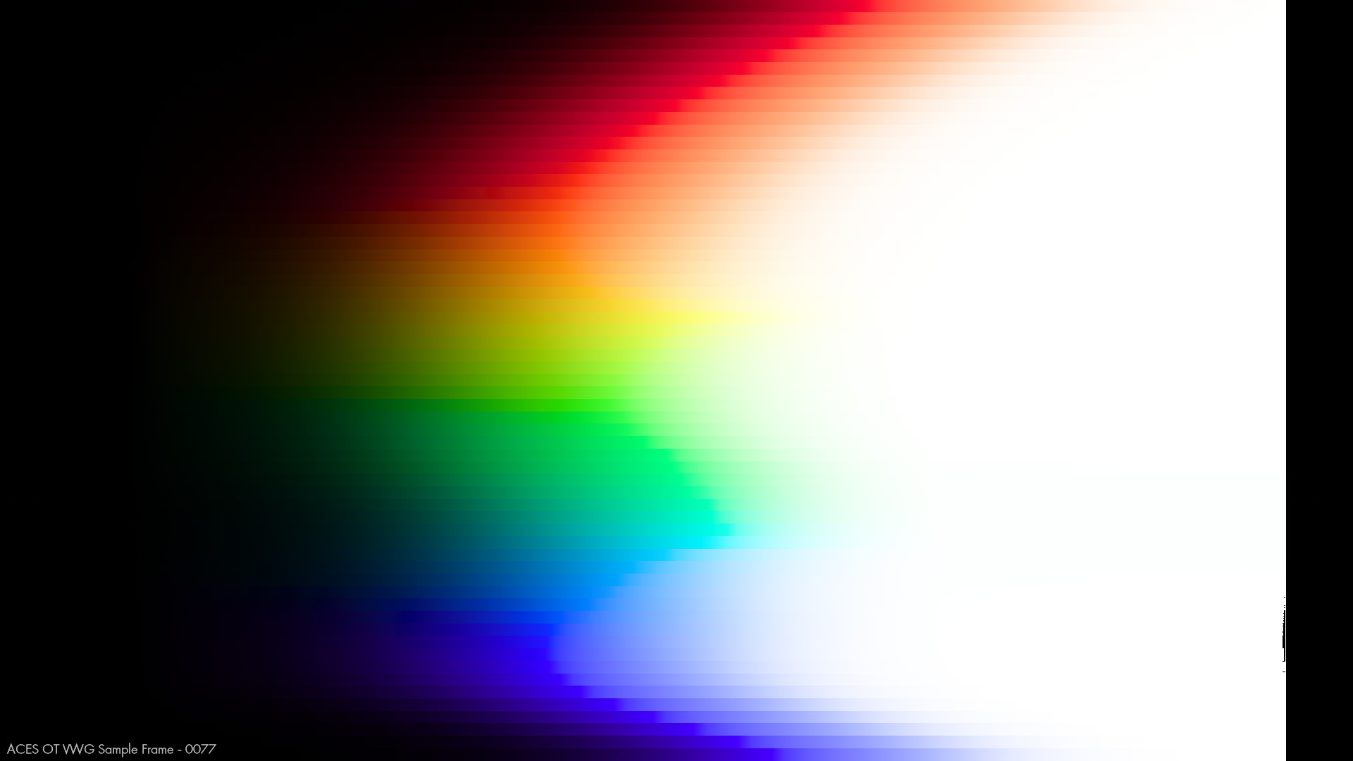
Here is the same sweep with my LMT (“CB-101”):
Again, I don´t think this LMT should be perceived as some kind of solution for anything but more of an attempt to develop a “pleasing/natural” look under the picture formation.
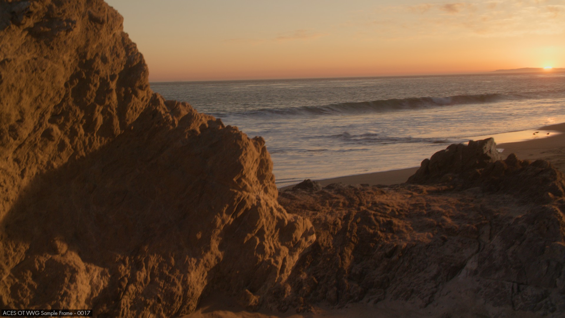
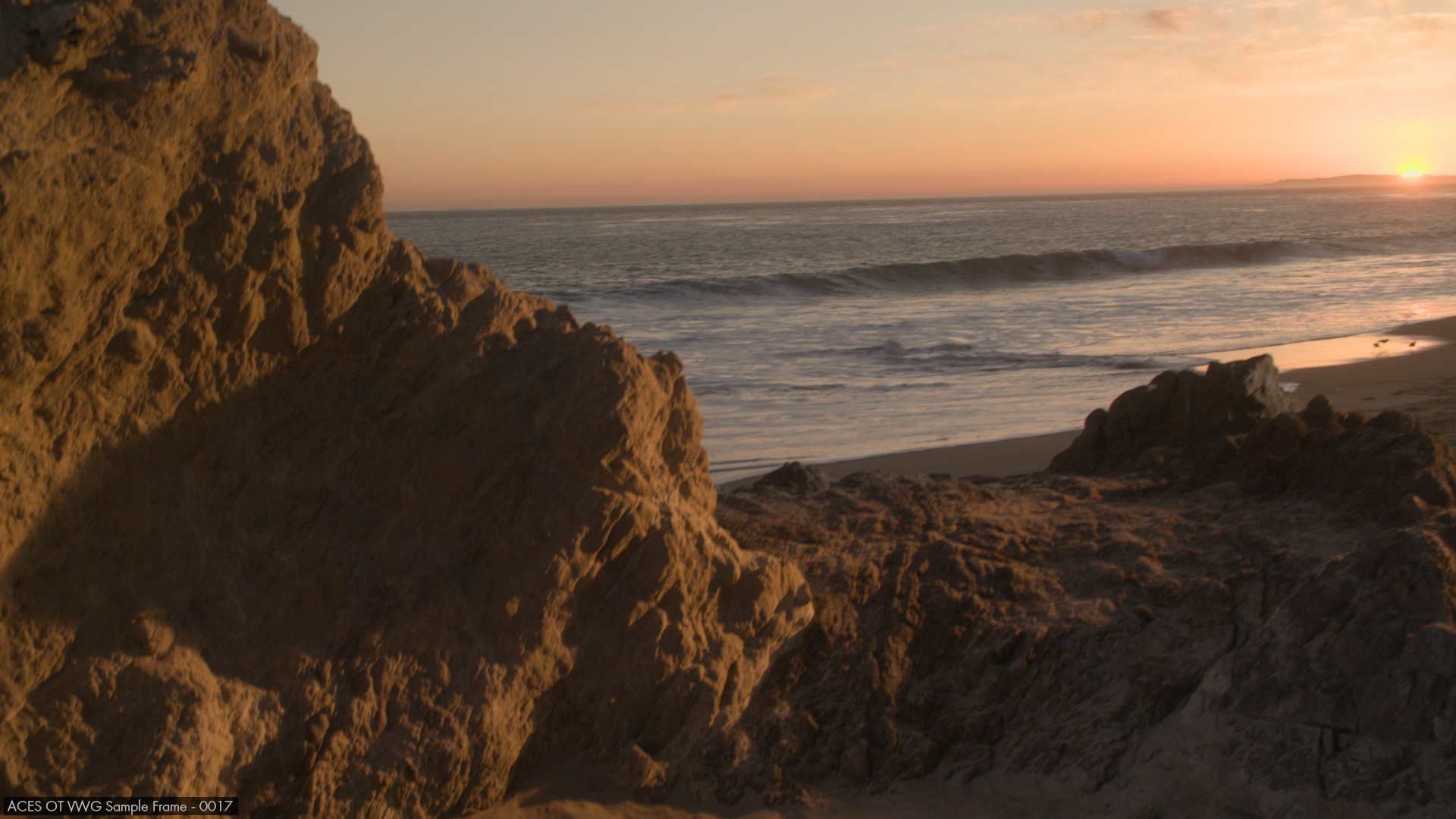
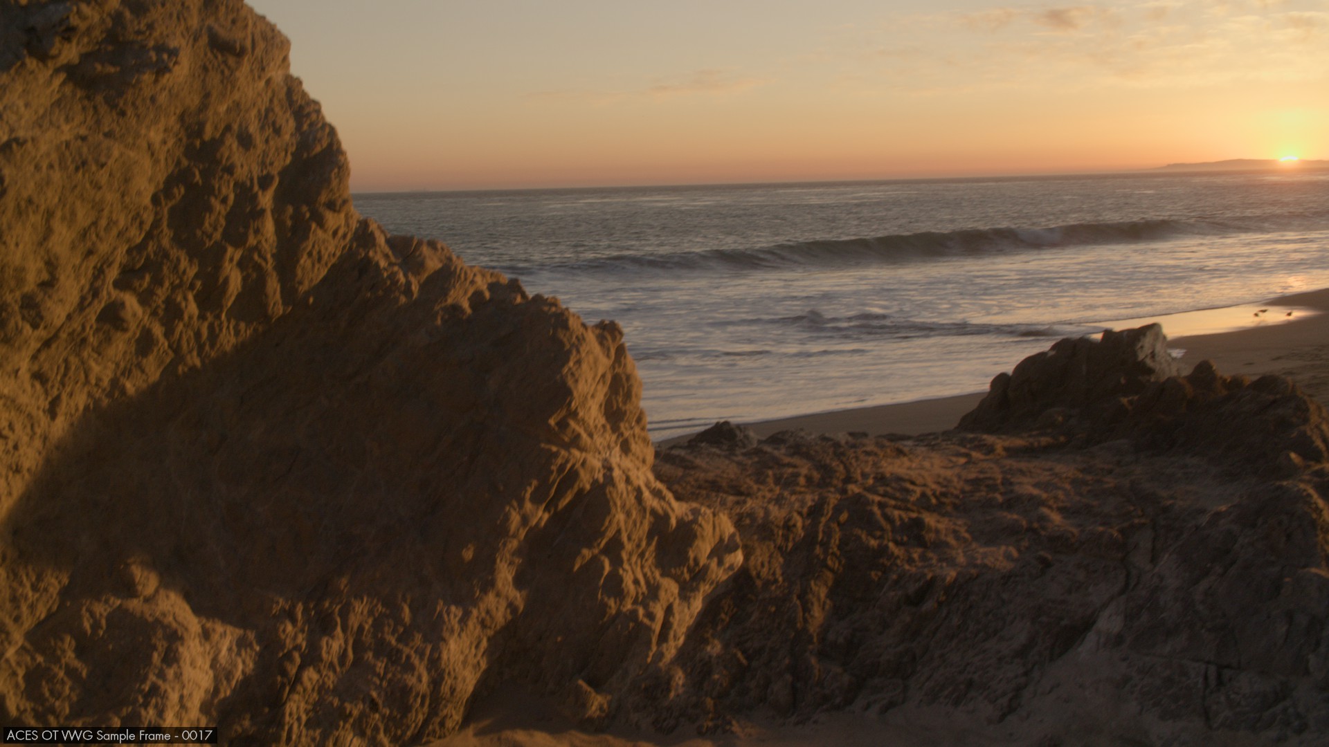
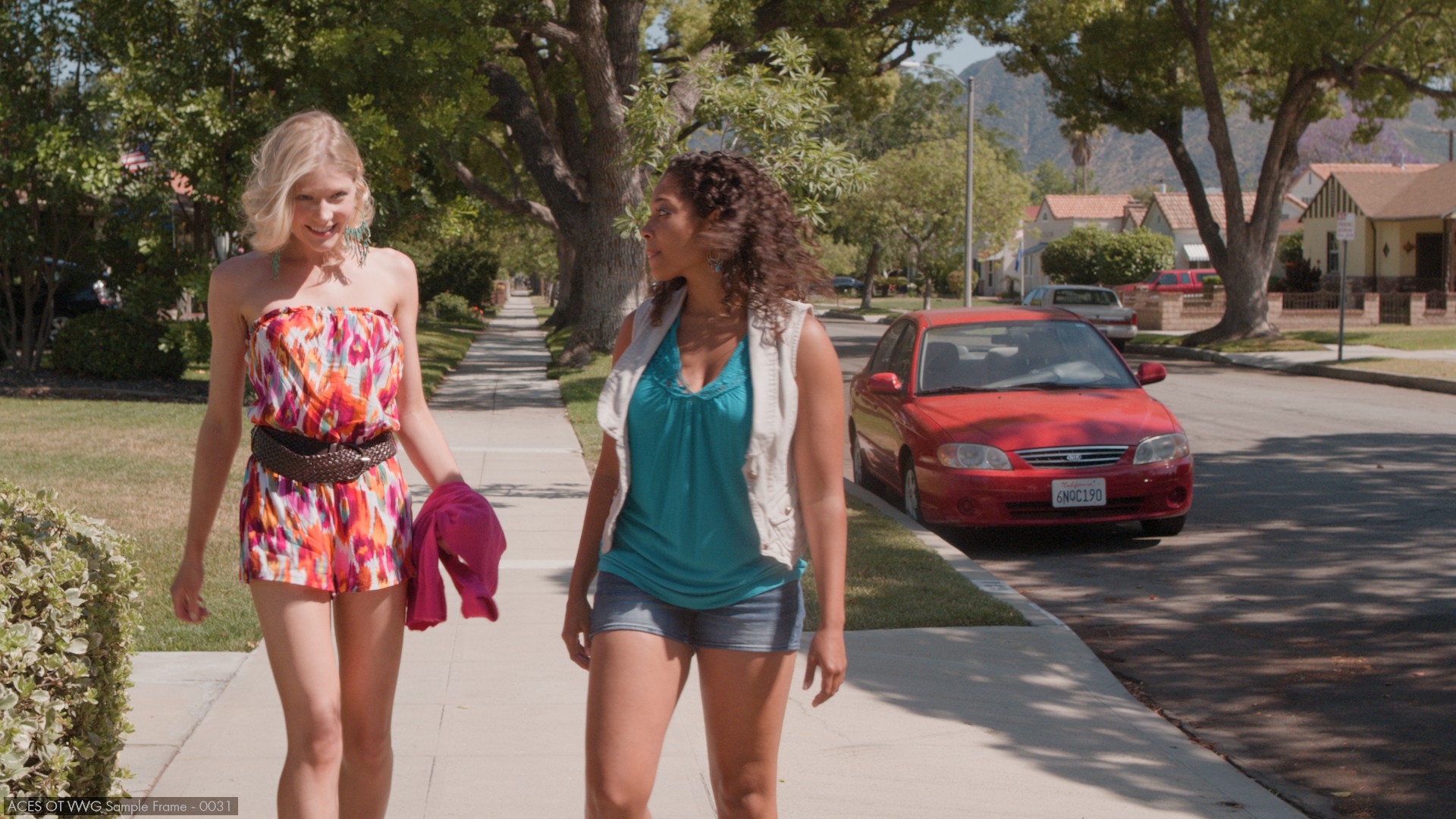
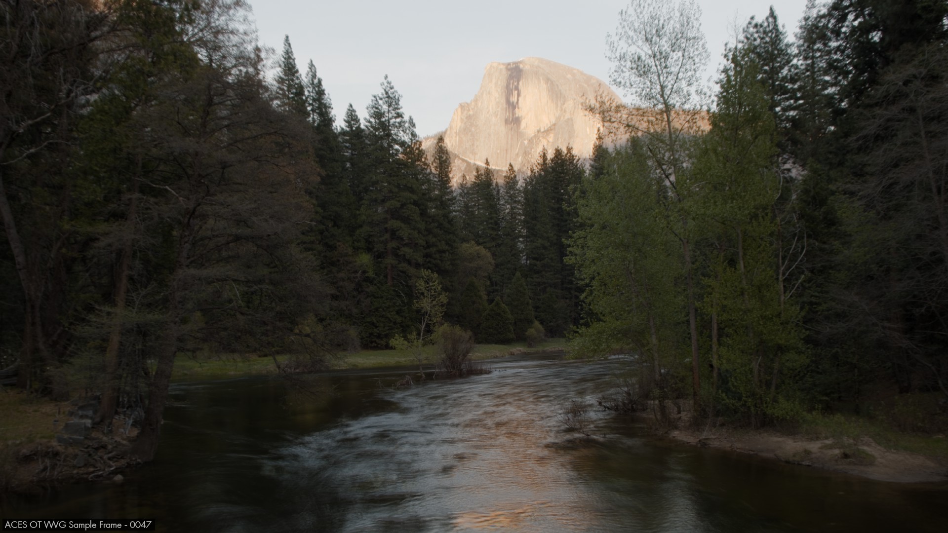
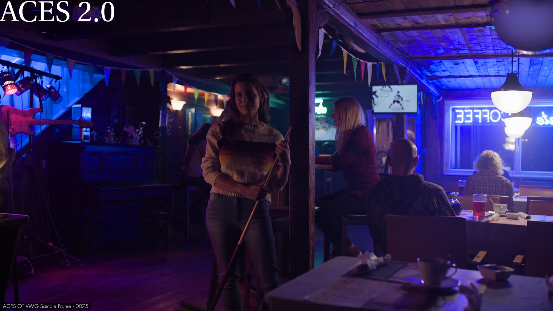
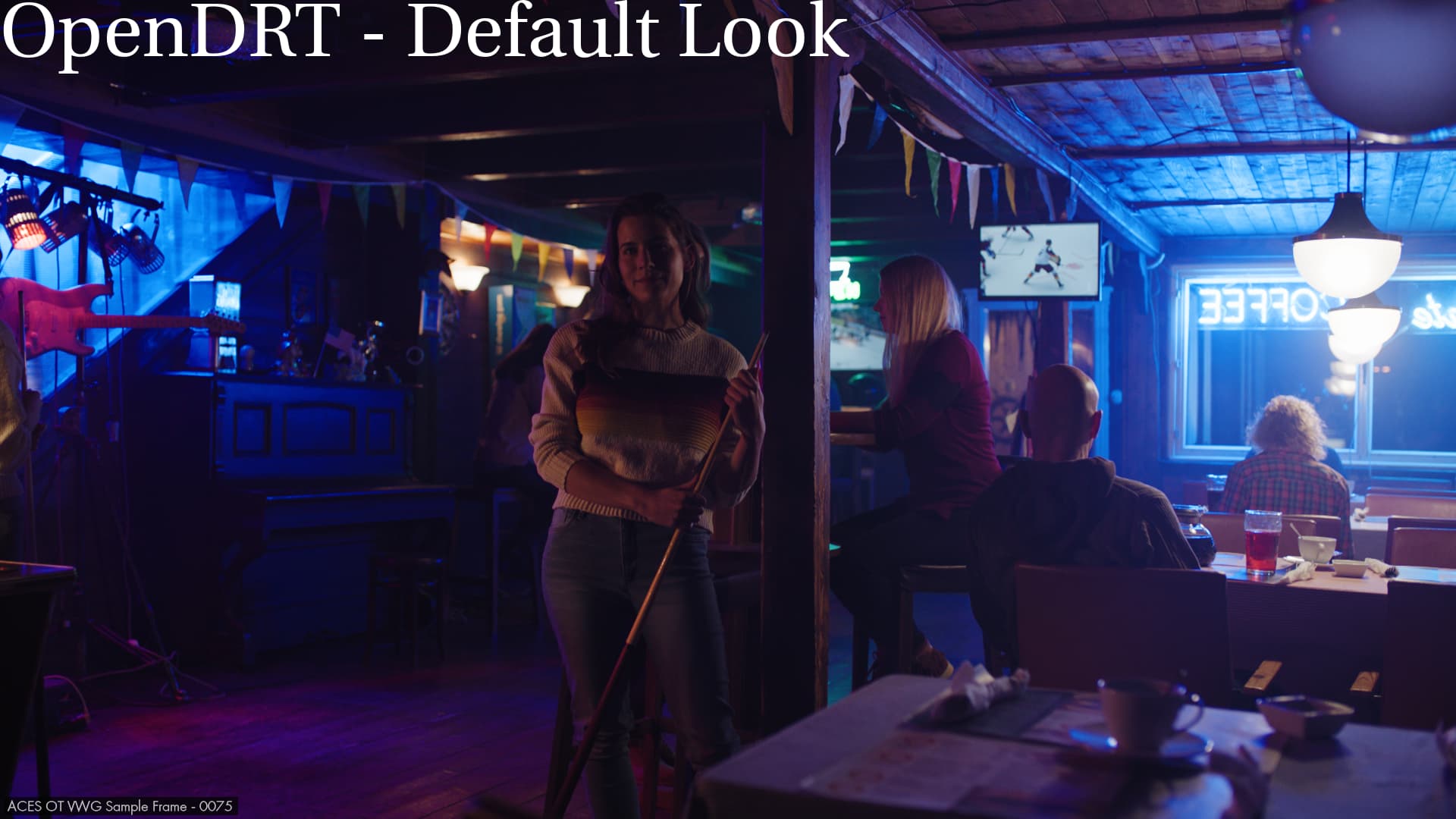
So, if we take our sunset example, here are the results. First ACES 1.X with the high contrast and shift towards yellow:
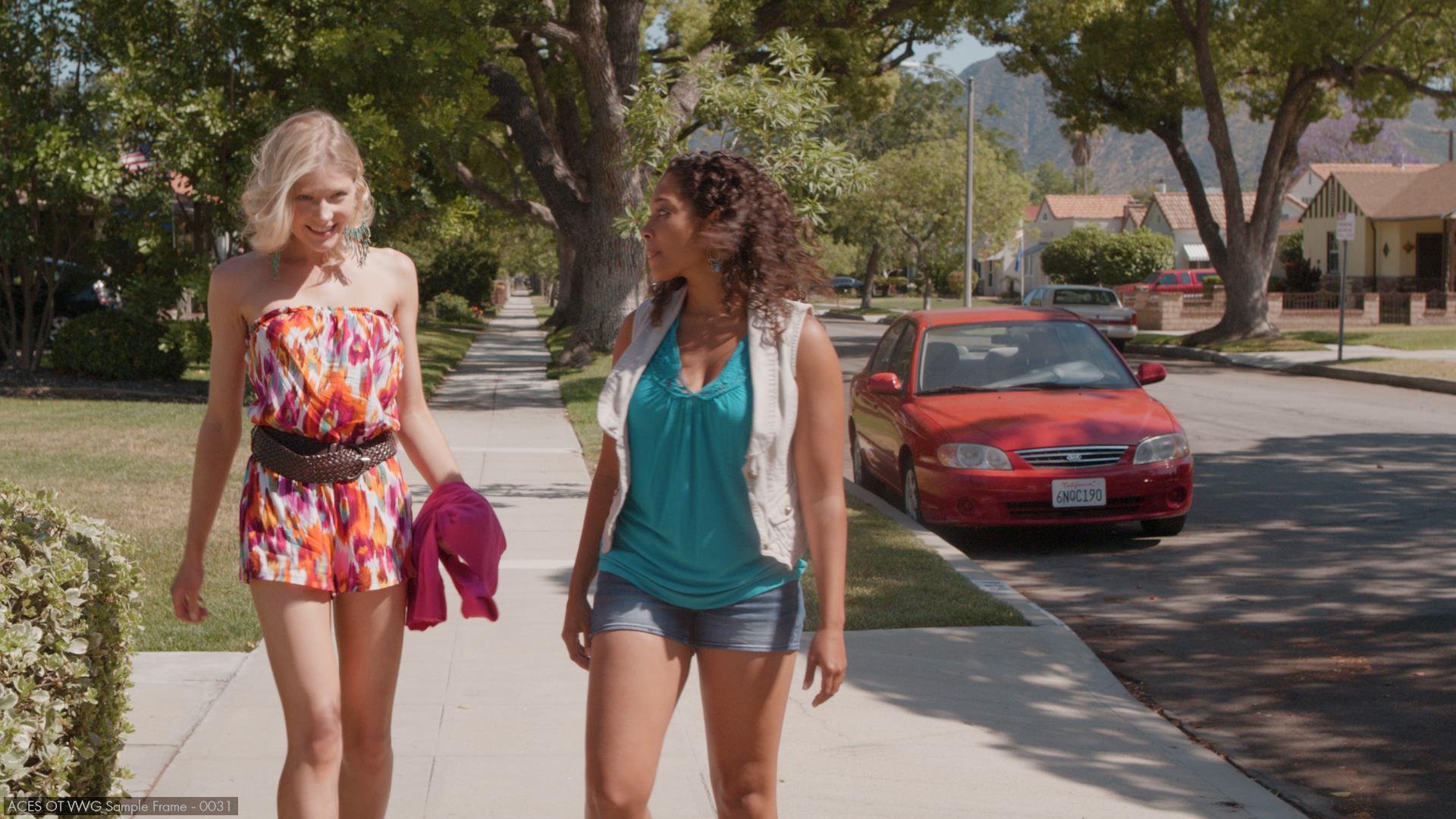
Then ACES 2.0 with no shift towards yellow (in the sky region) but the polarity flip (around the sun):
And finally, ACES 2.0 with my LMT where I ty to fix the polarity flip (I don´t think my attempt is 100% successful) and I reintroduced a slight “hue path bending” to avoid the salmon sky of the previous image:
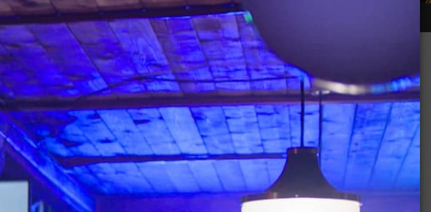
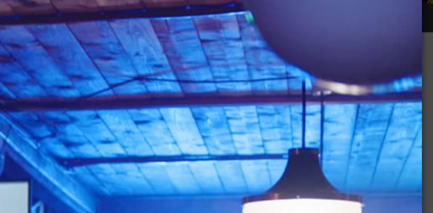
I tested my LMT under a bunch of images and I think it helps in some areas. But I cannot help to think that in some aspects I was fighting the picture formation. For instance, I was not able to fix the blue artefacts shared by Charles in his second example. It would be nice to think of a potential LMT fix for this.
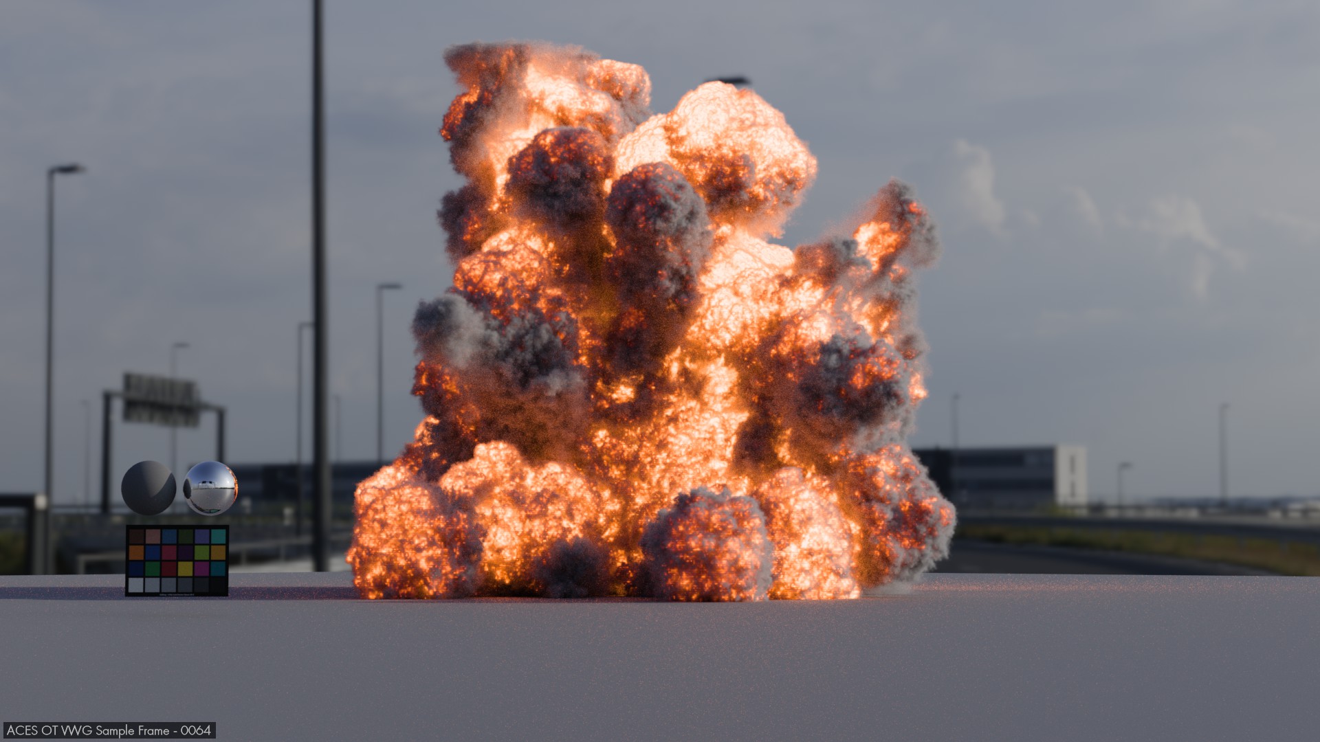
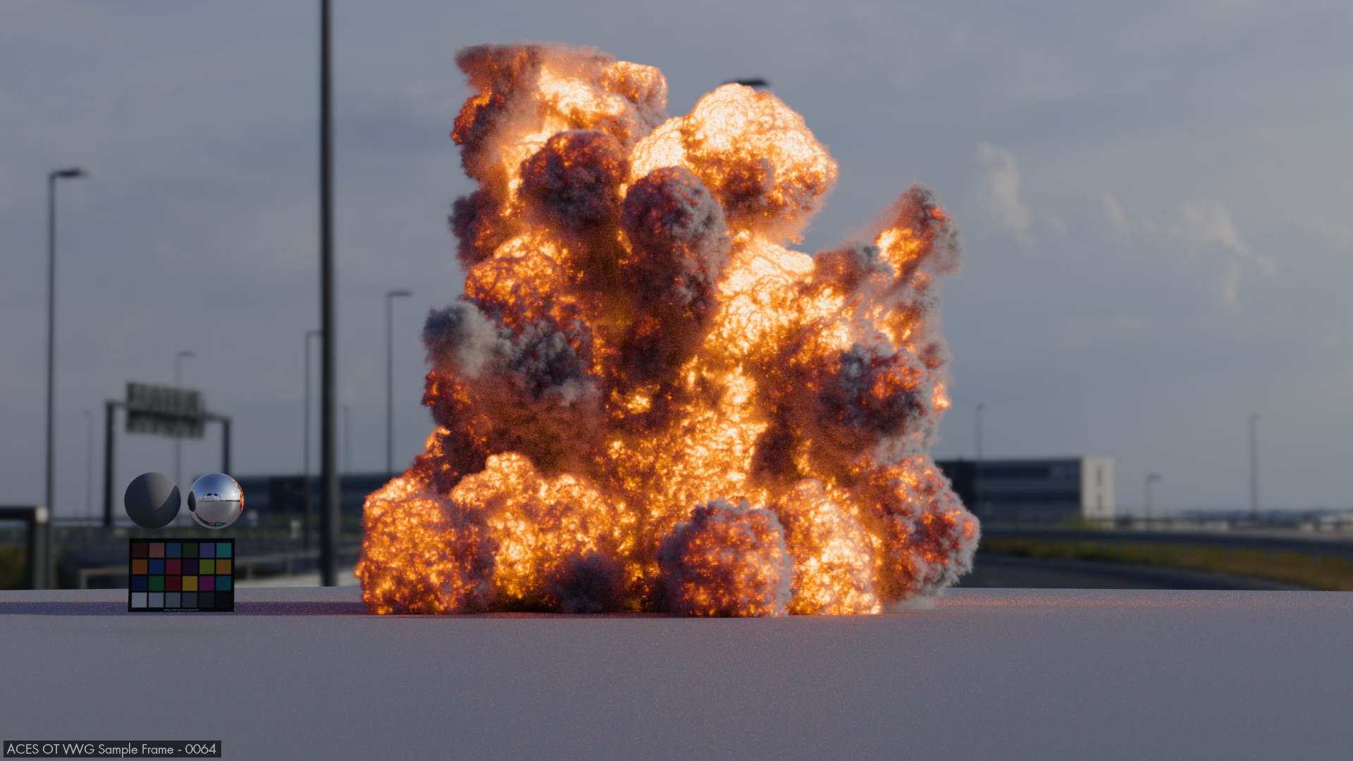
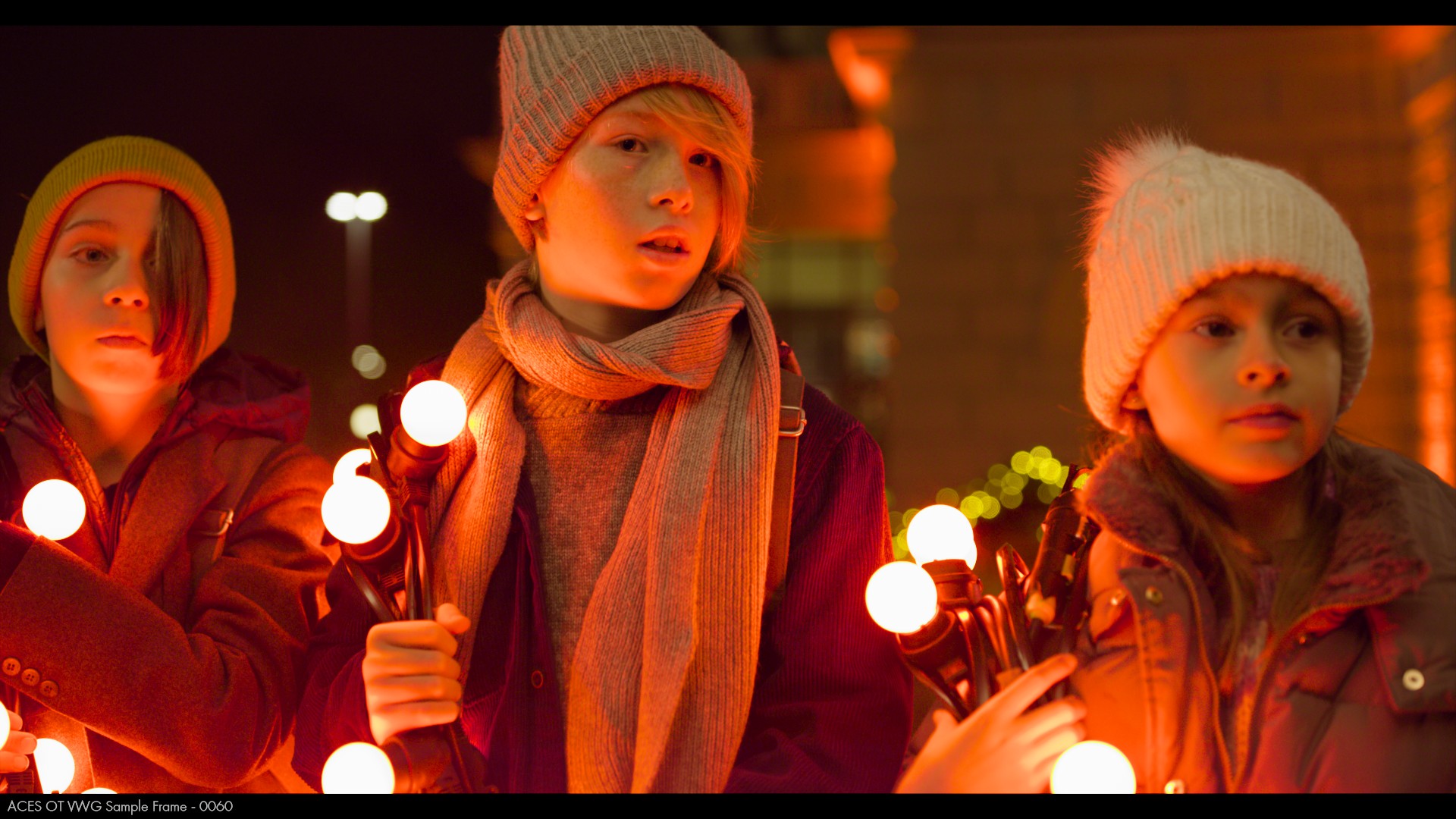
Here are some more examples:
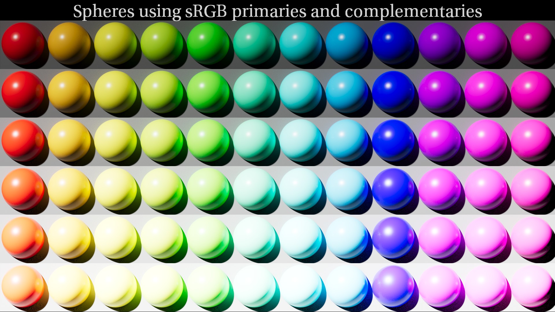
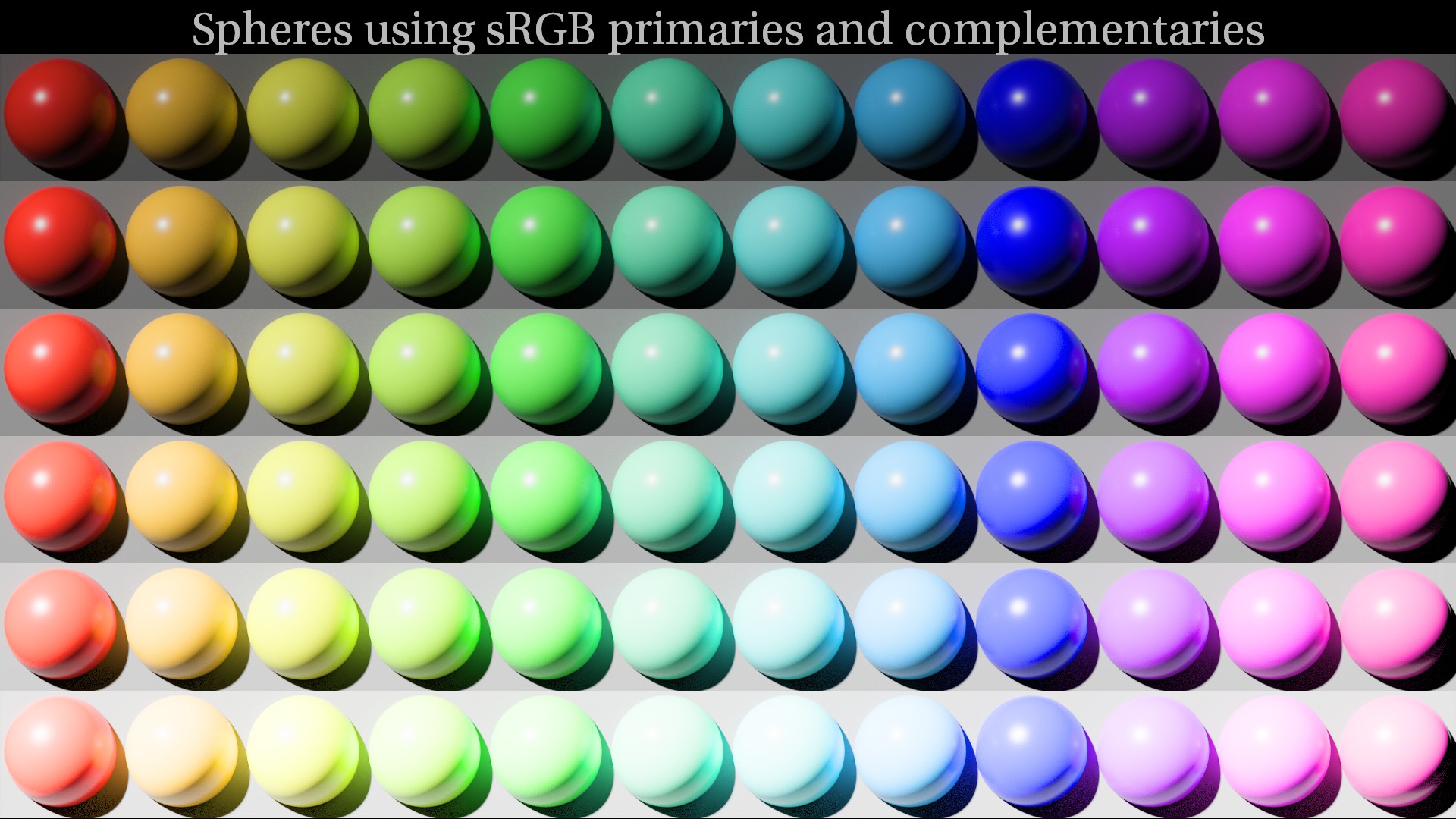
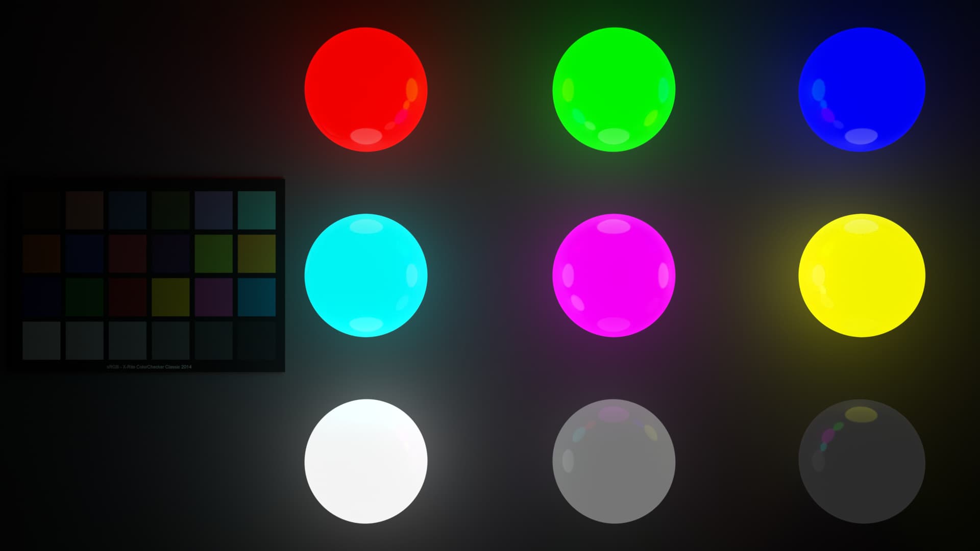
First ACES 1.X with the sRGB spheres and their hue skews:
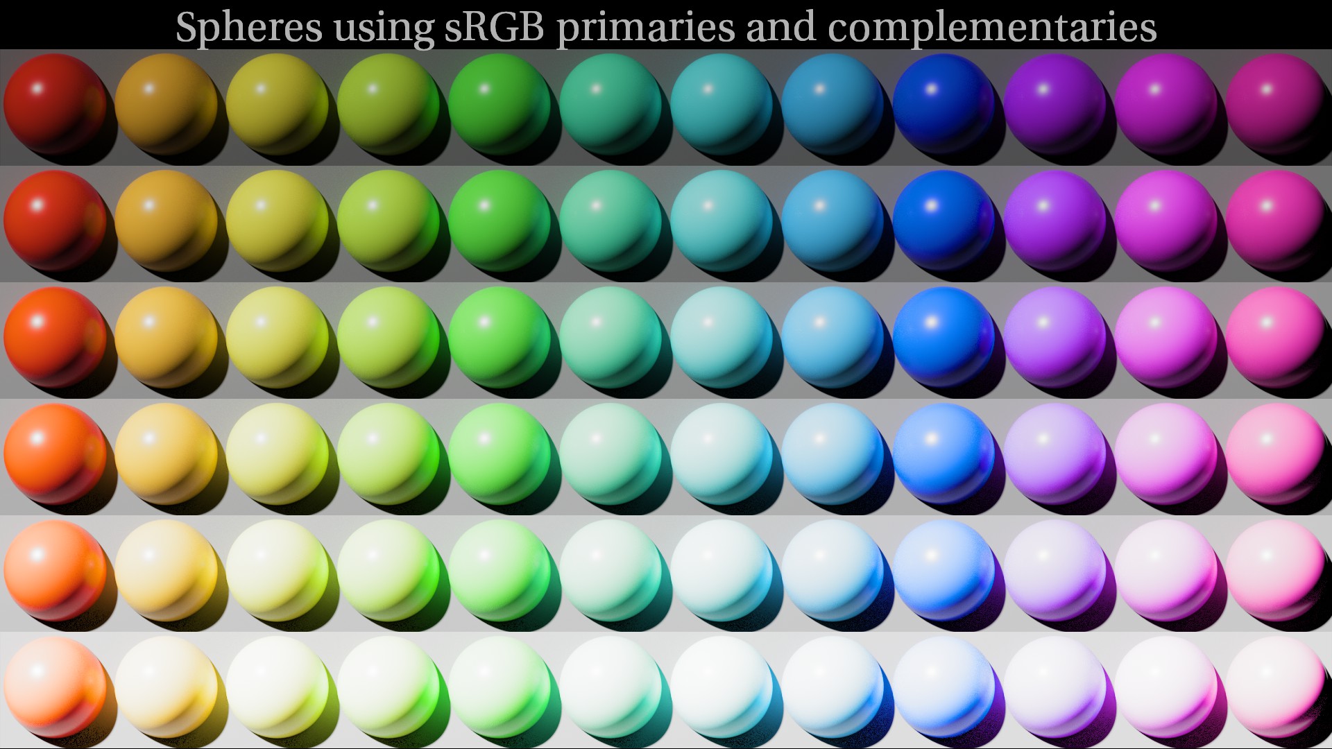
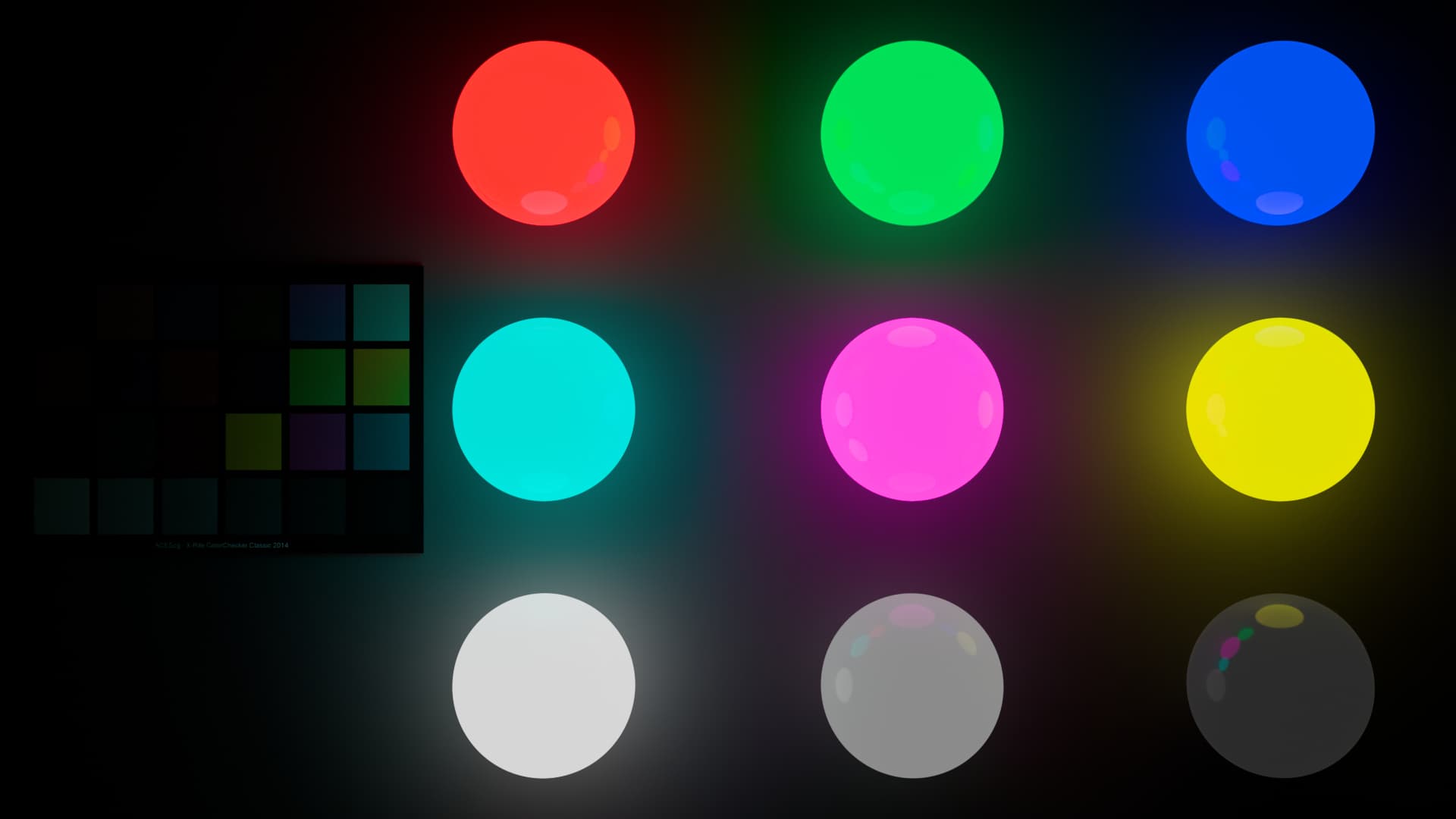
Then ACES 2.0 with the polarity flip (I think that if you pay real attention, you may notice a dark ring around the specular highlights of the spheres):
And then ACES 2.0 with my LMT (which is far from perfect if you look carefully at the purity compression in some areas):
Here are some more examples:
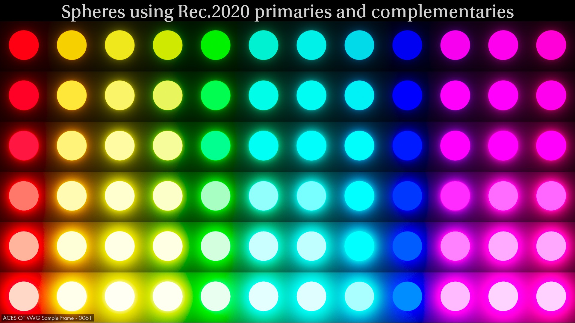
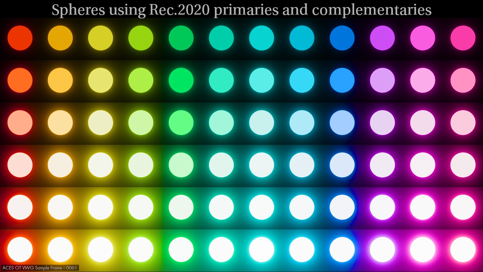
First ACES 1.X with the bt.2020 spheres and the notorious 6:
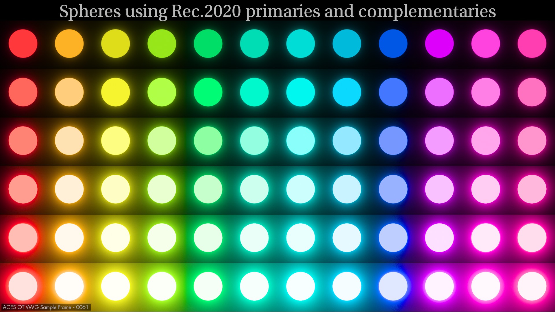
Then ACES 2.0 with the “chromaticity-linear approach” but with some loss of tonality in several areas such as reds and blues (notice the harsh line in the bottom row of the blue sphere):
And then ACES 2.0 with my LMT (I tried to improve the overall smoothness but actually made it worse in the blues and yellow purity compression is too high):
I really like these simple examples because this is where it is easier to spot where/how the Picture Formation falls apart or not. Finally, I will share some examples of gradient (using volumetric lights) where I was not able to achieve the desired result.
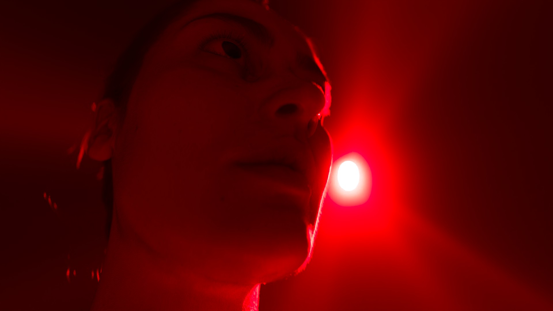
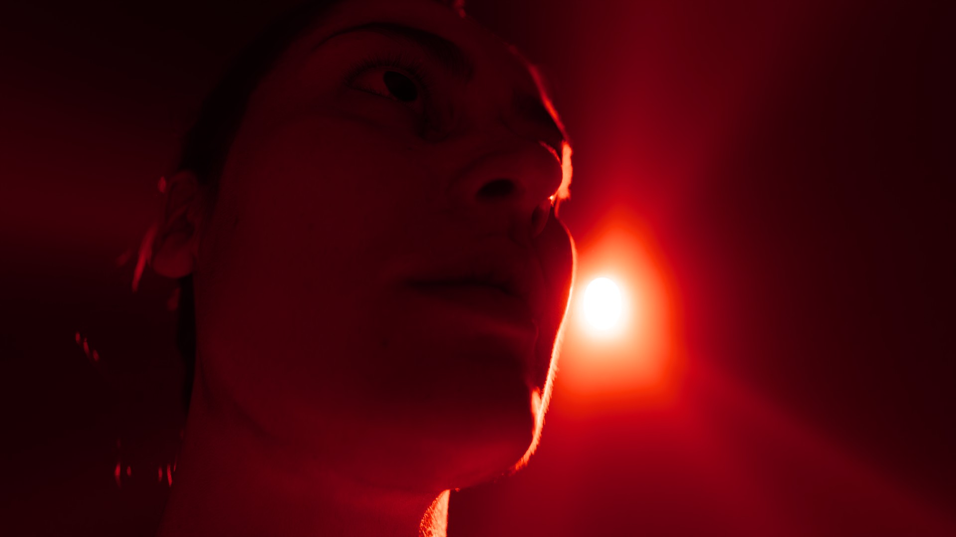
This is an ACEScg red primary light with ACES 1.X:
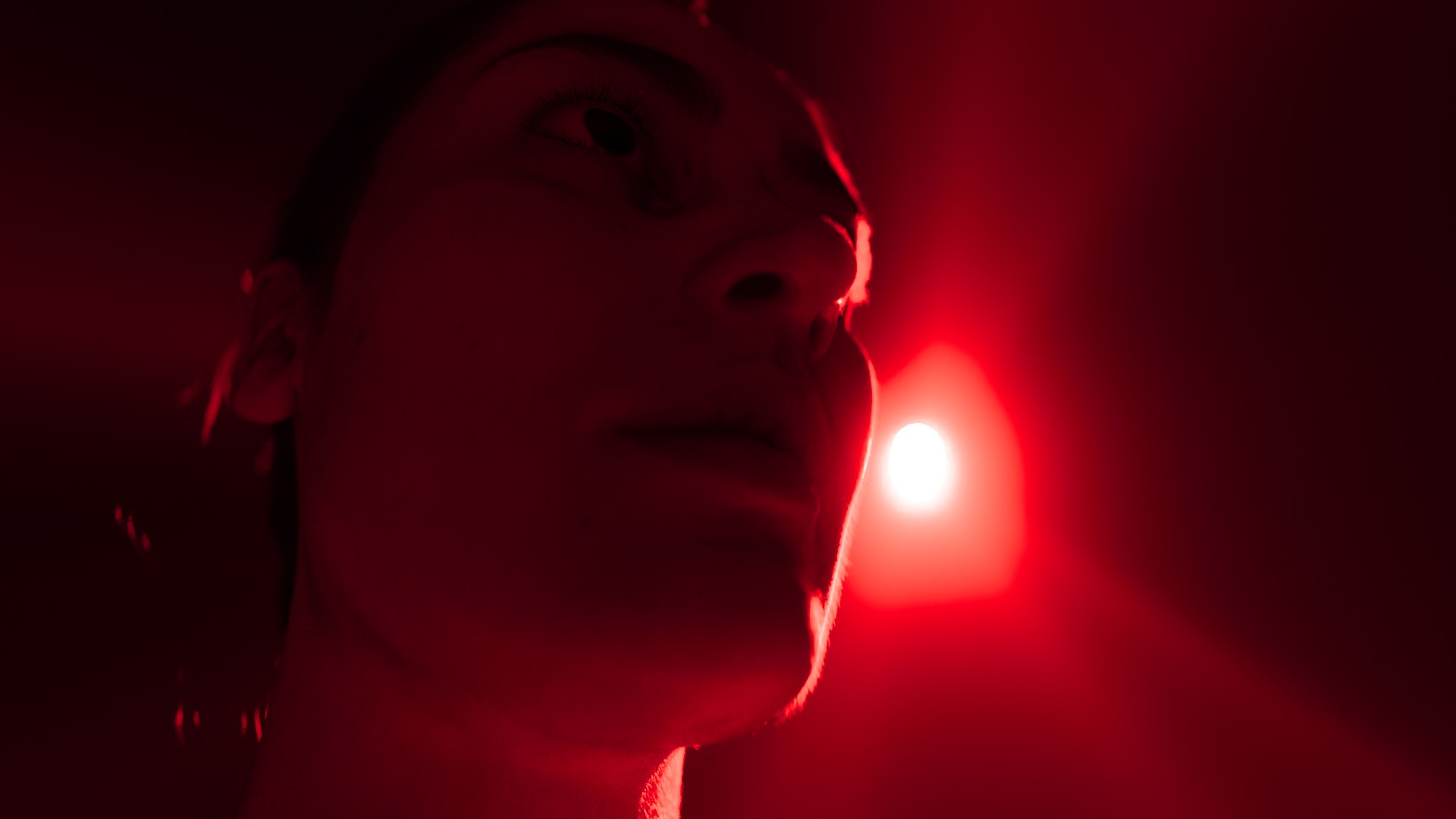
This is an ACEScg red primary light with ACES 2.0 (notice the ring breaking the tonality):
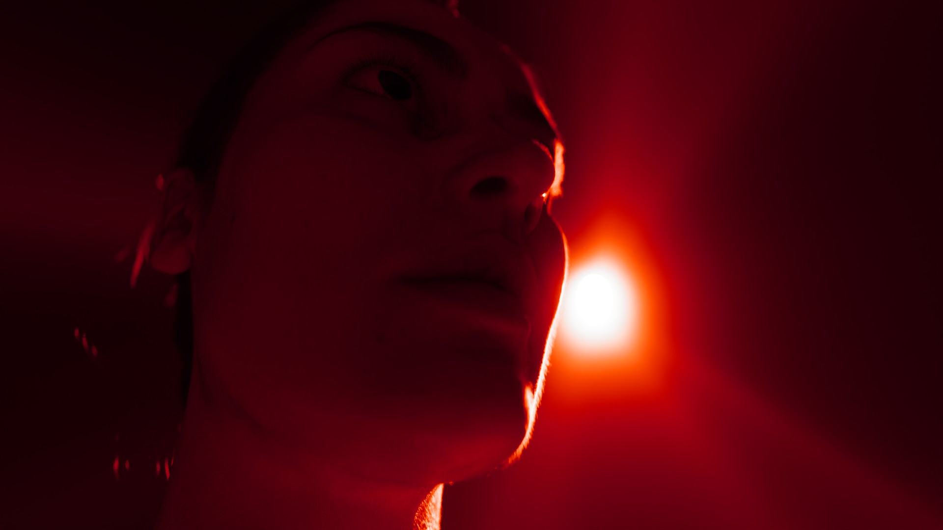
This is an ACEScg red primary light with ACES 2.0 and my LMT (I kinda improved the smoothness here but I created this massive white flat area):
This is the “visual target” I was trying to achieve (JP2499):
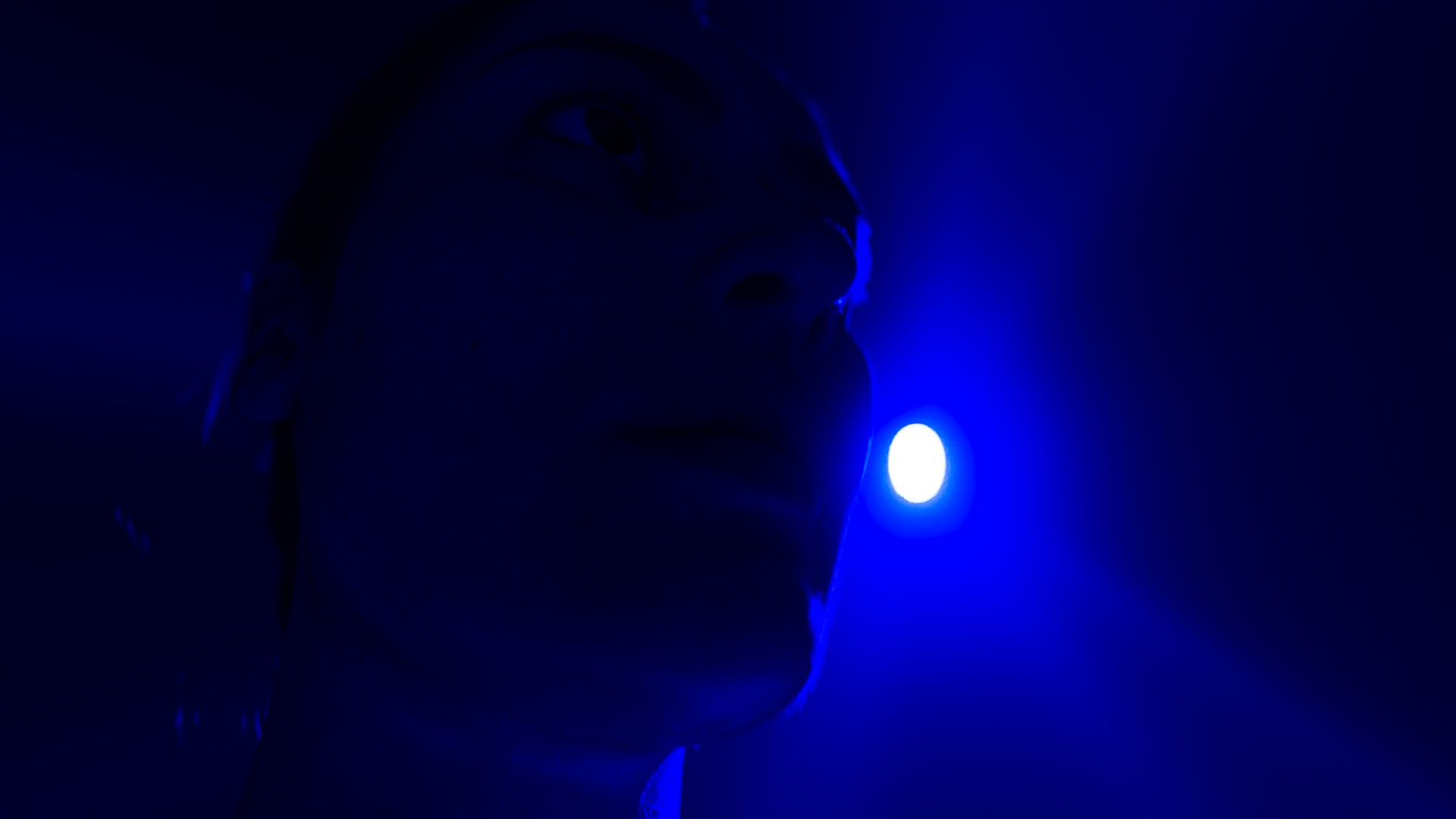
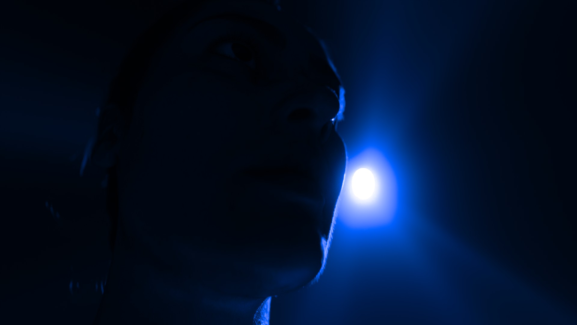
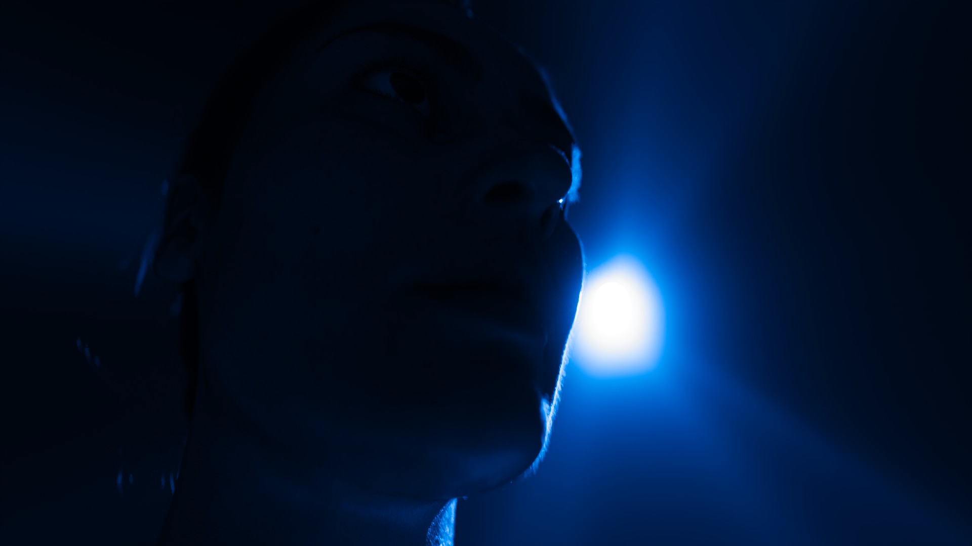
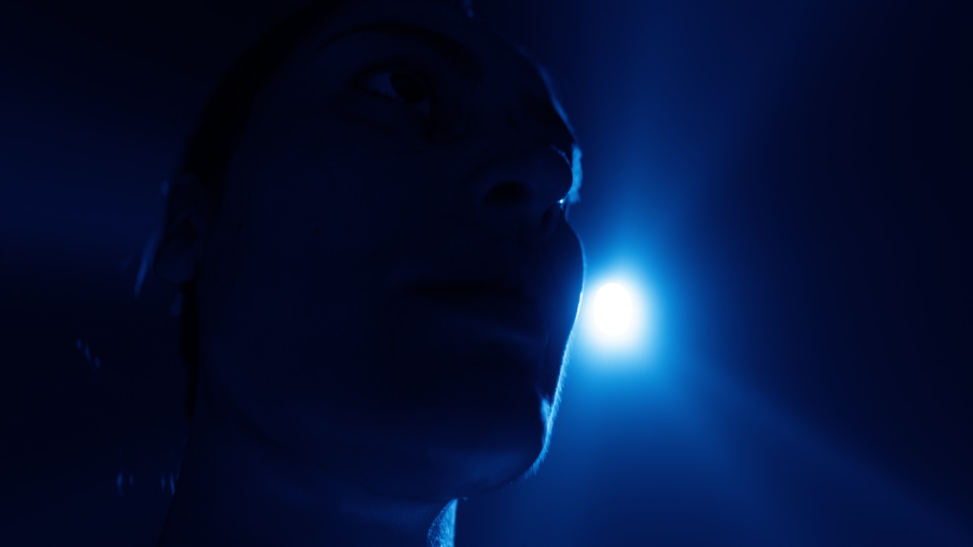
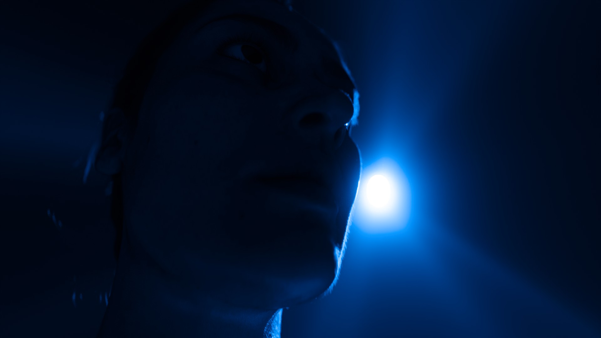
I have very similar results with an ACESg blue primary light (following the same order):
Apologies for the long post… I will just wrap up with some final thoughts:
- My approach is “limited” in the sense that I did not check any of this footage in HDR and I used a particular set of tools to generate the LMT. As a next step, I will try to use a completely toolset and see if I can improve my LMT. I will report back about this next attempt.
- Personally I would not recommend to use ACES 2.0 without a LMT. So the polarity flips and tonality disruptions observed in some of the examples above are improved .
- I think it would be nice to have a couple of LMTs available in some repo (or config) to help the artists in some of the areas shown above.
- Also, I would recommend that these LMTs re-introduce some “engineered hue path bending” so fires do not look salmon and avoid abney effect with blues for example. Just like the Alex Fry´s presentation from Electronic Arts.
About this last point, I will spare you all the details but I learned the hard way on the movie I am currently working on that “neutral does not look natural nor pleasing”.
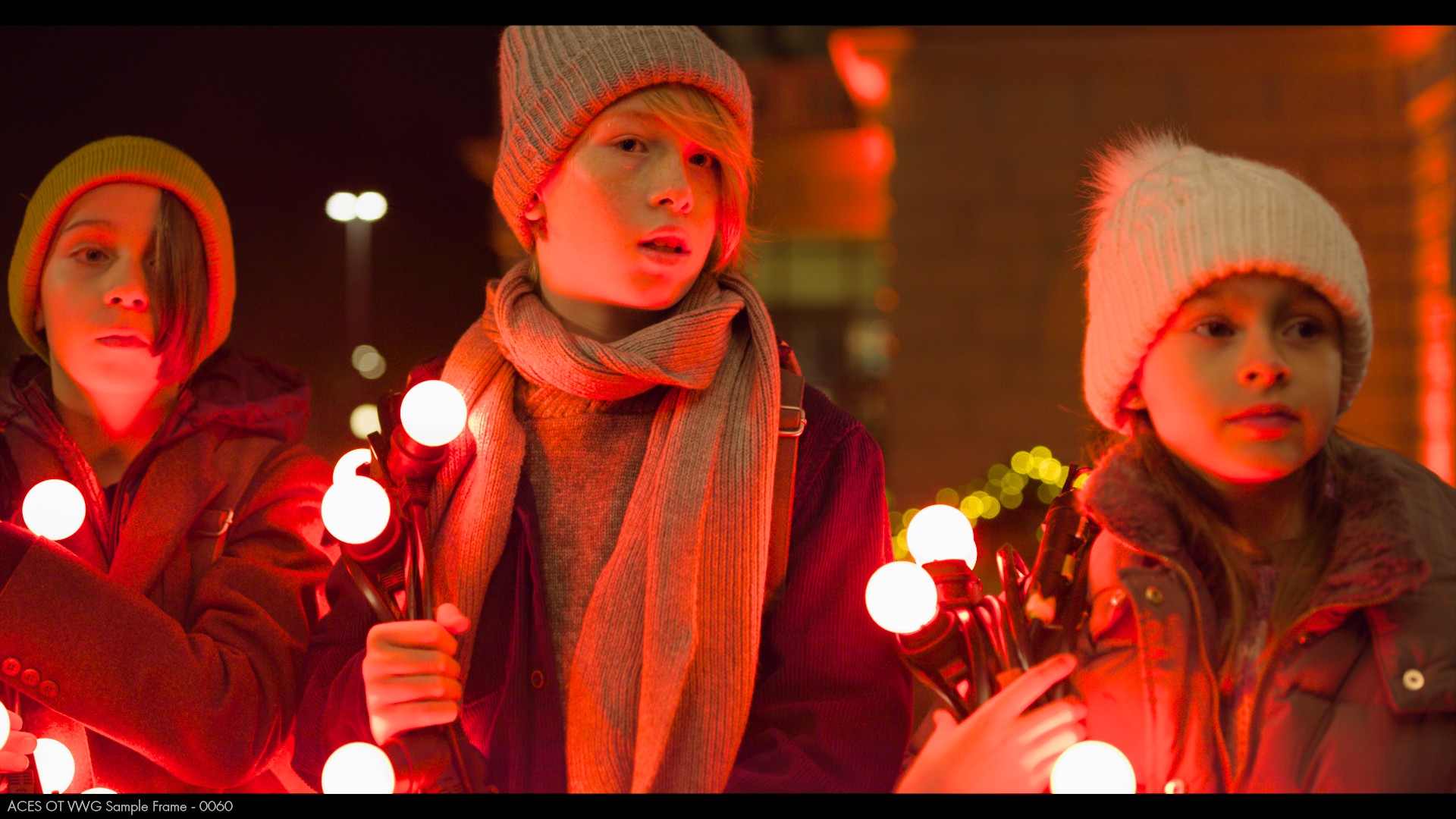
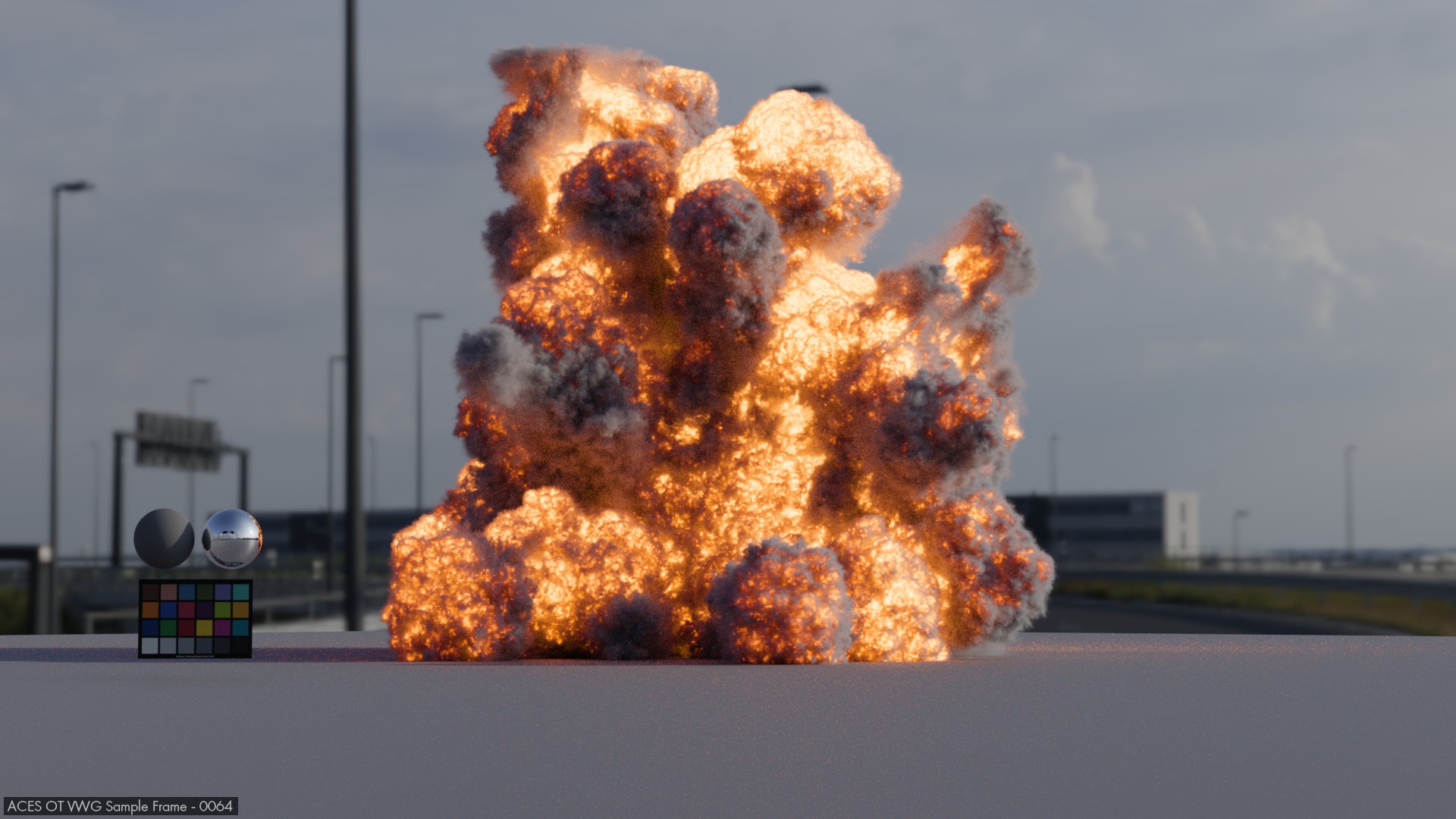
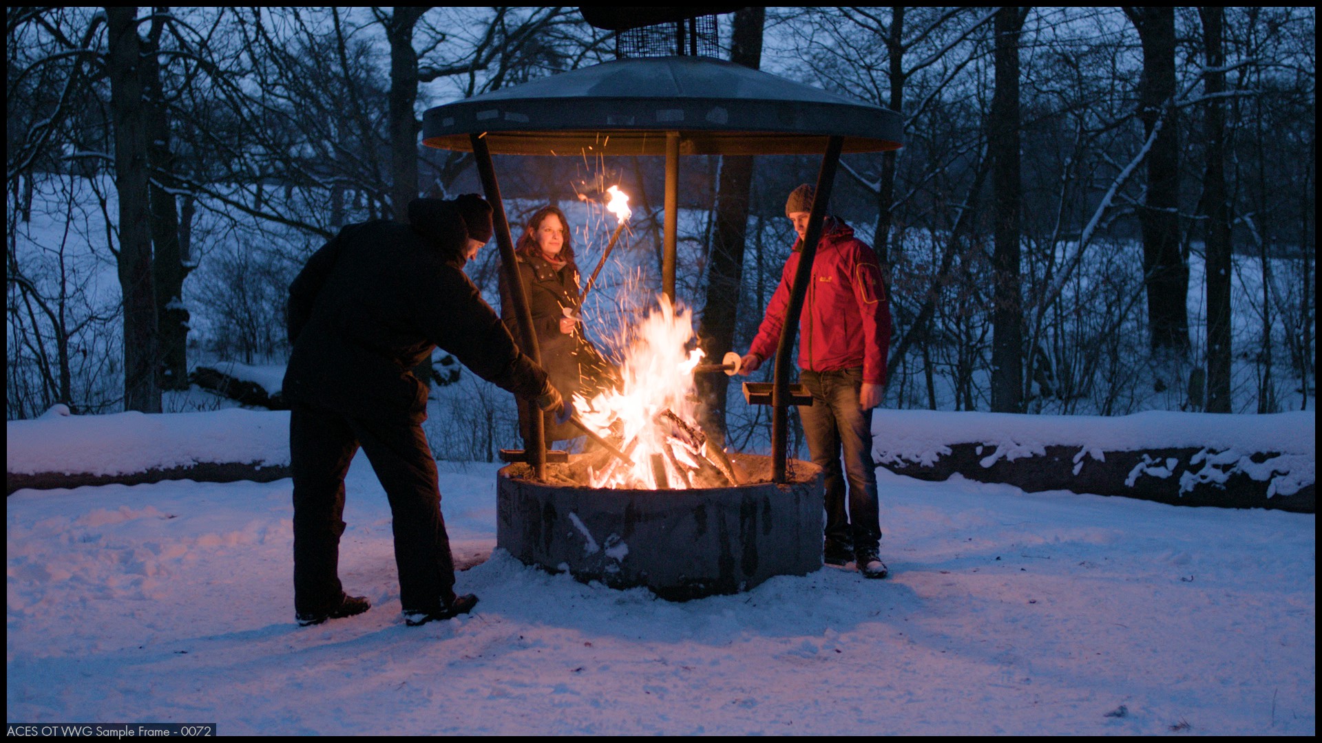
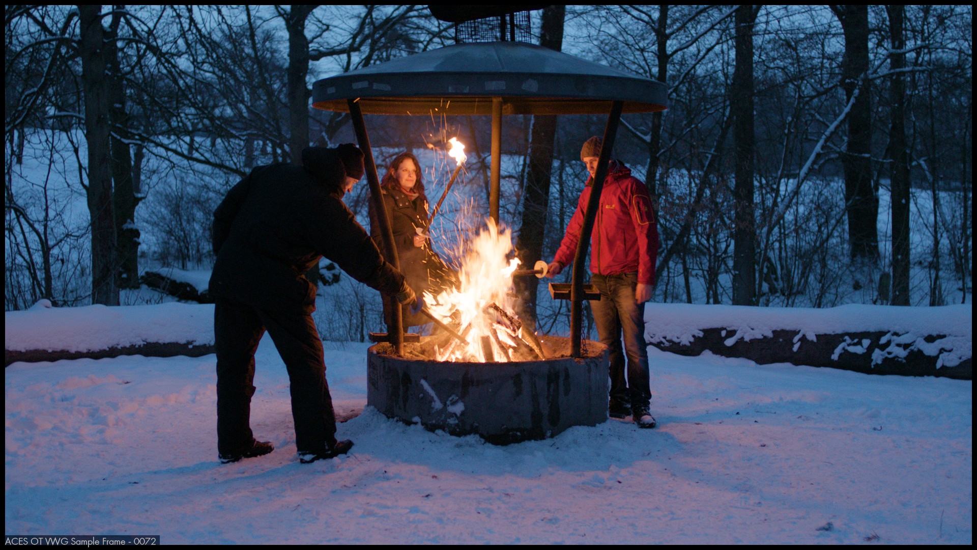
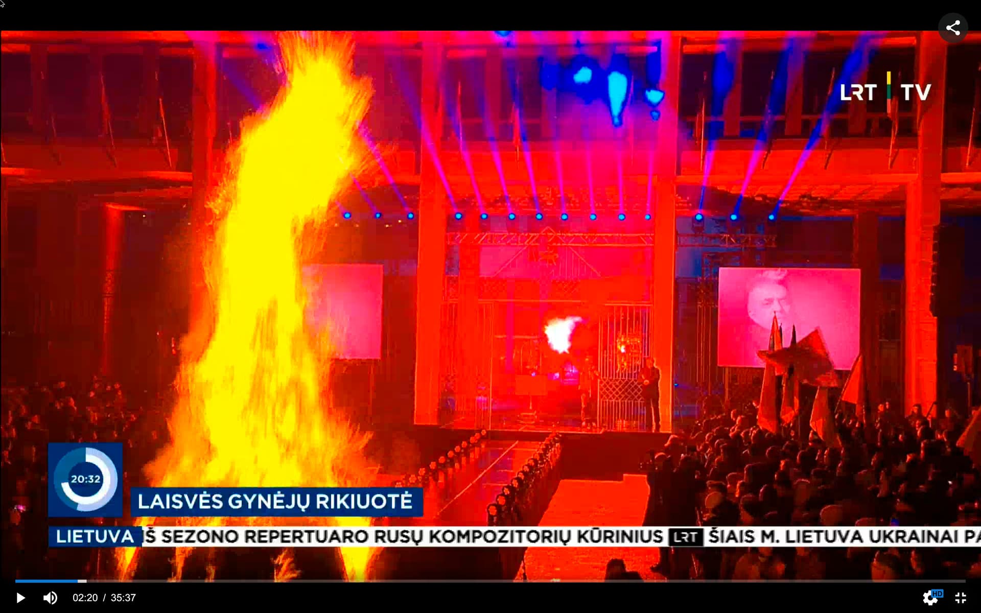
Here are the final examples regarding that matter:
ACES 1.X:
ACES 2.0:
ACES 2.0 with my LMT:
I think a good way to think about this is using the Planckian locus/Kelvin temperatures to generate some fire simulations and making sure they do not come as “salmon pink” (I think Liam´s example above uses this already). It worries me that FX artists have to compensate the Picture Formation behavior in their scenes (e.g. the stimuli ain´t the image).
Thanks !