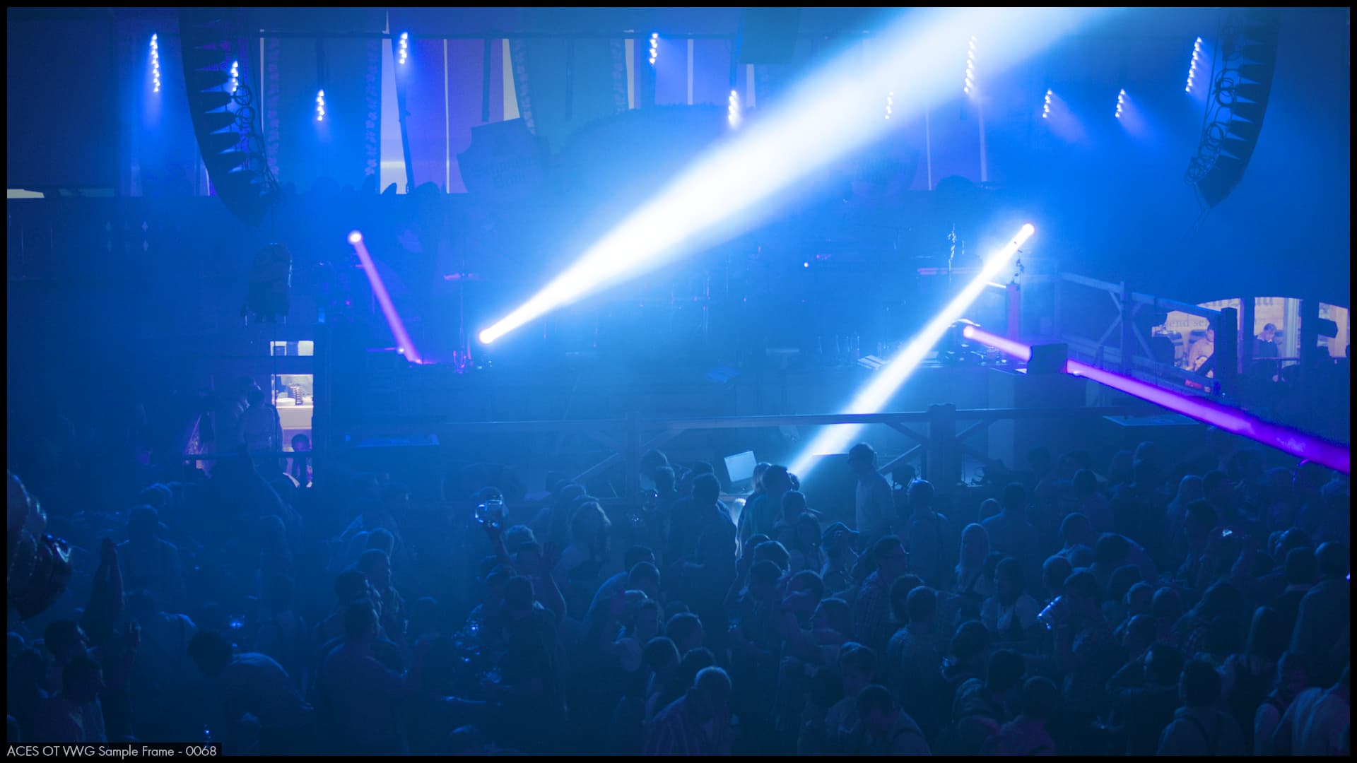
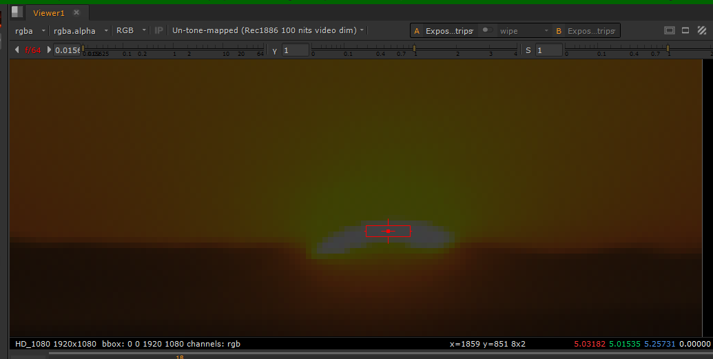
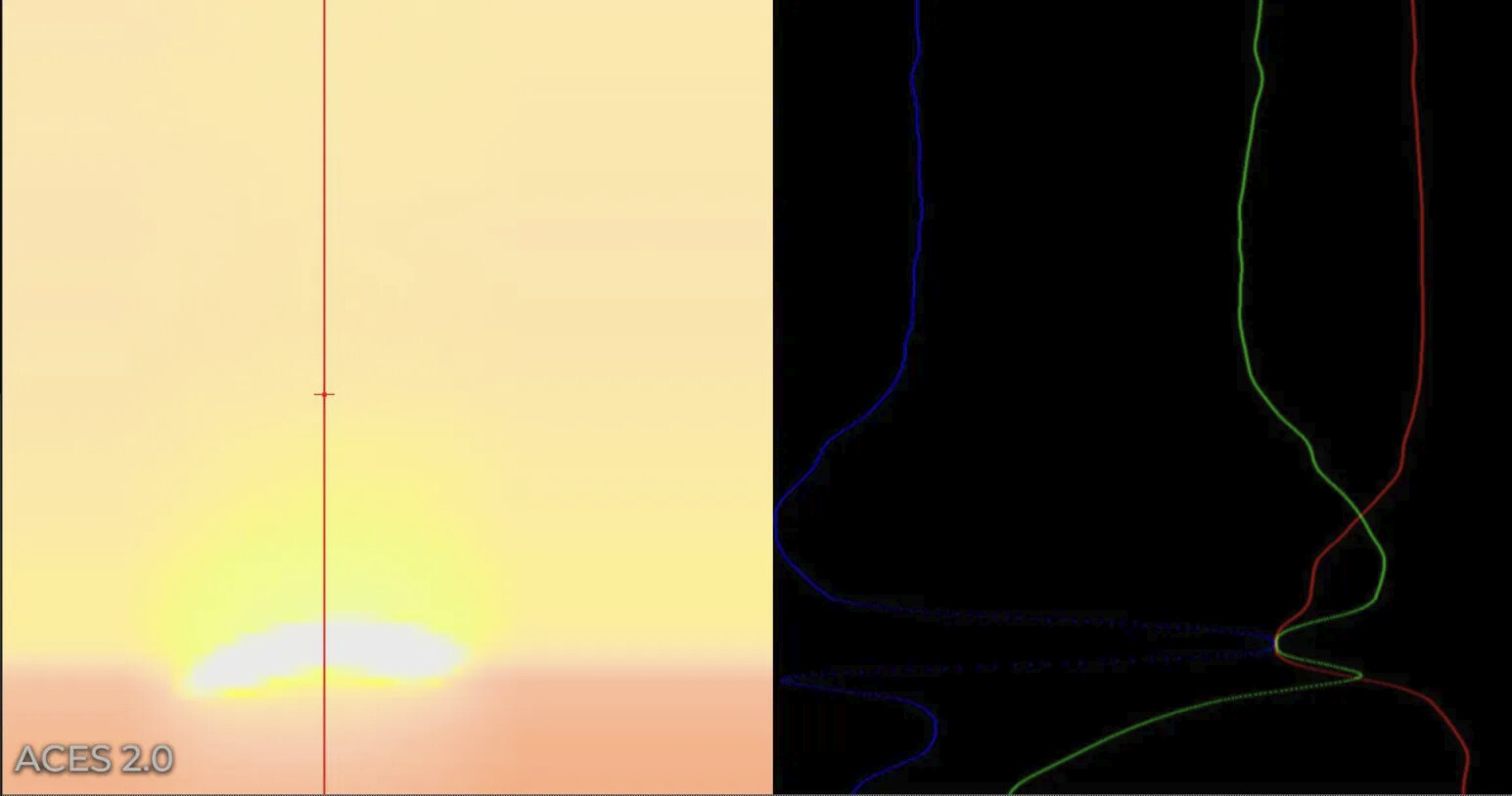
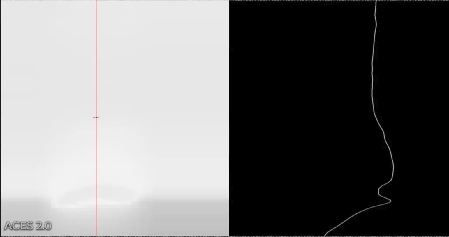
Sorry if this has been covered already. I was having a look at ACES V2 this AM using some of the ACES test frames and came upon some unpleasing results on 2 frames.
Note: I tested this with the blink script and a 64 LUT that we created from the CTL.
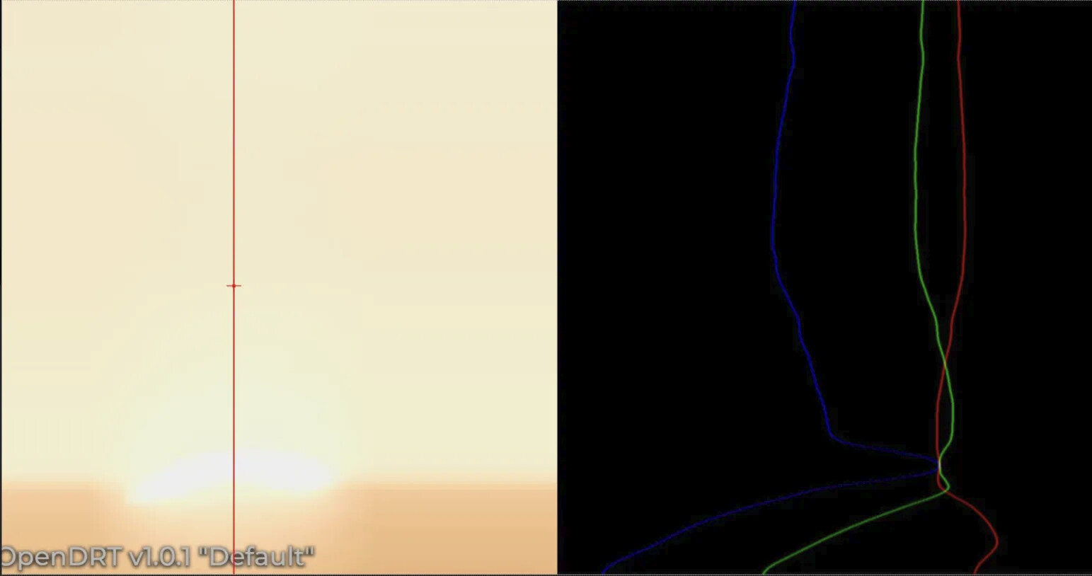
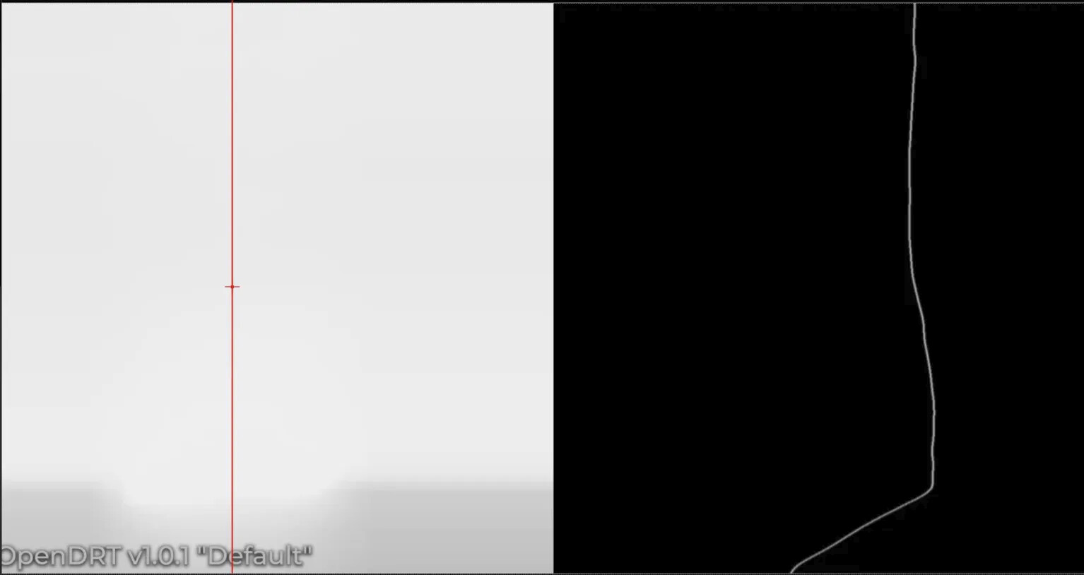
About the second issue, I think I reported something similar in this thread with the blue gradient example.
This answer was given to me back then :
But I would just expand on it to say that we sacrifice having a nice image appearance for every possible source image “out of the box”, in order to hit the corners and be invertible. You can of course use an LMT which “rounds off the corners”, and will therefore smooth out the appearance for extreme images such as the pure blue example.
Noted. TBH this is the answer I was hoping/expecting to get. Very well aware that we can’t get it perfect on all situations. First image is certainly clipped but roll-off would need to be adjusted then.
I know this is not ideal. There were requirements in the design of ACES 2.0 that had to be taken in account and eventually led to compromises.
What I would be curious to know is if some LMTs are planned in the long course. I think they would be helpful and even necessary in some cases. I brought this topic a couple of times already.
Thanks !
I’m a DaVinci Resolve user, so I’m not sure if those are the same. I don’t have dedicated a blue highlight fixing LMT. Resolve has an ACES neon suppression LUT that seems to take the edge off really extreme colours.
The Resolve Neon LMT is the “blue highlight fix”. It was the initial fix intended for ACES 1 before the more rigid RGC was developed. It compresses quite harshly and tended to affect values in the more usable ranges too much. It is not really intended to be used anymore in an ACES 1.x pipeline and definitely not in ACES 2.0, neither is RGC from what I’ve understood, despite Resolve allowing this in their software.
For ACES 2.0 there currently aren’t any official additional tools to address certain appearance issues, but during it’s development @nick made a LMT JMh Blue Compress designed to operate in JMh which is the model ACES 2.0 uses in it’s rendering. It’s called blue compress but it has a hue slider so it can address any angle really. Might be worth giving a go.
Just wanted to clarify that the RGC remains compatible with ACES 2.0. There are no recommendations either for or against its continued use in ACES 2.
We think that ACES 2 “out of the box” will remove the need for the RGC in most cases because the gamut mapping that is a part of the ACES 2 transforms handles the same problematic colors (albeit in a slightly different way). ACES 2 also uses AP1 to define a number of boundary restrictions. Therefore, using the RGC to map very erratic scene colors into AP1 as it was originally designed for would probably not be a bad thing. I don’t think it would harm anything to continue using the RGC.
Either way, Resolve should certainly not remove the RGC as a potential tool for the user in scenarios where it could prove useful.
Many of the problematic images that previously required the RGC in order to look reasonable through ACES 1 transforms can also look reasonable through ACES 2 transforms without needing the RGC.
Wow! I really decided to check back on ACESCentral at the right time. It turns out that I debugged ACES 2.0 extensively because we were really bothered by these artifacts at Netease but one internal studio really wanted the chromaticity-linear behavior of ACES 2. That studio had other requirements which were not met by the final ACES 2 so I ended up bisecting each component of it until I figured out what was causing the following two issues:
Too much desaturation both in SDR and HDR
Color breakups
The extreme amount of desaturation is caused by the new chroma compression which was changed multiple times during development. You might be able to put a LMT that does chroma compression in a way that you like then apply the reverse chroma compression from final ACES 2 to fix that one before the final node in which you apply the ACES 2 transform in Resolve.
The color breakups are more annoying to fix. They are caused by a combination of the extreme chroma compression and an imprecision in the approximate gamut compression. The best we found was to revert back to the iterative gamut compression that was in v39 code. Note that we fixed Reach/AP1 compress mode of later versions to work correctly with the iterative gamut compressor.
These fixes have been tested on a DisplayHDR 1600 monitor (real measured peak 2000 nits) with 87% Rec.2020 gamut reproduction and hold up pretty well. They also hold up nicely in SDR too even though it still desaturates too much for our tastes and we chose another path for HDR->SDR.
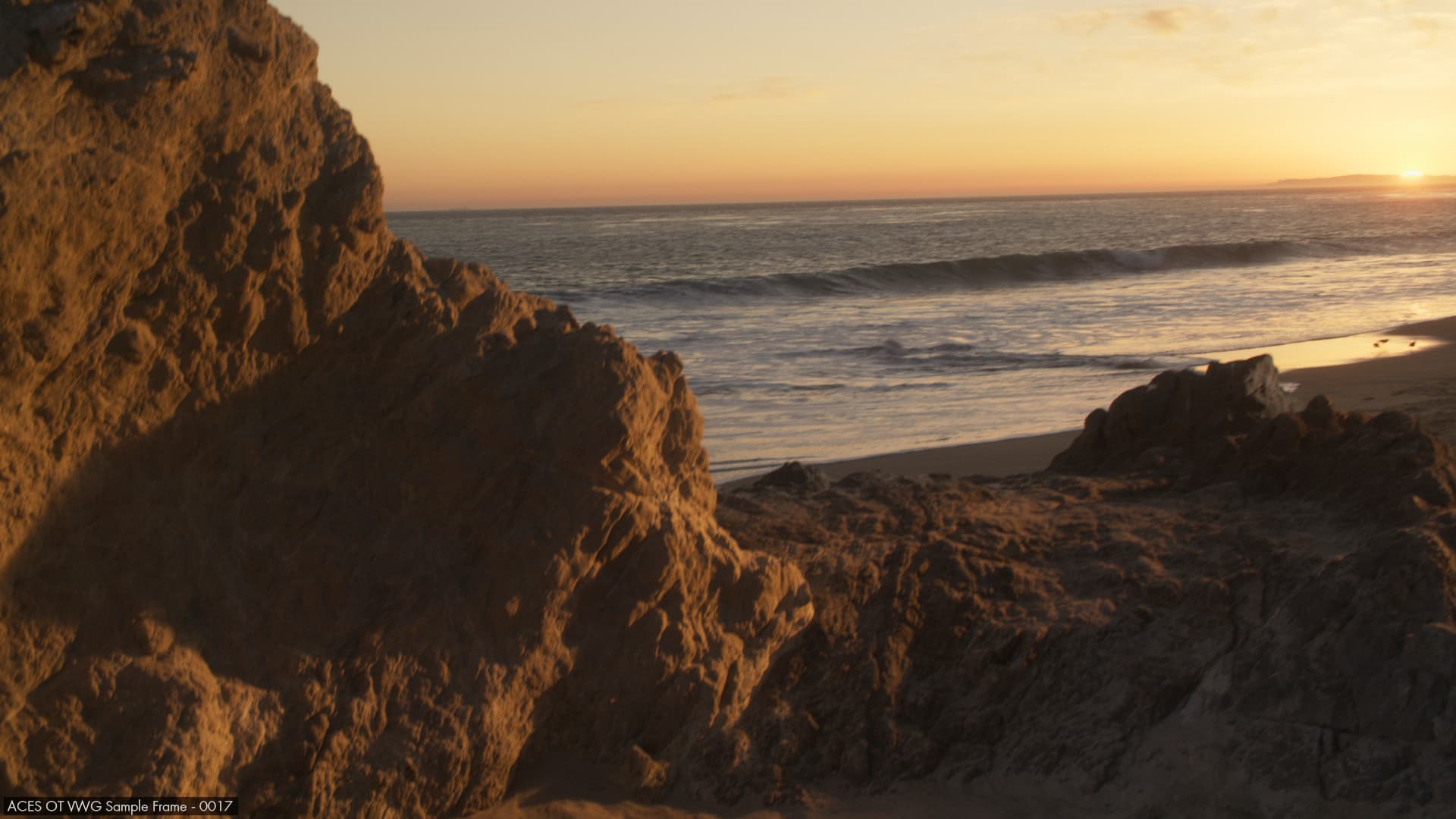
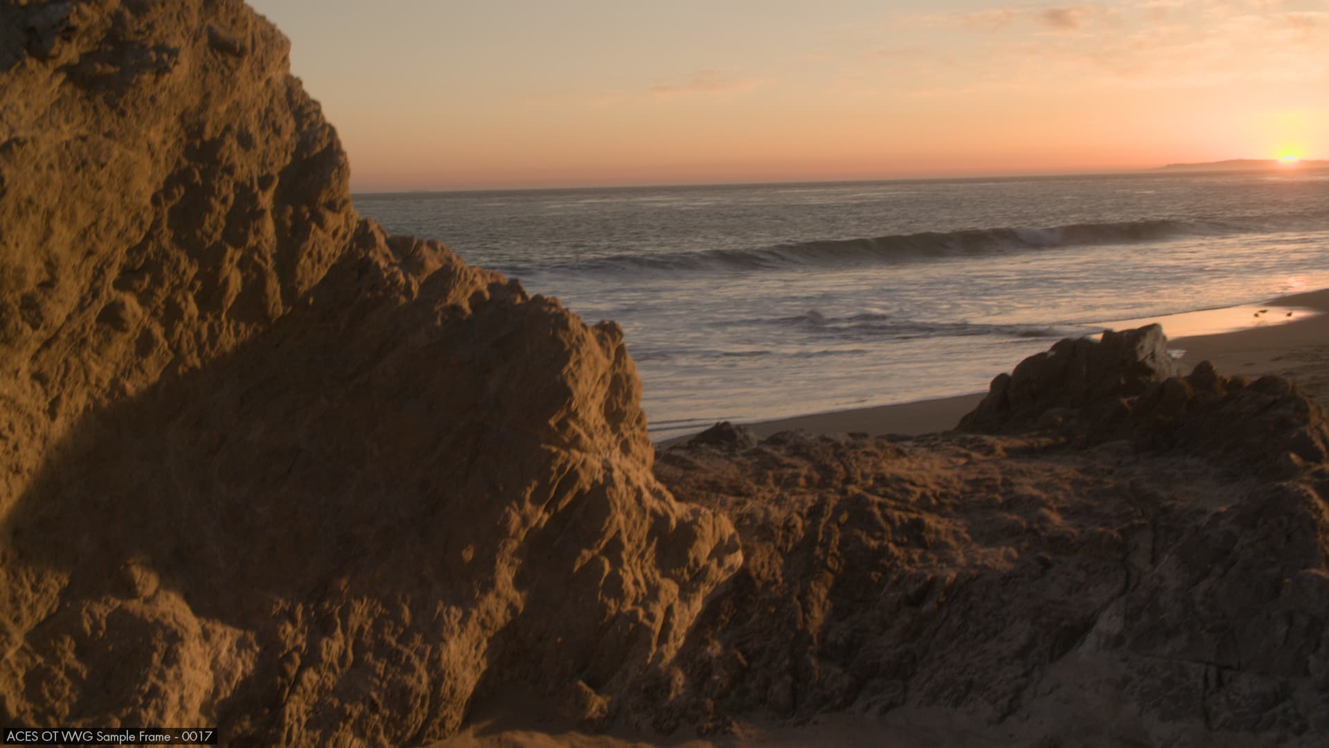
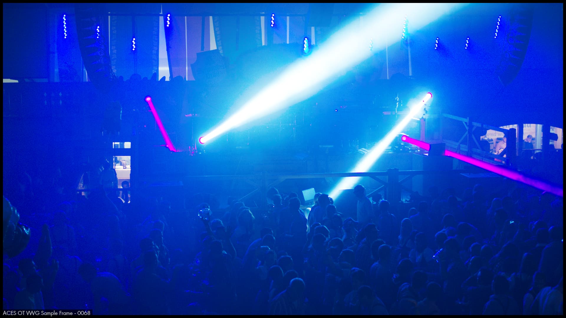
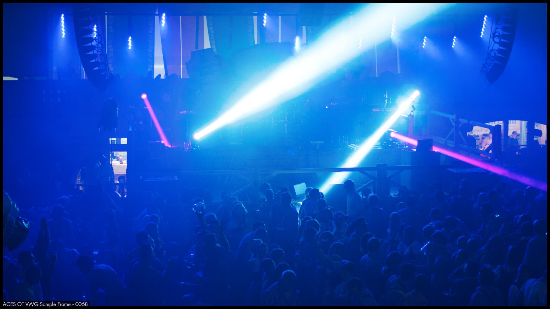
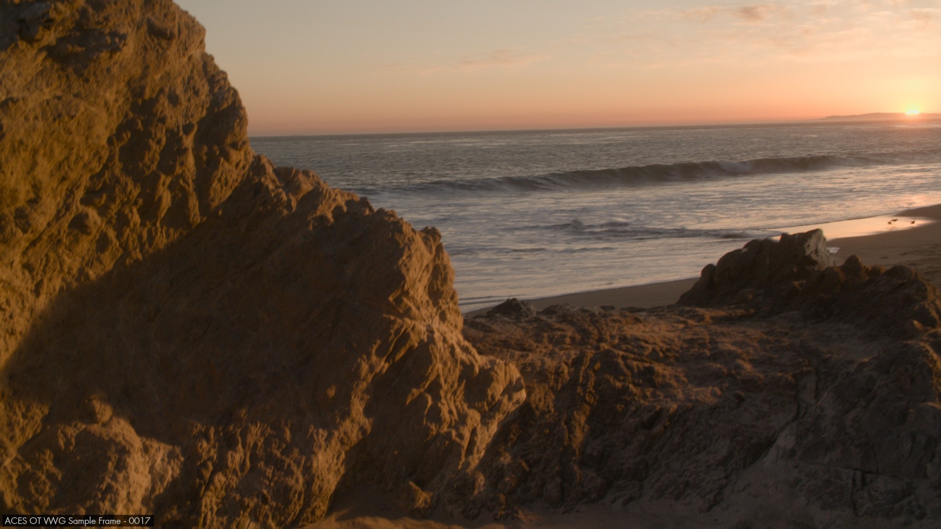
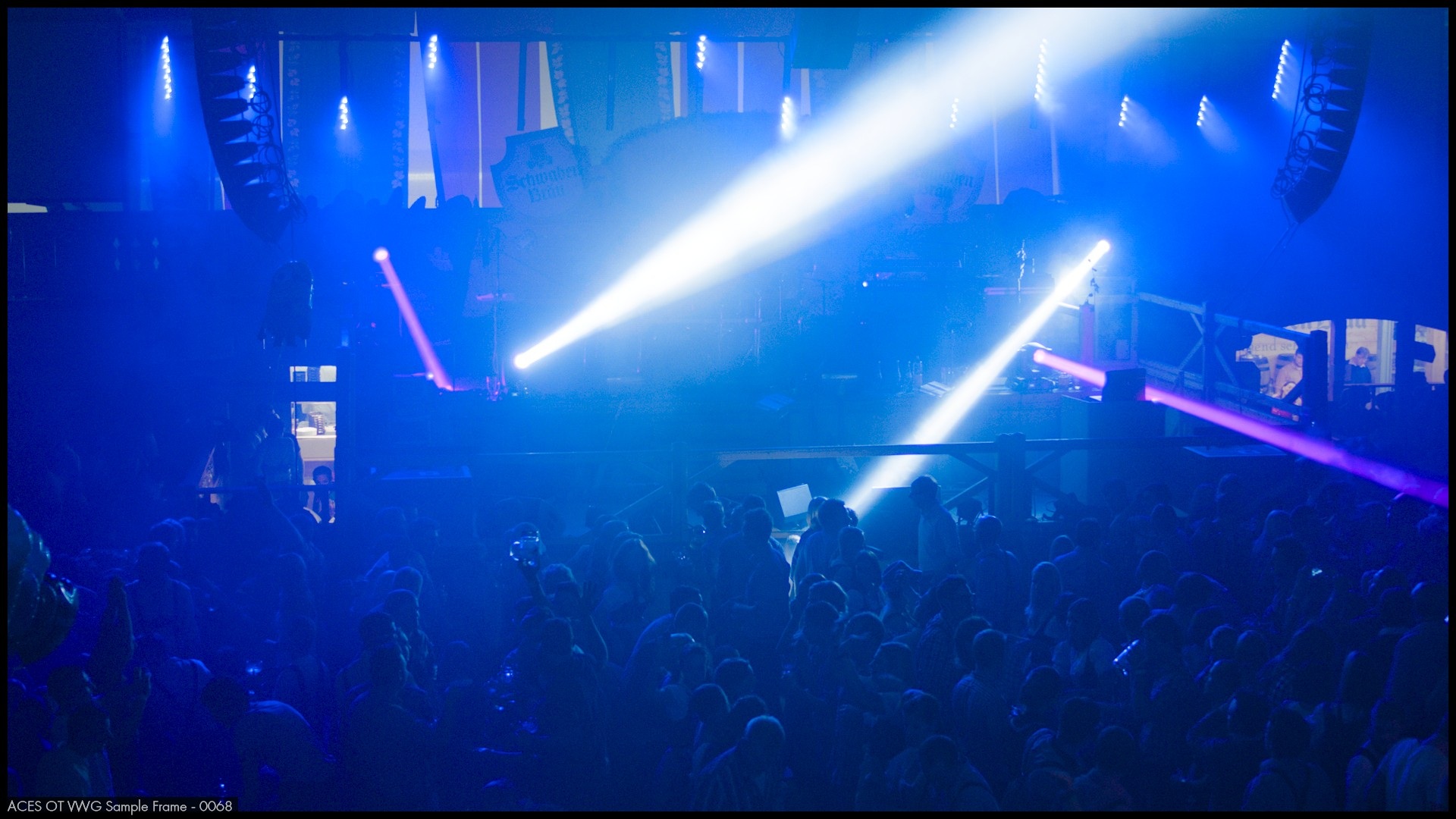
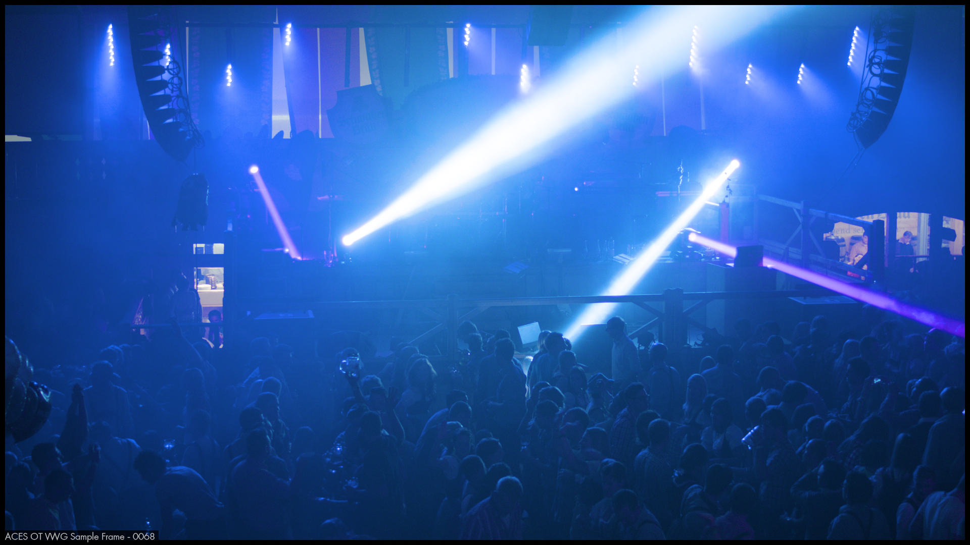
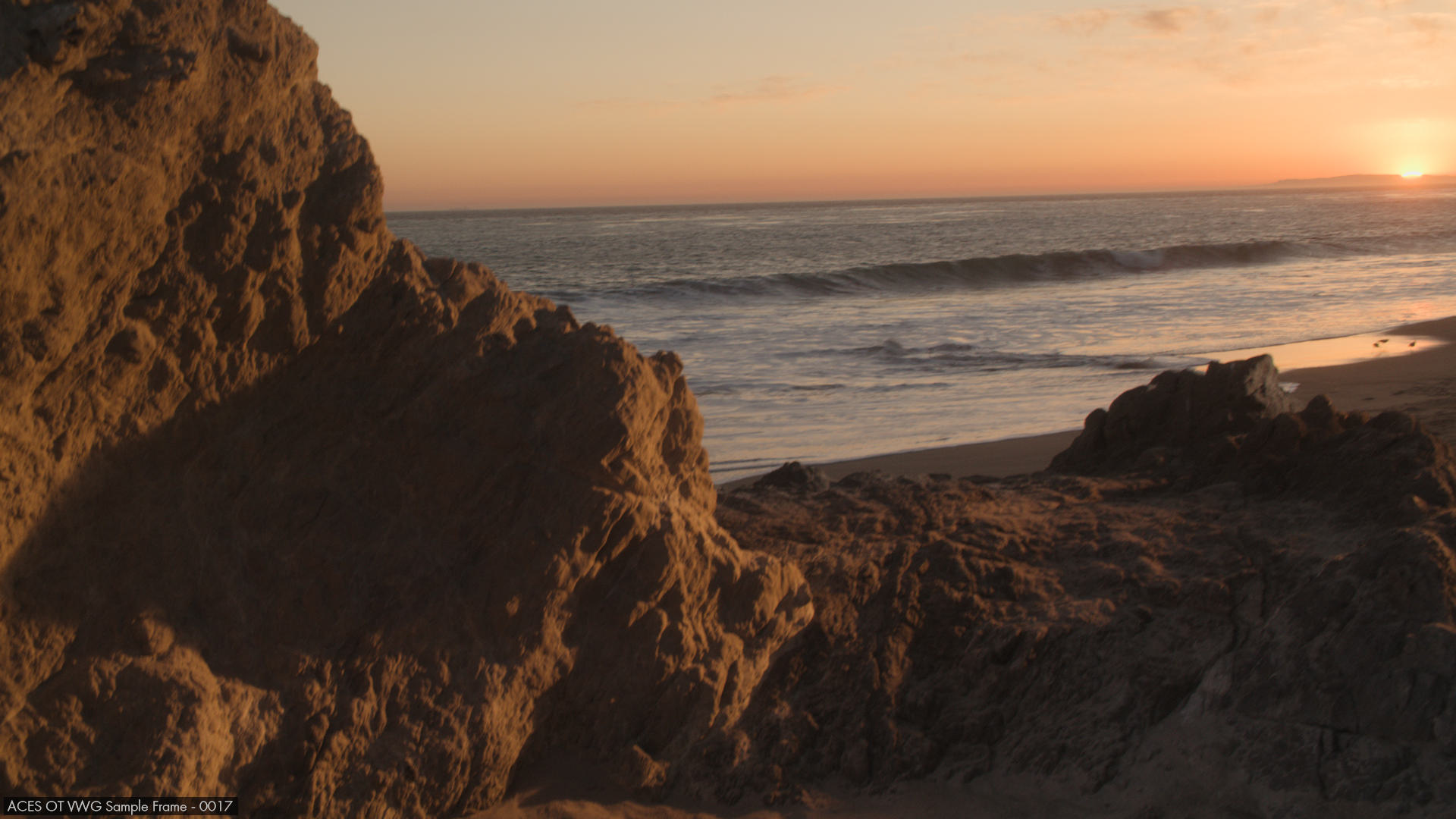
Here are SDR using my custom DCTL for your two images:
Note 1: I used 709 instead of my typical practice of using sRGB as I assumed this is what you did.
Note 2: The second image still requires an ACES Parametric Compress node before I apply my custom DCTL transform node and that parametric compress node is also active in the first image but it doesn’t change the result since I made it compress much less than the reference compress.
Note 3: These images are produced using the SDR parametrization of the custom transform and are not using the hinted at alternate HDR->SDR path. This alternate path is proprietary.
If anything, applying the RGC makes the beach image look worse around the sun. I’ll be away on vacation for a few days but, as soon as I come back, I’ll modify one of my DCTL to use the final ACES 2 code — there aren’t that many major changes from the v58 prototype which is the latest one I ported (with full dynamic generation of the look-up tables), and fix for AMD. I’ll also make a version of the custom DRT I used earlier where I fixed it for AMD and removed the proprietary SDR path (which was not used in my post above) so I can post both in addition to a diff. My custom one is 70-80% similar to the final one. I’ll explain the differences in detail in the diff but it’s mostly using components from older iterations of the DRT, sometimes with slight fixes.
I think that’s the longest Aces Central post I have ever seen. And way to technical for me! But there’s one example in there that looks exactly like what is happening in the beach image.
It’s really not. It’s just a tiny departure from the orthodoxy around imaging circles.
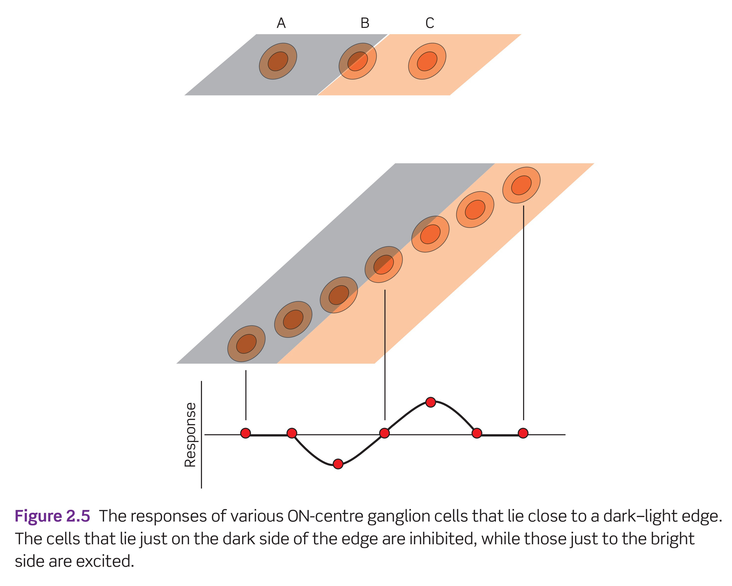
As I’ve tried to point out on this forum, the key entry point is to have an appreciation for how the lowest order signals are formed. They are not discrete quantisations of the stimuli, but rather a gradient domain signal in increment and decrement channels.
This diagram1 shows the structure of the signal elegantly.
It is for this reason that some of us believe there is a crucial flaw with how we conduct 3x3 matrix stimuli gaining in terms of cognized results. I believe @jedsmith has done rather extensive demonstrations on this, but I’m unsure many folks will appreciate the implications until I’ve long since expired from this planet.
Polarity is perhaps the singular most important structure to our lower order signals in terms of visual cognition, and is the entry point to dismantle all ideas around Cartesian “Colour Appearance Models” and “Uniform Colour Spaces”.
— (No this is not AI generated just because I used an em-dash dammit!)
1 Snowden, Robert J., Peter Thompson, and Tom Troscianko. Basic Vision: An Introduction to Visual Perception. Rev. ed. Oxford: Oxford University Press, 2011. Pg 54.