Luminance-Chrominance Polarity Based Display Rendering Transform

Hi,

a few weeks back when @Troy_James_Sobotka presented some ideas after one Wednesday meeting. I contacted him afterwards and tried to setup a small and simple scene in Blender to understand one of the issues a bit better.

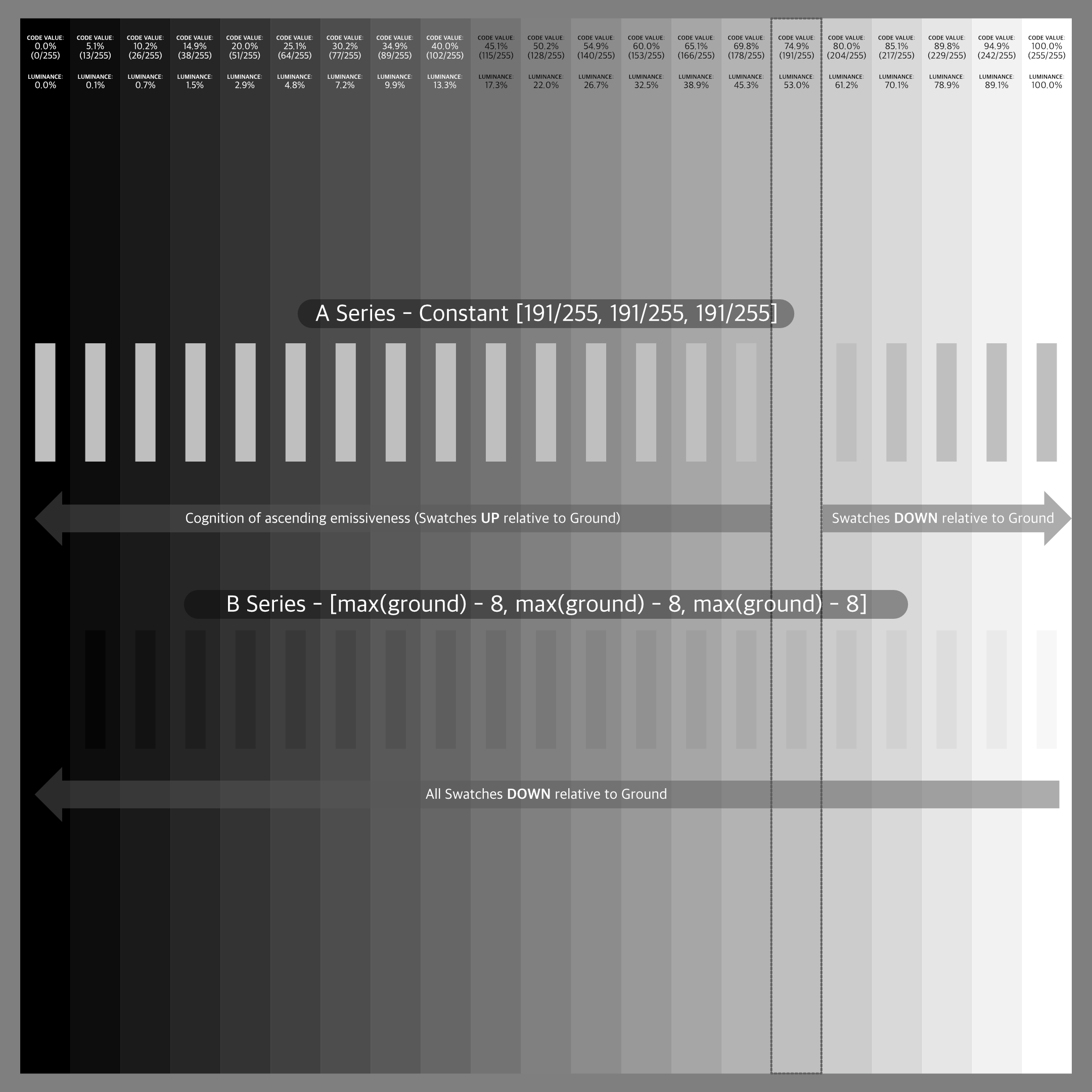
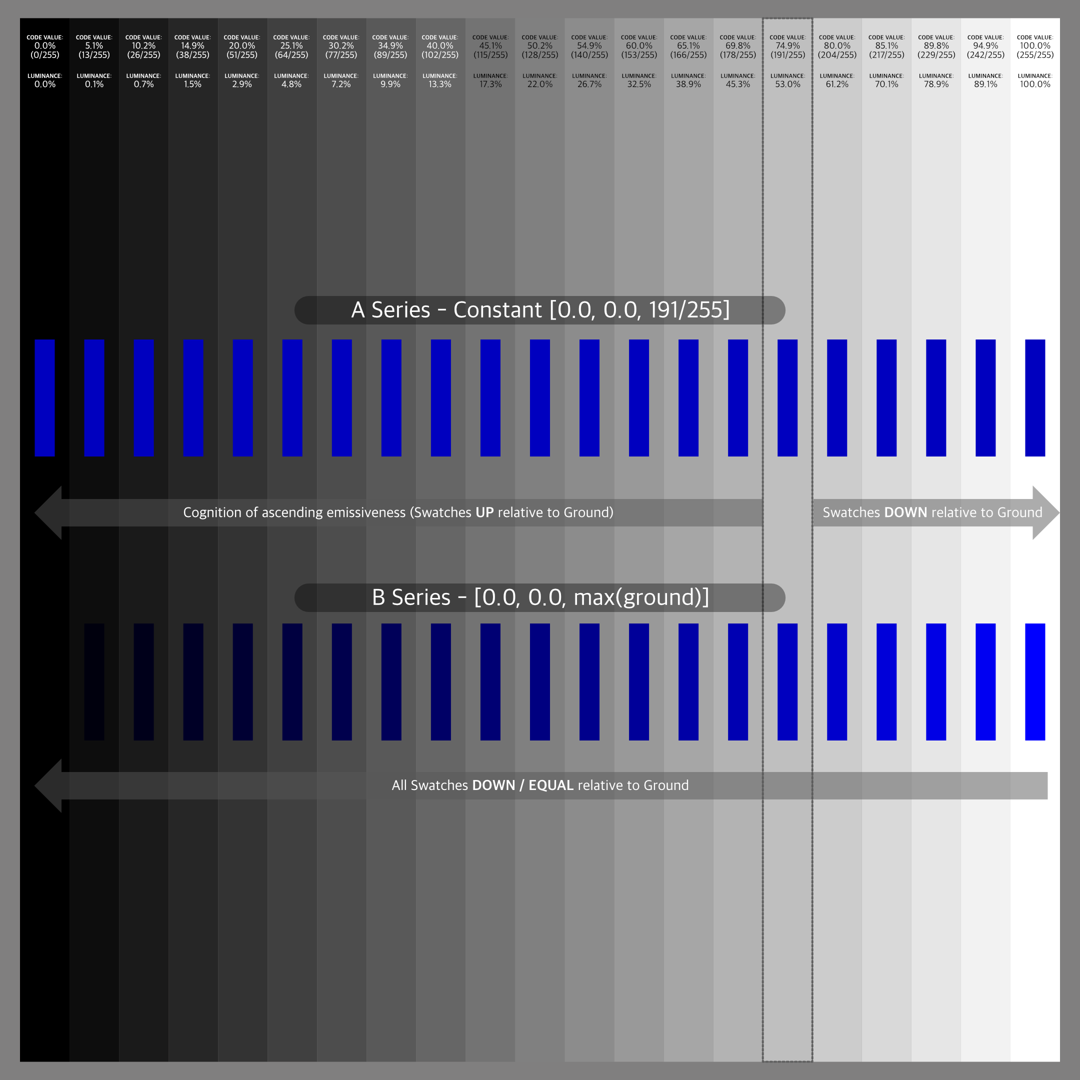
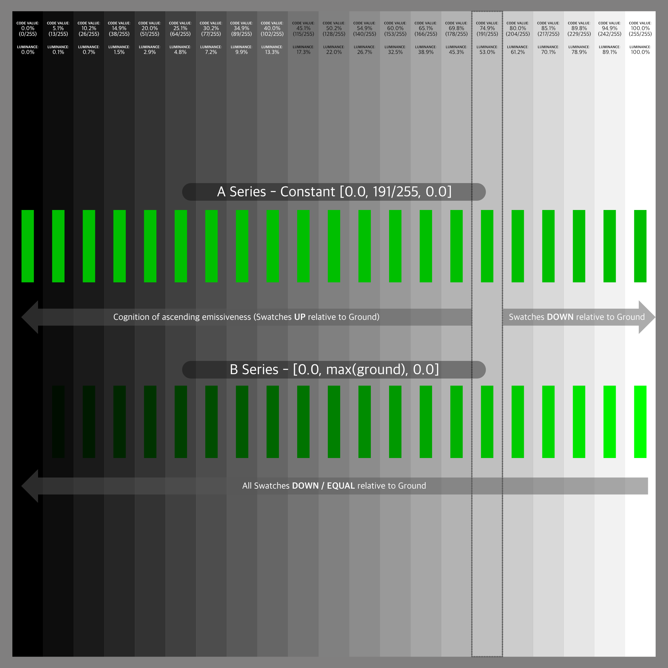
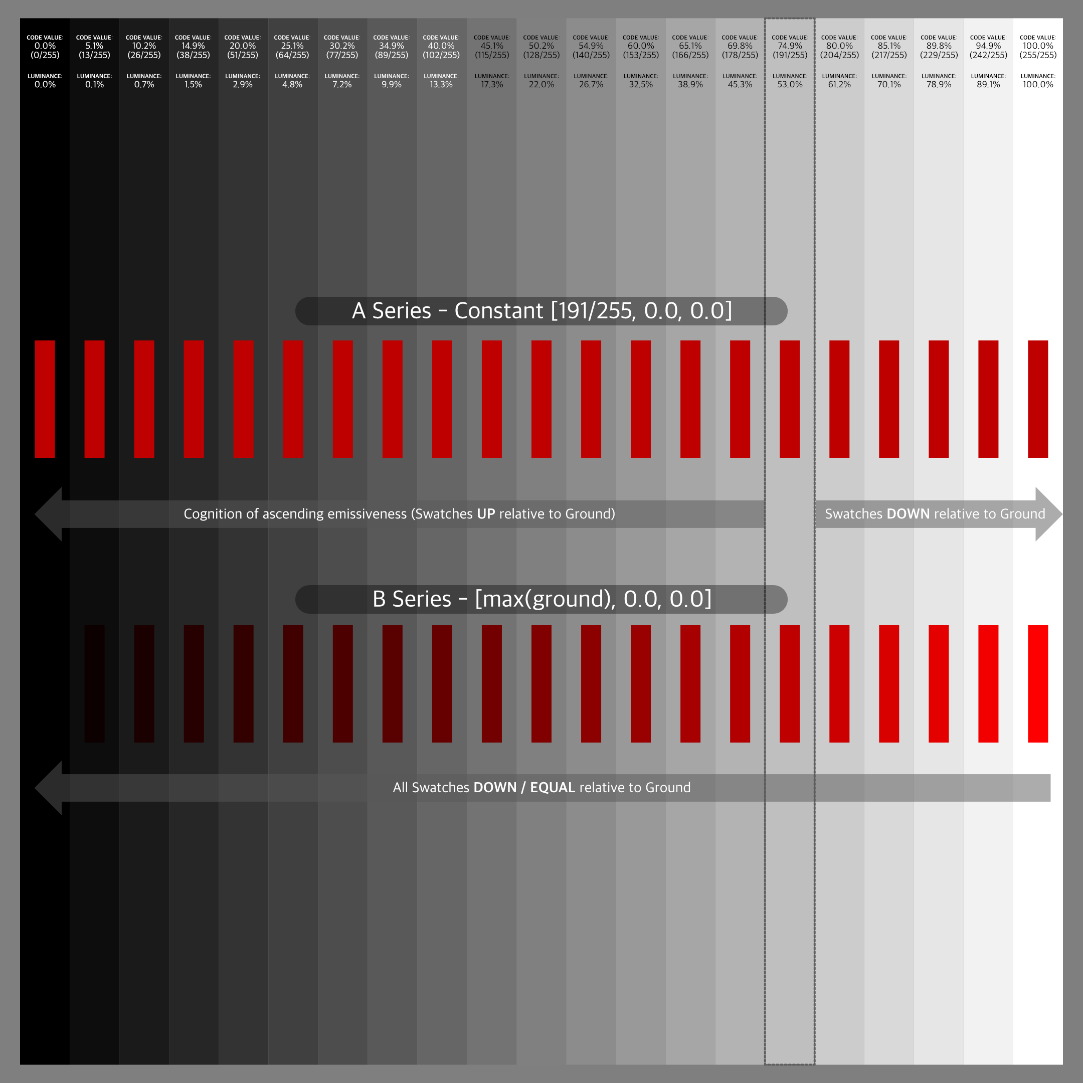
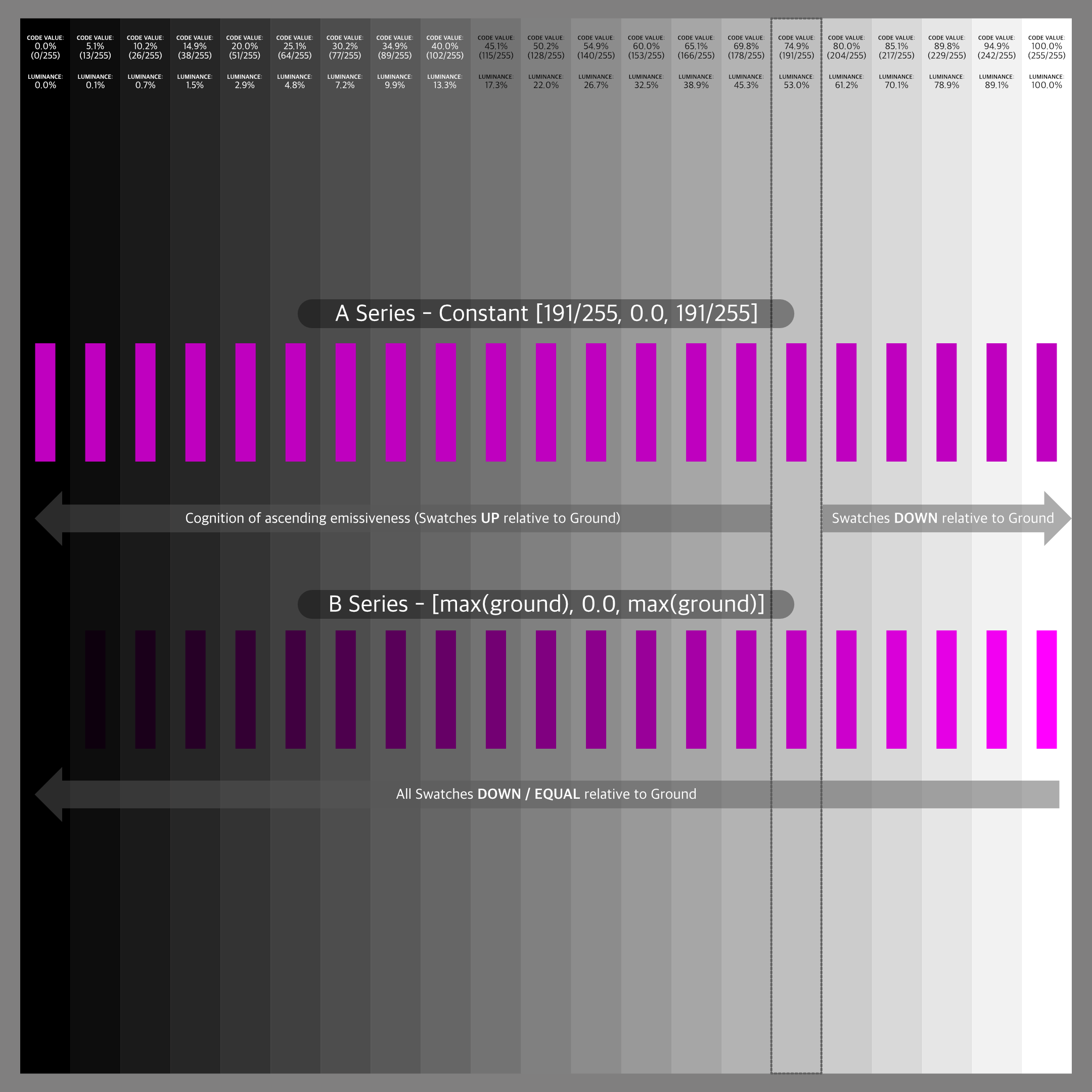
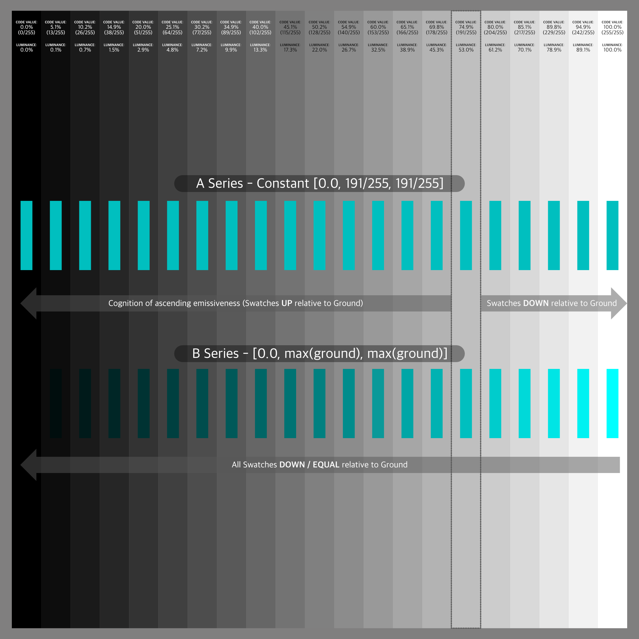
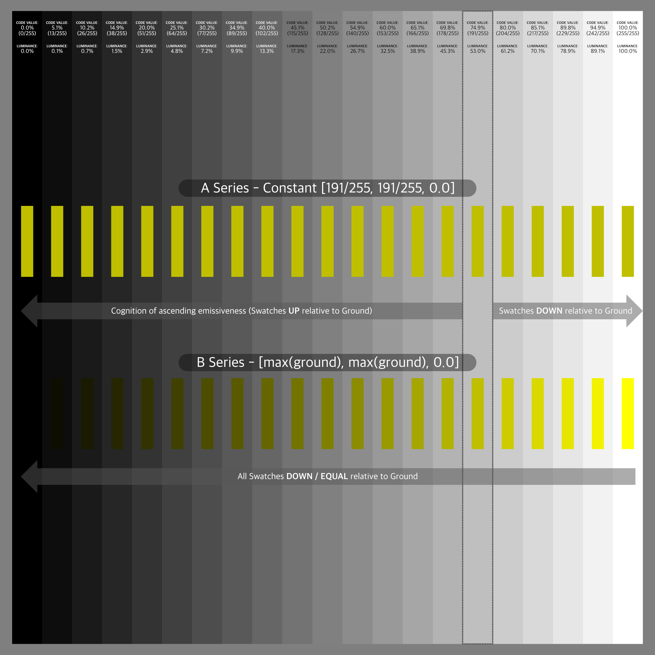
The setup is using a PBR shader to simulate a full reflective achromatic (white) wall. The wall is only lit by one achromatic (white) area light. The fall off of the light is creating a gradient. Next I set three rows of 100% (very rough) reflective red, green and blue dots. They also are being lit by the area light. I render two passes, one for the “white” stripes and one for the dots. The blender scene is set up in standard linear sRGB/REC.709.

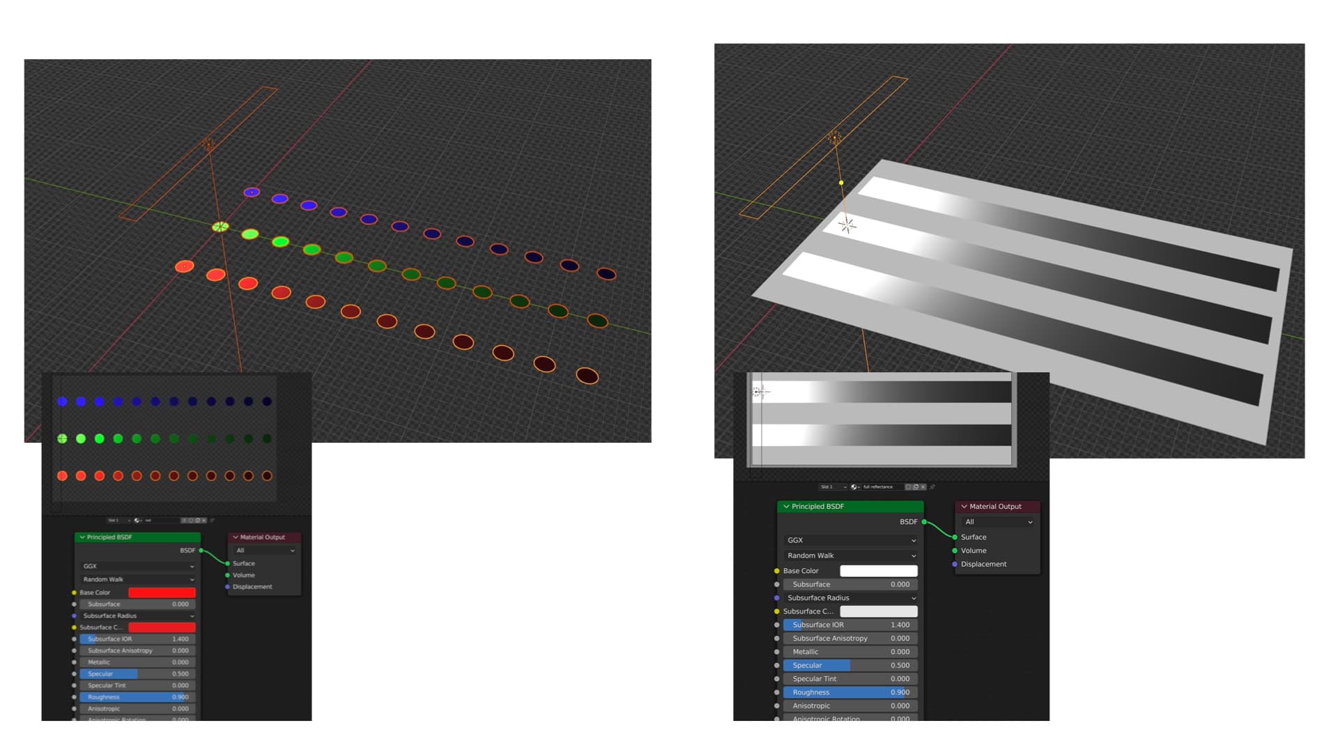
The idea is, if I got it right, that the coloured dots receive the same amount of light energy as the white stripes below. The dots reflect only in one channel each and absorb the other two. So no matter which viewing pipeline you see the merged result of the two render layers, the coloured dots should not have a higher emission value than the white stripes at the same horizontal position.

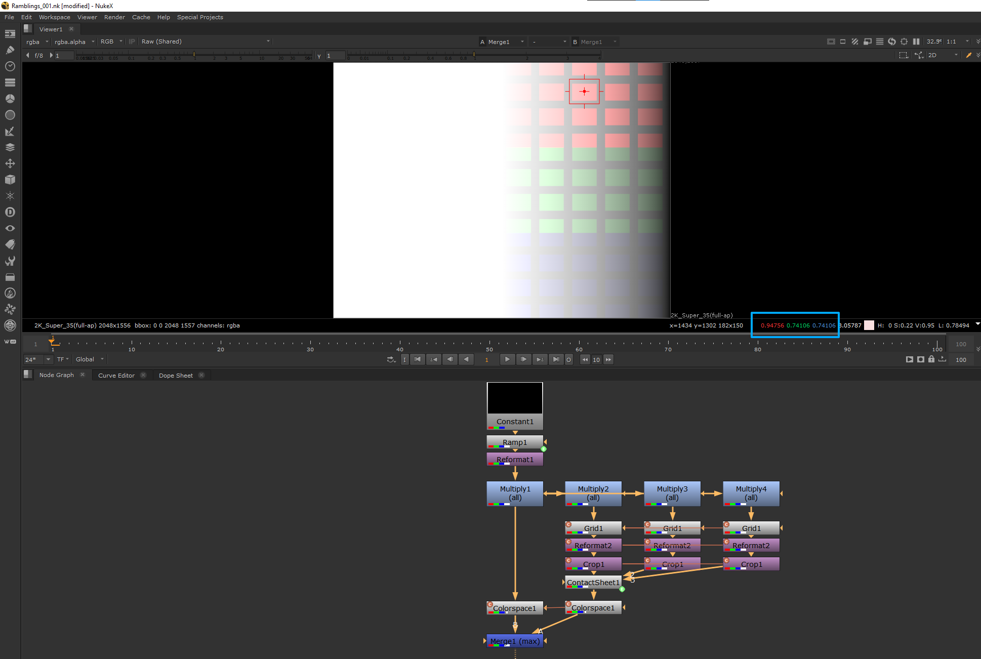
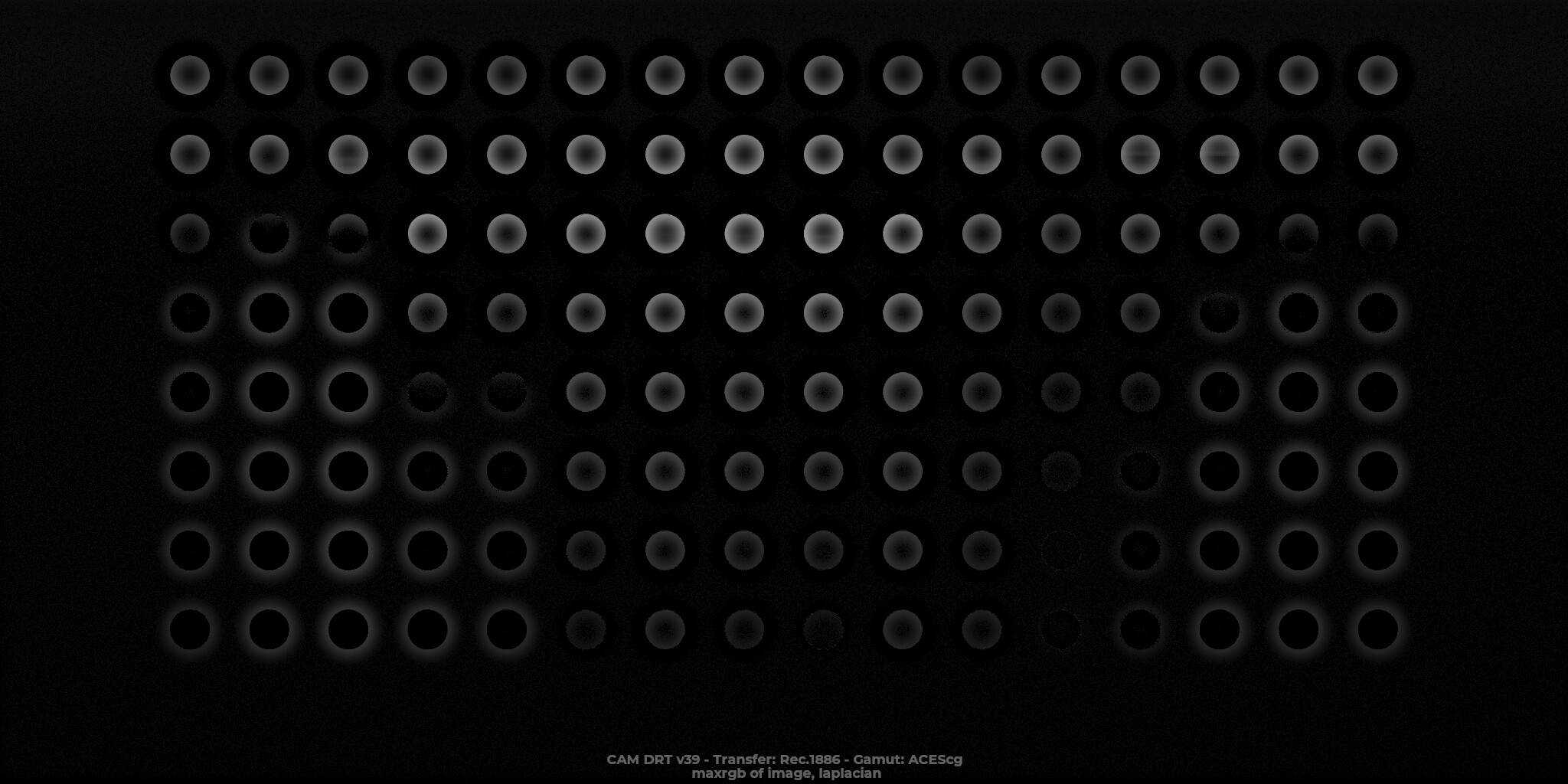
To check the results easier, the idea is to merge (max) the dots and the stripes layer after the ODT, DRT, etc.

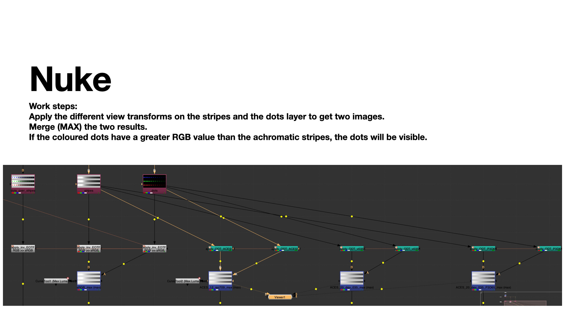
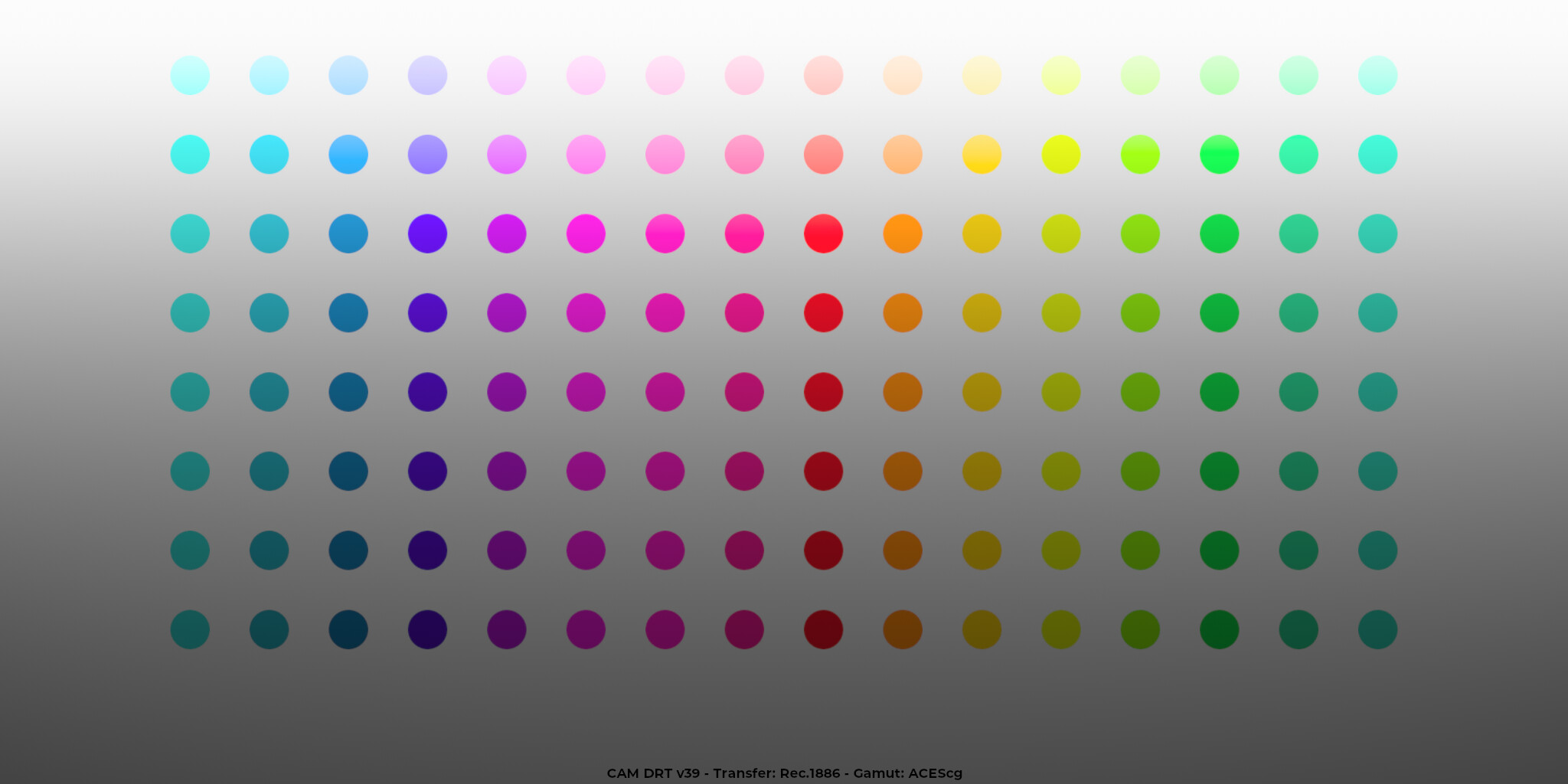
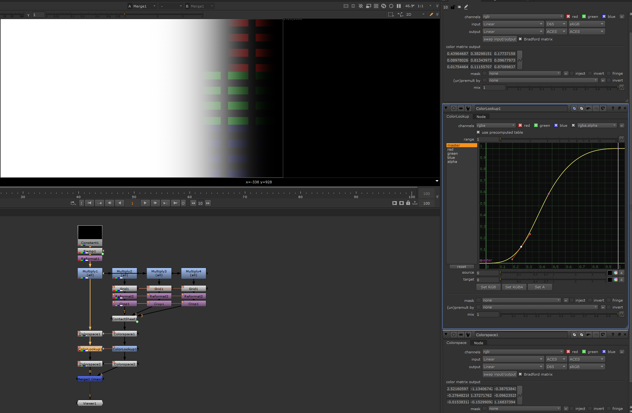
With the standard Nuke pipeline the merge (max) operation results only in the white stripes as expected. Next I tried two versions of AgX, T-Cam, ACES 1.2 Rec.709 and ACES 2.0 dev028 and dev035 in Rec.709 and P3D65.


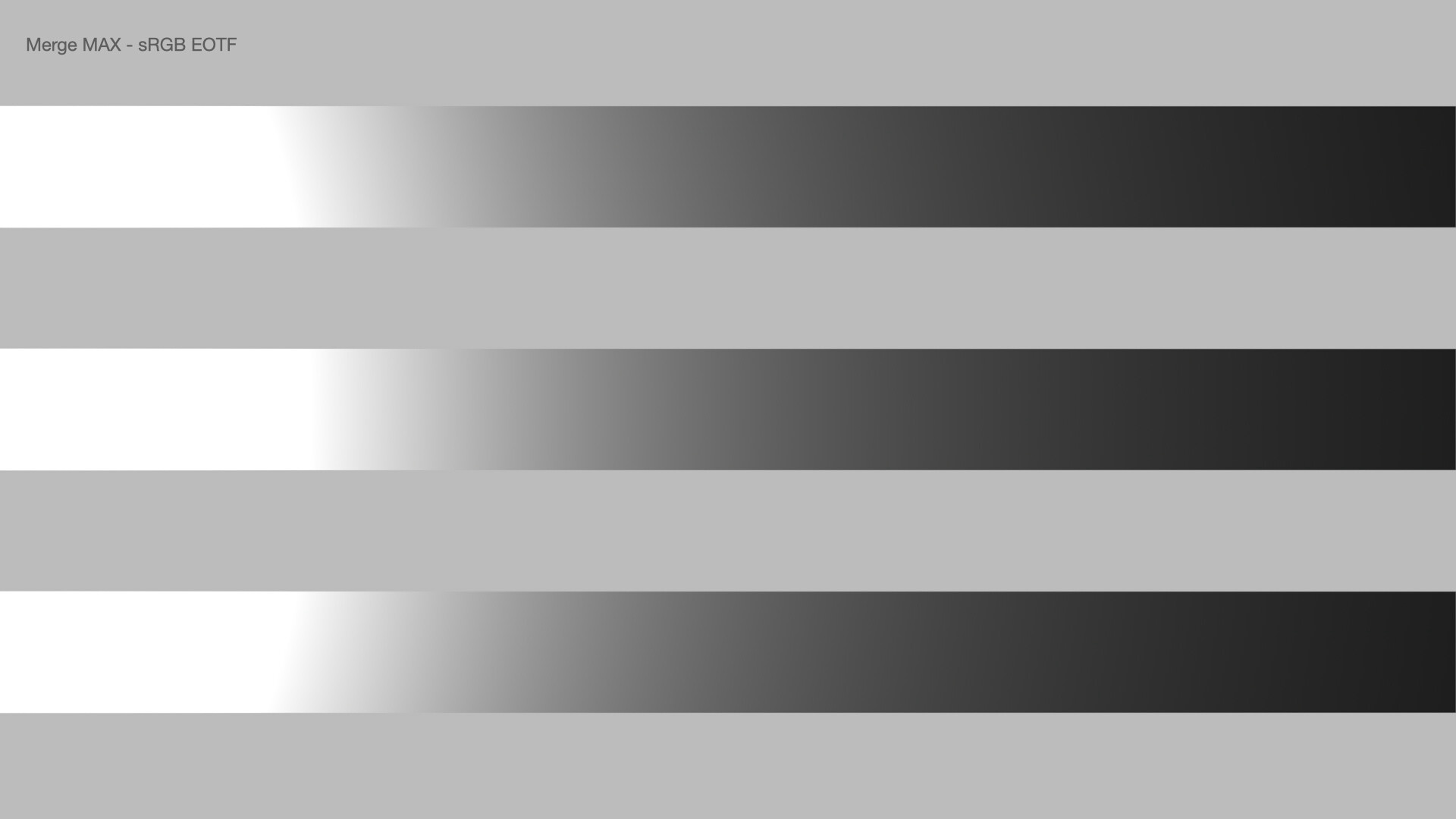
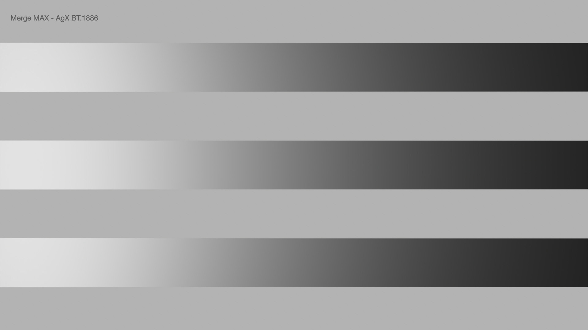
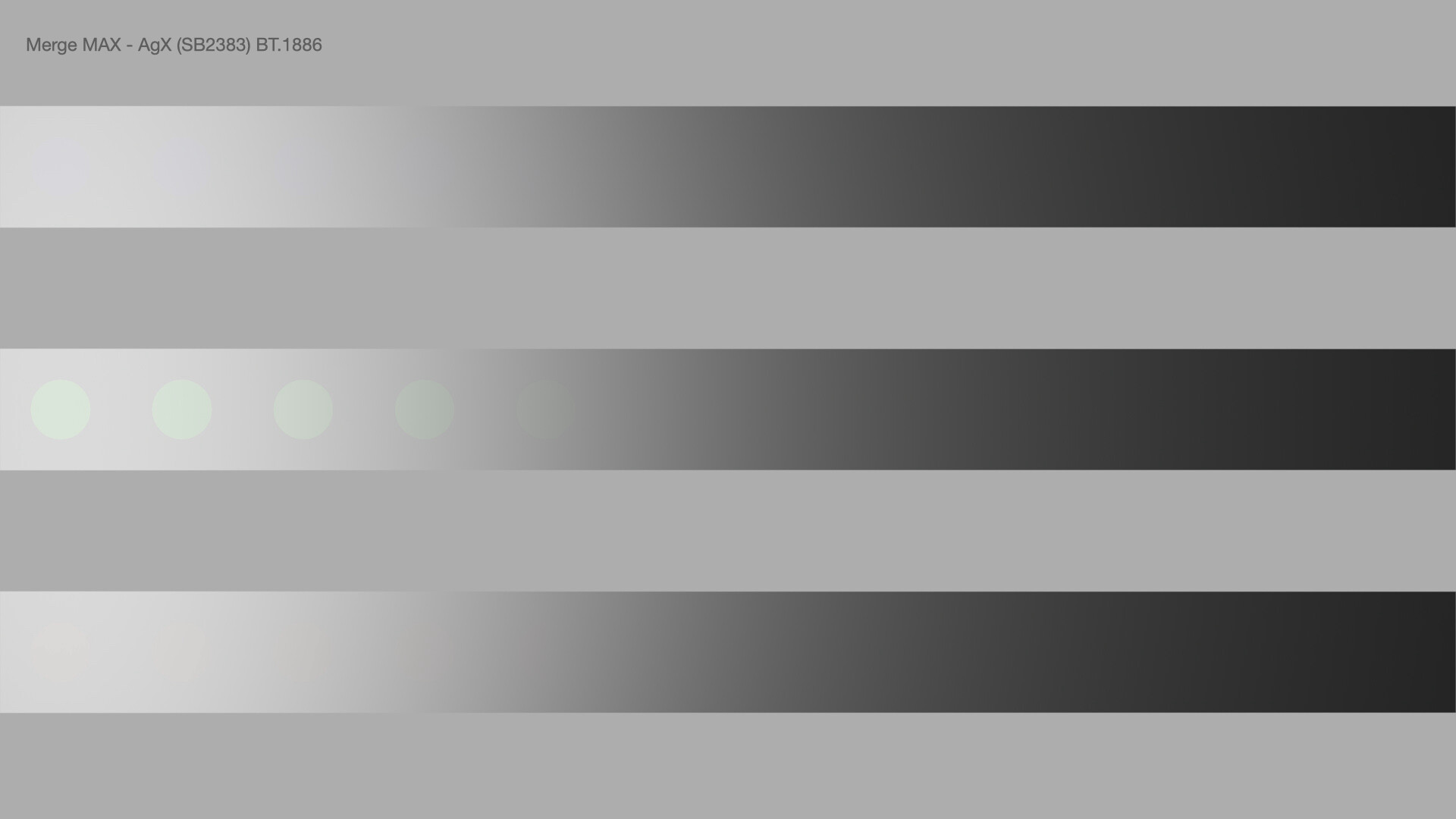
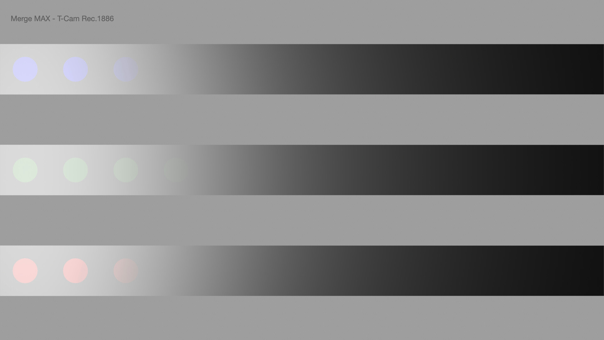
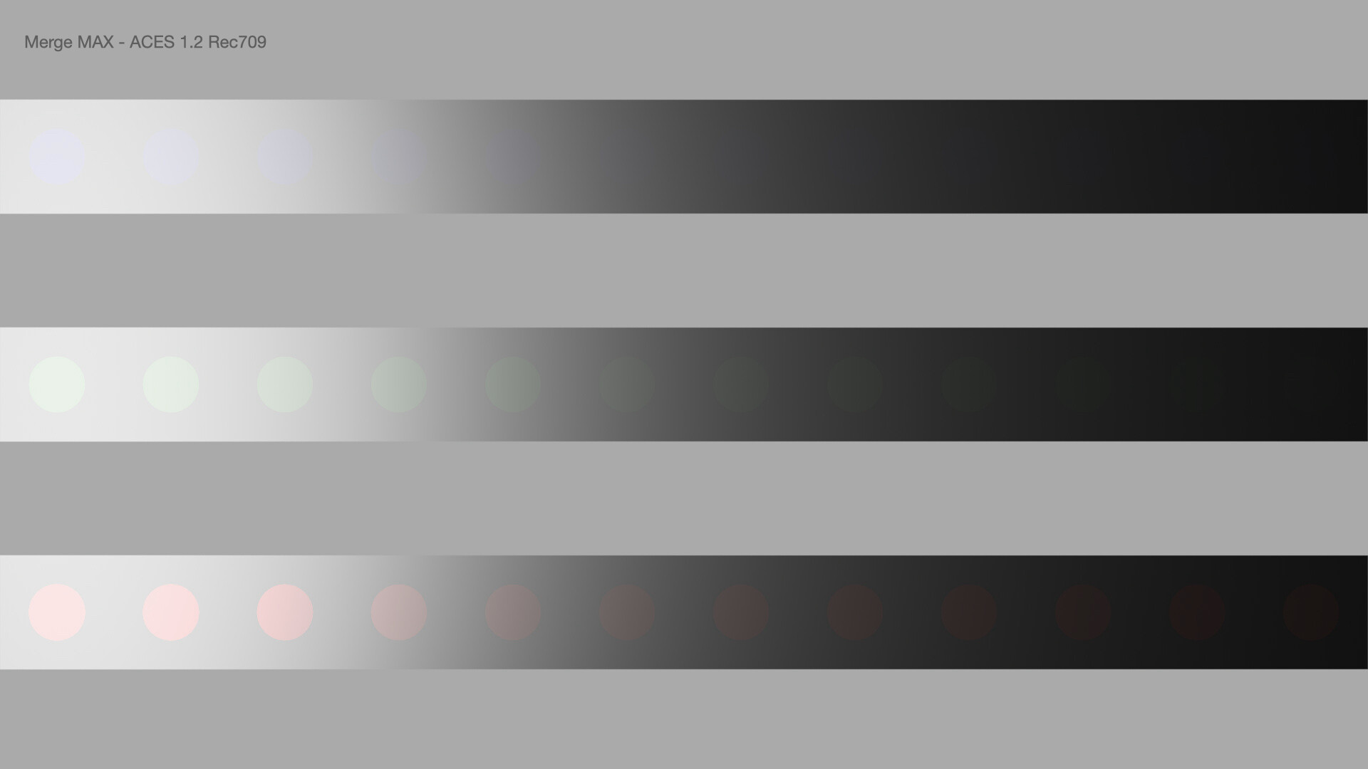
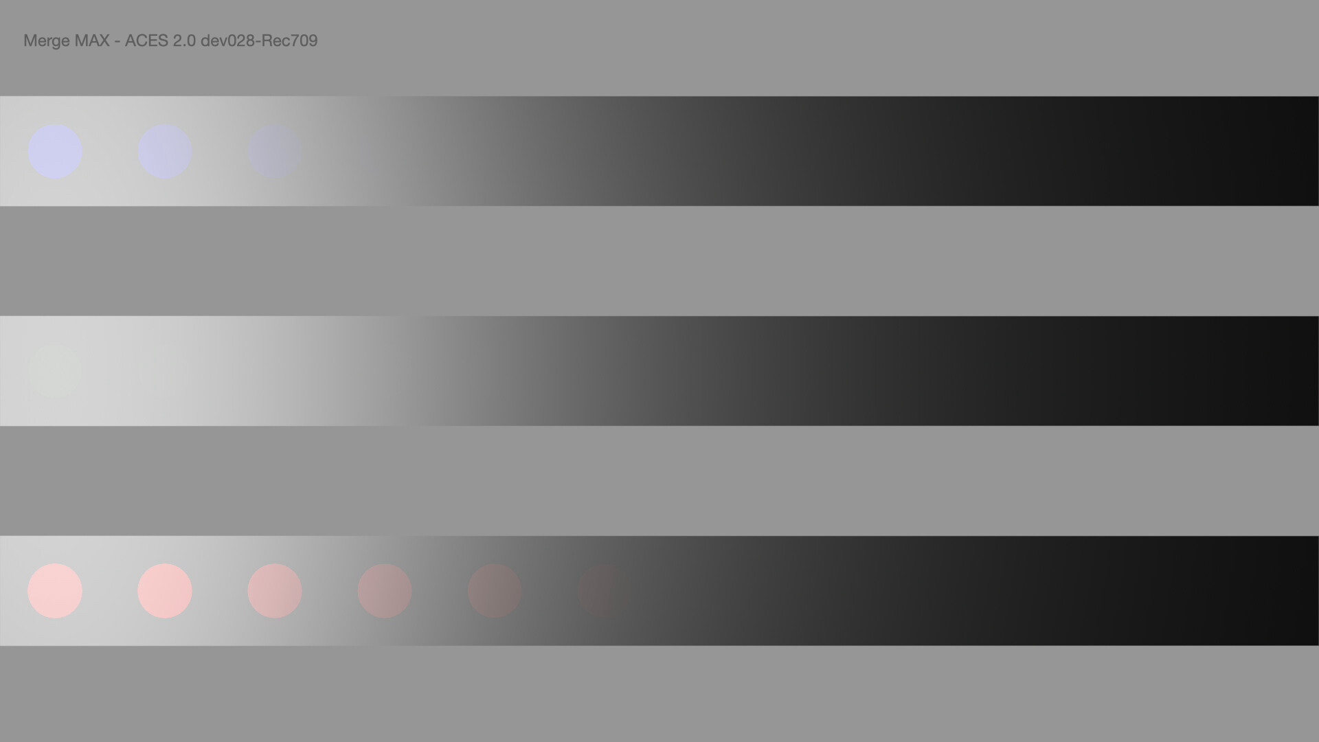
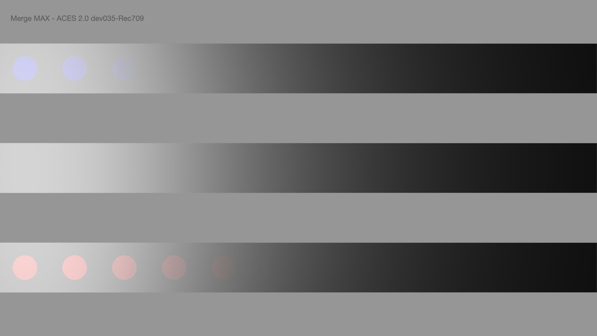
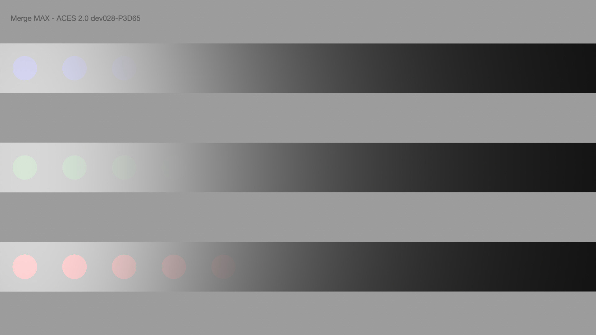
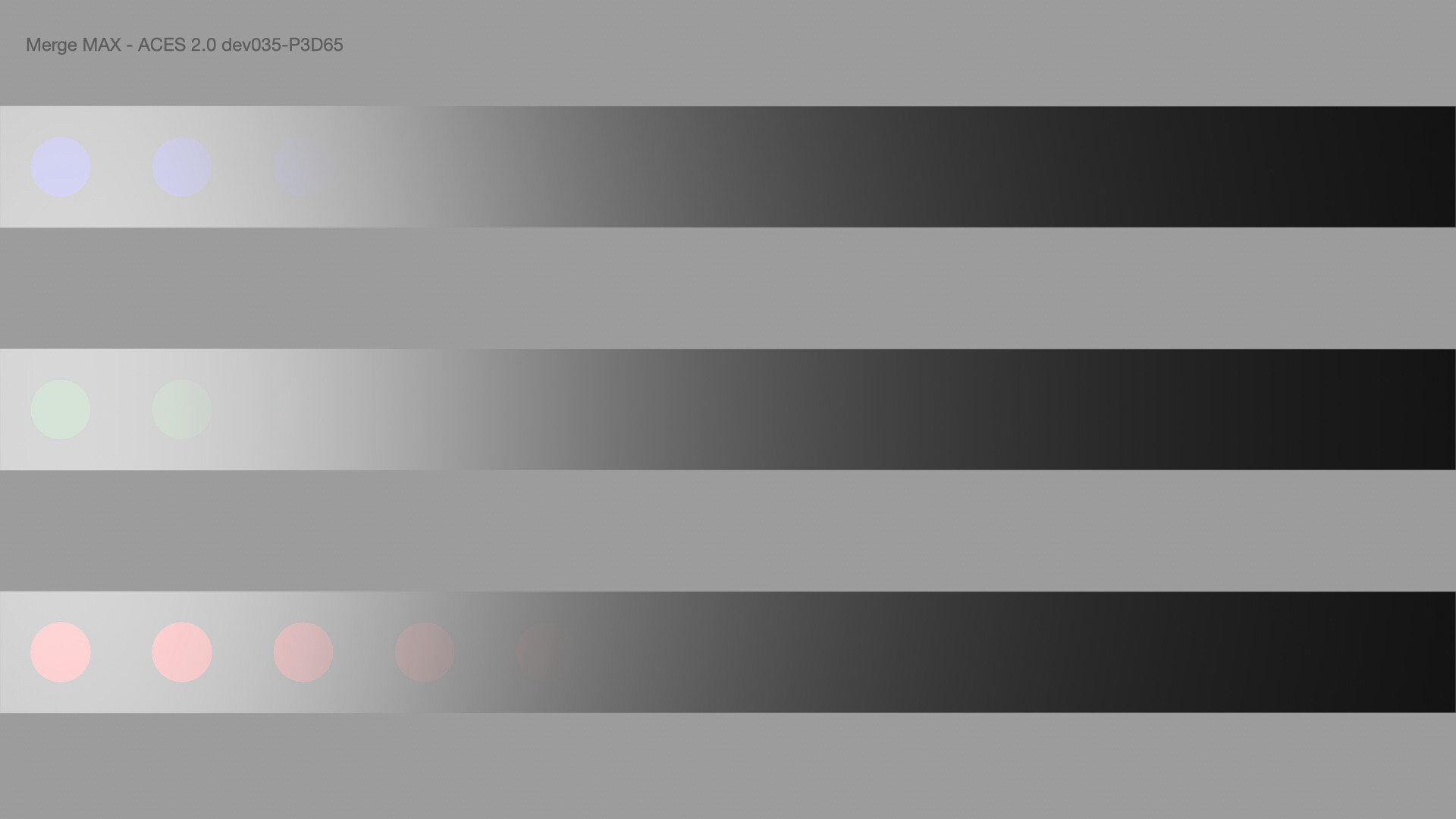
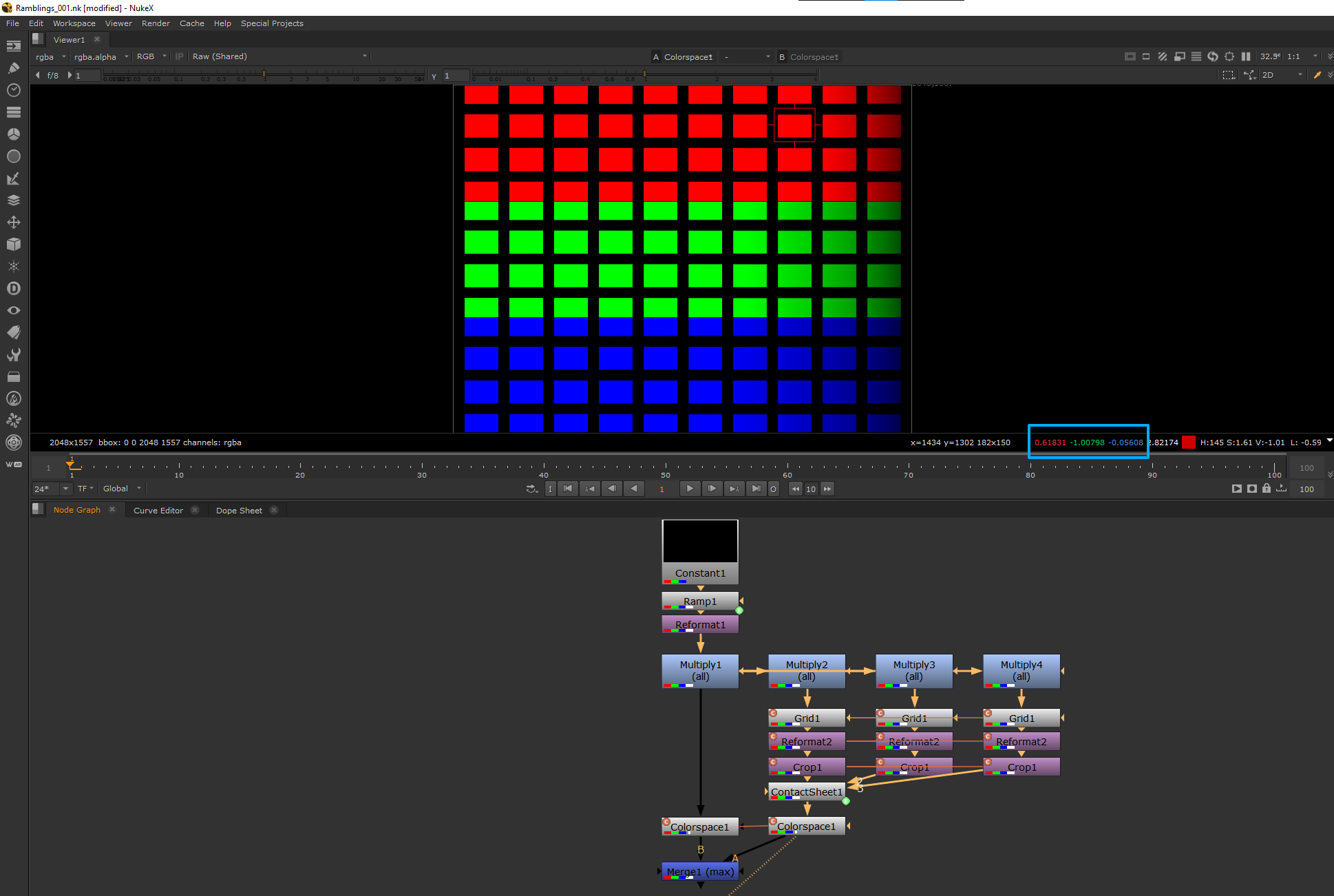
The results show that different viewing pipelines “render” the coloured dots with a higher RGB value than the white stripe below. But in the source blender render scene the stripes and the dots received equal energy.
I think it is interesting to inspect, but maybe someone can share some thoughts about why this happens and what it means in general.

(I exported the images out of a keynote document, that’s why the Jpeg uploads are all tagged DisplayP3. The original files that I dropped into the document are sRGB and P3.)

Here is the EXR multipass file:
https://my.hidrive.com/lnk/FZUrl4Sh

Best, Daniel

1 Like

Daniel,

So what you are presenting is that the dots and stripes are equal energy before rendering and unequal after dependent on the model used? So would that not suggest that the R, G, & B values derived from whatever coordinate system in the model used do not add up properly to give white/grey?

Also, how is the energy being measured? math?, photometer?, eye?

Also, are we to assume that equal energy of one spectrum of light will be the same as that of another spectrum?.. or further appear the same? So should the dots even look the same as the bars when they reflect different spectrum even though at the same energy? (Maybe so if the measuring device has exact flat spectral sensitivity.)

But even so, keeping a relative approach there still would seem indicated a difference between models and perhaps an indication that models may not be working as expected.

Hello,

I haven’t put too much thoughts into this as I’m not sure what is the intent? Are we trying to show something akin to a lack of energy conservation? Here is an observation on the method though: max only shows the excess per-channel but not the lack.

Given a very simple basis change and non-linear encoding (not required but is a bit closer to your test) from ACES2065-1 to Encoded sRGB, take a look at the blue boxes and especially the other two components for a given channel:

set cut_paste_input [stack 0]
version 13.2 v3
Constant {
 inputs 0
 channels rgb
 format "1920 1080 0 0 1920 1080 1 HD_1080"
 name Constant1
 selected true
 xpos -40
 ypos -268
}
Ramp {
 p0 {0 0}
 p1 {{width} 0}
 name Ramp1
 selected true
 xpos -40
 ypos -194
}
Reformat {
 flop true
 name Reformat1
 selected true
 xpos -40
 ypos -170
}
Multiply {
 value 2
 name Multiply1
 selected true
 xpos -40
 ypos -130
}
set N61819400 [stack 0]
Multiply {
 value {0 0 1 10}
 name Multiply4
 selected true
 xpos 290
 ypos -130
}
clone node2155d3cf000|Grid|23364 Grid {
 size 50
 color 0
 name Grid1
 selected true
 xpos 290
 ypos -74
}
set C5d3cf000 [stack 0]
clone node21595b5a000|Reformat|23364 Reformat {
 type scale
 scale {1 0.3333333333}
 name Reformat2
 selected true
 xpos 290
 ypos -50
}
set C95b5a000 [stack 0]
clone node21530c28000|Crop|23364 Crop {
 box {0 0 2048 519}
 name Crop1
 selected true
 xpos 290
 ypos -24
}
set C30c28000 [stack 0]
push $N61819400
Multiply {
 value {0 1 0 10}
 name Multiply3
 selected true
 xpos 180
 ypos -130
}
clone $C5d3cf000 {
 xpos 180
 ypos -74
 selected true
}
clone $C95b5a000 {
 xpos 180
 ypos -50
 selected true
}
clone $C30c28000 {
 xpos 180
 ypos -24
 selected true
}
push $N61819400
Multiply {
 value {1 0 0 10}
 name Multiply2
 selected true
 xpos 70
 ypos -130
}
clone $C5d3cf000 {
 xpos 70
 ypos -74
 selected true
}
clone $C95b5a000 {
 xpos 70
 ypos -50
 selected true
}
clone $C30c28000 {
 xpos 70
 ypos -24
 selected true
}
ContactSheet {
 inputs 3
 width {{width}}
 height {{"height * 3"}}
 columns 1
 roworder TopBottom
 name ContactSheet1
 selected true
 xpos 70
 ypos 2
}
clone node2155c7ad400|Colorspace|23364 Colorspace {
 illuminant_in ACES
 primary_in ACES
 colorspace_out sRGB
 bradford_matrix true
 name Colorspace1
 selected true
 xpos 70
 ypos 37
}
set C5c7ad400 [stack 0]
set N5ced1800 [stack 0]
push $N61819400
clone $C5c7ad400 {
 xpos -40
 ypos 38
 selected true
}
Merge2 {
 inputs 2
 operation max
 name Merge1
 selected true
 xpos -40
 ypos 84
}
push $N5ced1800
Viewer {
 frame 1
 frame_range 1-100
 colour_sample_bbox {0.400390625 0.51171875 0.578125 0.658203125}
 gl_buffer_depth float
 useGPUForViewer true
 useGPUForInputs true
 viewerProcess "Raw (Shared)"
 name Viewer1
 selected true
 xpos -40
 ypos 135
}

Now, ACES 1 & 2 and TCAM DRT do rendering in a different basis than that of the input space, so the above result is not really surprising.

Cheers,

Thomas

1 Like

This doesn’t make any sense.

At a (overly simplistic) neurophysiological level, there are combinatorial On-Off and Off-On differential cells. When the field is “equal”, the signal is a “null”. There’s a pretty solid amount of research to suggest that this polarity is of tremendous importance in the heuristics of visual cognition. From the null, the dynamic is either “up” or “down”, where we can make a direct line from the “down” polarity to being broadly correlated to reflectance.

Here’s a riff on the Briggs demonstration in achromatic to showcase the articulation fields.

One does not have to accept the claim outright, but simply examine the formed pictures and evaluate where fields of “uncanny” pop out. It has a direct relationship to this polarity dynamic. And of course, every single one of these bogus CAMs, which are nothing more than glorified luminance-devoid-of-chrominance “mappers”, cause this very polarity problem.

Any reasonable person can cognize the uncanny bridge being crossed. Compare the picture formation of the endless CAM attempts with the Laplacian evaluation, that showcases the polarity issues rather elegantly.


Take a close look at how all of these bogus CAMs amount to nothing more than a crappy luminance mapper, and how uncannily similar they are to the projection below. I can say “Crappy Luminance Mapper” because I wrote one from scratch and didn’t have to fit it to nonsense “research”:

See that mountain range? That’s a ridiculous luminance-devoid-chrominance map. See the same clefts that manifest in literally all of these bogus CAM models?

If one notes the achromatic strip in this bogus variation of my creation, one will note that the max(RGB) trick holds true here too.

Remember, research going very far back has already solved the chromatic strength of chromaticity angles for the global frame. This is an already solved problem. The problem these bogus Cartesian models are attempting to solve is already solved, and cannot be solved without considering the articulation field.

It should then come as no surprise that creative colour film was not a CAM. It was a basic, balanced to stasis model… Just like RGB, with the added wonderful density axis.

Beyond all of these “Colour Appearance Models” and “Uniform Colour Spaces” being nothing more than delusional nonsense, with specific respect to picture formation, they are the defacto cause of the polarity problem.

Again, and I cannot stress this enough, creative colour film was a basic balanced model. No really. And creative colour film continues to shame every one of these digital shibboleths.

image

1 Like

Why are you bringing colour appearance here when it is easy to show that a simple RGB colourspace transformation produces the same effect? What is the intent of the demonstration?

Given a RGB cube, transformed to another space, are you expecting that its boundaries/edges are “magically” vanishing?

What?

The picture formation — the part of the stage that is creating the colourimetry that we are looking at — is what is responsible here. A pure RGB per channel mapping does not produce this. Ever.

If one takes all “in gamut” values and forms pictures via a per channel mechanic, the foundational mechanic in forming the picture insulates against the polarity swings. Polarity swings are effectively what amount to errors:

  • Clips and any number of other “colourimetric” issues.
  • Bad Ideas such as CAMs or “Uniform Colour Models”.

When we parse a picture, we aren’t pretending we are standing there looking at a “scene”. In the assemblage of “cues” or “clues” that emerge out of the soup, some cues are powerful. By “powerful”, we can identify neurophysiological effects that cannot be overcome, as per Kingdom’s “rivalrous” demonstration:

The essence of something like HKE is likely a straight line path to these constellations of LGN field clusters of ON-OFF and OFF-ON responses, and the “polarity” that emerges. The delusional Cartesian “CAMs” and “UCS” are one of the reasons these polarity swings are being introduced in the formed pictures in the first place.

If one samples the polarities of generic RGB rendering, in the working space, the polarity is indicative of one direction. After the picture formation, the polarities have inverted in many cases. This is very plausibly a Bad Thing.

At the very least, most reasonable folks can look at the discs and literally visualize where the formed picture colourimetry is shredding apart, jumping “out” of the surface of the picture in many cases.


The peculiar “lustre” on those discs, is directly tied to what we can ontologize as the “twin” / “triple” (x2 for ON-OFF and OFF-ON chains at the very least) “chrominance-luminance” channels of the ON-OFF and OFF-ON cluster differentials. The greater the field differentials, the greater the “lustre” effect. The Laplacian analysis is far from a fluke.

It at least seems reasonable, then, that whatever magic soup one applies during the picture formation stage of imbuing meaning into the marks, that the underlying polarity should not be inverted. That is, if we compare the formed camera colourimetry or render colourimetry to the colourimetry in the formed pictures, a reasonable baseline is that the polarity should not invert.

Does that sound like what I am communicating? I honestly don’t even know how to reply to this.

The discussion is precisely about the polarity of the field relationships. The point of the analysis is not about determining what our ontologizing of “edge” is in a quantifiable sense, but rather the polarity and the polarity role in meaning.

TL;DR: It’s pretty reasonable to suggest that having polarity flip flop between the formed colourimetry of the camera data blob and the final, functional formed picture colourimetry, is a driving force in “HKE”, and is the Bad Thing that is leading to the “uncanny lustre”. Where the polarity is close to a null, the effect is lower than the sharper differentials. We can attribute polarity flip flops to:

  • Errors of colourimetric handling introduced at various stages of the chain.
  • Use of mythical “Colour Appearance Models” and / or “Uniform Colour Spaces”.

The latter is more relevant here, as that’s is what is forcing the polarity flip flops because the “models” are janky pantsed.

The “uncanny lustre” probability increases as the field differentials diverge, as can be visualized by these samples:


1 Like

Since there is a deadline for the development now, I’m worried even more, that this artifact will stay in the final version. As a user, I can somewhat (per-channel) deal with the tone scale, yet it seems to take a lot more development time than, for example, this artifact, that, in my opinion, is way more important for the end users. Because users can’t fix this by themselves. With old per-channel tone mapping users at least know what to do when the sky has different hue in HDR vs SDR. But now it’s like solving the issue that we can solve on our end, but adding a new one, that we can nothing to do to fix.

I guess this isn’t going to be the final final version forever. So maybe, until the very wide gamut and bright displays become a thing, we could use something that is not so future-proof parametric, but instead just a simple DRT, that, what’s most important, looks smooth with various gradients?
I’d even be happy with per-channel approach, maybe with some out of the box hue fixes for HDR vs SDR outputs.

I know that a lot of users want ACES 2 DRT to be hue preserving for HDR vs SDR. But I’m sure survey results would be different if the question was to choose one:

  1. It preserves hue for different brightness and it’s parametric in case of the new technologies that are not here yet, but you can’t use it with defocused LEDs and maybe even with defocused stained glass in the image.

  2. It is not hue preserving, but we ship it with the tweaks for HDR vs SDR, that kind of help you with this. Also it doesn’t preserve out-of-working-gamut colors well, just clips it (as any DRT LUT you always use and love). But you can easily and intuitively reach the corners and the gradients will stay smooth whatever you do.

2 Likes

It seems like that you did not read what I wrote:

I’m in fact actually talking about the rendering and it is trivial to show that per-channel RGB rendering does produce what @TooDee is reporting and that you are incorrect. CAMs, Perceptually Uniform Colourspaces, put the flavour of the day, are not, fundamentally the cause, the change of basis is!

Here is a better example, starting from ACES2065-1, per-channel RGB rendering in sRGB and back to ACES2065-1, flip it the desired way and it will still produce similar results:

set cut_paste_input [stack 0]
version 13.2 v3
Constant {
 inputs 0
 channels rgb
 format "1920 1080 0 0 1920 1080 1 HD_1080"
 name Constant1
 selected true
 xpos -40
 ypos -274
}
Ramp {
 p0 {0 0}
 p1 {{width} 0}
 name Ramp1
 selected true
 xpos -40
 ypos -202
}
Reformat {
 type scale
 flop true
 name Reformat1
 selected true
 xpos -40
 ypos -178
}
Multiply {
 value 2
 name Multiply1
 selected true
 xpos -40
 ypos -138
}
set N61819400 [stack 0]
Multiply {
 value {0 0 1 10}
 name Multiply4
 selected true
 xpos 290
 ypos -138
}
clone node2155d3cf000|Grid|23364 Grid {
 size 50
 color 0
 name Grid1
 selected true
 xpos 290
 ypos -82
}
set C5d3cf000 [stack 0]
clone node21595b5bc00|Reformat|23364 Reformat {
 type scale
 scale {1 0.3333333333}
 name Reformat2
 selected true
 xpos 290
 ypos -58
}
set C95b5bc00 [stack 0]
clone node21530c28000|Crop|23364 Crop {
 box {0 0 2048 519}
 name Crop1
 selected true
 xpos 290
 ypos -34
}
set C30c28000 [stack 0]
push $N61819400
Multiply {
 value {0 1 0 10}
 name Multiply3
 selected true
 xpos 180
 ypos -138
}
clone $C5d3cf000 {
 xpos 180
 ypos -82
 selected true
}
clone $C95b5bc00 {
 xpos 180
 ypos -58
 selected true
}
clone $C30c28000 {
 xpos 180
 ypos -34
 selected true
}
push $N61819400
Multiply {
 value {1 0 0 10}
 name Multiply2
 selected true
 xpos 70
 ypos -138
}
clone $C5d3cf000 {
 xpos 70
 ypos -82
 selected true
}
clone $C95b5bc00 {
 xpos 70
 ypos -58
 selected true
}
clone $C30c28000 {
 xpos 70
 ypos -34
 selected true
}
ContactSheet {
 inputs 3
 width {{width}}
 height {{"height * 3"}}
 columns 1
 roworder TopBottom
 name ContactSheet1
 selected true
 xpos 70
 ypos 14
}
clone node2155c7ad400|Colorspace|23364 Colorspace {
 illuminant_in ACES
 primary_in ACES
 bradford_matrix true
 name Colorspace1
 selected true
 xpos 70
 ypos 62
}
set C5c7ad400 [stack 0]
clone node215d5477c00|ColorLookup|23364 ColorLookup {
 lut {master {curve C 0 x0.2659826875 0.1438275576 x0.4750539064 0.6065092087 x1 1 s0}
   red {}
   green {}
   blue {}
   alpha {}}
 name ColorLookup1
 selected true
 xpos 70
 ypos 110
}
set Cd5477c00 [stack 0]
clone node215c6e86000|Colorspace|23364 Colorspace {
 illuminant_out ACES
 primary_out ACES
 bradford_matrix true
 name Colorspace2
 selected true
 xpos 70
 ypos 158
}
set Cc6e86000 [stack 0]
push $N61819400
clone $C5c7ad400 {
 xpos -40
 ypos 62
 selected true
}
clone $Cd5477c00 {
 xpos -40
 ypos 110
 selected true
}
clone $Cc6e86000 {
 xpos -40
 ypos 158
 selected true
}
Merge2 {
 inputs 2
 operation max
 name Merge1
 selected true
 xpos -40
 ypos 206
}
Viewer {
 frame 1
 frame_range 1-100
 colour_sample_bbox {1.356250048 0.4187499881 1.357291698 0.4197916687}
 gl_buffer_depth float
 useGPUForViewer true
 useGPUForInputs true
 viewerProcess "Raw (Shared)"
 name Viewer1
 selected true
 xpos -40
 ypos 283
}

max simply does not tell the full story. ACES 1.x which is purely per-channel RGB rendering exhibits the same behaviour which @TooDee verified above.

Cheers,

Thomas

Hi @meleshkevich ,

it’s the second time that you post the neon sign image after a post of a rather abstract example.
I think the last time you posted this image after I posted a row of images with the three red, green and blue spheres a while back where I wondered about the “color” shifts in different renderings.

I wonder in which way the fringe on the neon sign is related to the post that I did, the ones from @Thomas_Mansencal and the ones from @Troy_James_Sobotka. I have a feeling the the issues are related but I cannot explain why.

Hi! If I understand it right, this sharp blue line in the gradient comes from inconsistent brightness of the blue color. But I posted it because of the notes (thank you for making them, @nick !)
from the latest meeting, where I’ve read about the deadline for the development.

1 Like

Yes, this is how I understand this example/demonstration. I learned not long ago that the ratio of whatever initial/ source rgb values are always changing when converting to another colourspace. (https://www.toodee.de/?page_id=5927)

simply r, g and b values? These are the values that I work in Nuke with.

Max does tell the full story when we are dealing with valid domain values. max(RGB) is the achromatic centroid. max(RGB) can be considered the bridging linkage of “energy” to “neurophysiological signal” in the combined chrominance and luminance sense, where chrominance also has a polarity. (From a technical vantage, so does luminance.)

What I would suggest is to try any basic luminance mapper and pretend it’s a CAM, because that’s what they amount to. Then try a basic channel by channel mapping using a classic monotonic curve. What will become evident, without bringing point 1. that I tried to make clear regarding colourimetry fuckery, is that the per channel will never violate polarity. And a basic luminance mapper will.

So please try to set aside the nonsense of “colourimetric transformations” for a moment, and think purely about “legal” stimulus quantities.

TL;DR: A luminance-without-chrominance “CAM” will always yield polarity flip flops. Which as a corollary, would be the equivalent of a surface generating more energy in a PBR system. It follows that more energy will generate a greater neurophysiological signal along luminance or chrominance, or both.

It might seem like a reach, but the best I can advise is to try it. One can use any working colourimetric “colourspace” for the analysis, as long as we don’t introduce “gamut mapping” by way of a 3x3 or otherwise into the calculation.

Confidence or evidence? The basic Nuke script above demonstrates the behaviour.

So you are now acknowledging that the basis change does indeed produce the reported behaviour?

Evidence. Try it.

Read the post. Read the first bullet point. Don’t forget that there was someone talking about basis vectors and the fact that only IE has a conservation of total scaling energy a long time ago.

Again, don’t get distracted from the point I’m trying to make:

CAMs and UCS are nothing more than luminance based mappings, devoid of chrominance. As such, they will introduce these polarity errors.

1 Like

I think what @Troy_James_Sobotka is trying to say is, while it appears that Opponent Spaces (and all their derived scales) give you more degree of freedom (modifying A Vs not touching B) in reality those edits can produce unwanted folds and other unpleasant effects in the corresponding RGB data.
He tries to formulate a sensible constrain to what you can do with those individual scales.

From my experience with working in different colour models with real images he is absolutely right.
The degree of freedom in those spaces is actually not as big as you wish. They are seductive, and pretend to give you easier control while hiding potential drawbacks.

In the end all those models only predict the data they were fit against. None of those data sets actually resemble what we are doing here.

I disagree with his categorical rejection of the utility of appropriated models, while admitting that none of the “fit against data” models seem to work out of the box for this use case.

I admire though that he tries to construct a route from first principles. I hope he succeeds. (And I hope we have a framework to plug his work in - once it is working).

8 Likes

I certainly don’t disagree, my point was that rendering in different spaces (even RGB) produces different results and that it is enough to create what @TooDee was showing.

We were talking about that stuff with Steve Agland (who pointed out the issue), Zap Anderson, Rick Sayre, Anders Langlands, HPD and a bunch of other people on 3D-Pro back in 2014. That was in the context of CG rendering but it applies here and everywhere else.

With that in mind (and where I was going to) is that a common rendering space (irrespective of what that space is) is highly desirable because this is the only way to ensure that an image appears the same on different displays.

Cheers,

Thomas

2 Likes

ok,

I understand now that creating a 3D render in one working colourspace (e.g. linear Rec.709) will change some of its original meaning (e.g. base “color” shader value/settings)when doing the comp in ACEScg as an example.
The ratio between the three channels red, green and blue are changing with a colorspace transform.

So I could repeat the tests that I did and assign ACEScg primaries for the ACES tests, E-Gamut primaries for the T-Cam test etc.
Would the test showing then more useful results than now?

Thanks,

Daniel

Stop with this revisionist history nonsense.

Not a single soul was discussing polarity. Where are you making this stuff up?

It has nothing to do with the complements channels and other rendering facets. Nothing at all to do with polarity of On-Off / Off-On.

Mythical fictions.

More mythical fiction and quite a claim of “appear the same”.

Try parsing what is being said before mashing the keyboard.

1 Like

You are impossible and I’m reading you well don’t worry.

Let me summarise for you: If you read the OP, images were presented showing a behaviour and seeking for explanation as to why or the meaning of it:

What I did is showing that a basis change, a simple 3x3 matrix, causes that. Again, the ACES 1.x DRT does the same and it is RGB rendering. No need to go down the rabbit hole or 4-dimensional chess game to find an explanation.

Fiction? How so? We do exhibit images that have been rendered in a common working space on different displays with different technologies, e.g. monitors, TV, LED wall. This is how we produce all our movies. We do that on a daily basis and I’m pretty sure that Framestore, ILM, DNeg and hundreds of vendors do the same.

String due to the community flagging the post as hateful conduct.

[quote=“Thomas Mansencal, post:19, topic:5161, username:Thomas_Mansencal”]
What I did is showing that a basis change, a simple 3x3 matrix, causes that. Again, the ACES 1.x DRT does the same and it is RGB rendering. No need to go down the rabbit hole or 4-dimensional chess game to find an explanation.
[/quote]

1. ACES is a terrific demonstration if one seeks to show that poor design doesn’t work. Nothing more.
2. Did one actually test the claim about per channel?

Here is the basic idea, again. Apologies, perhaps it’s a language barrier?

  1. Because of On/Off and Off/On neurophysiological signals, polarity matters, specifically at the “null”.
  2. The combined force of chrominance-luminance is a threshold, where luminance can be broadly correlated to the Protan+Deutan absorptive combination, and the remaining two signals are effectively (Protan+Deutan)-Tritan, and Protan-Deutan, in both On/Off and Off/On variations. (At risk of grotesque oversimplifications.)
  3. Per channel, devoid of colourimetric transforms, does not induce a polarity flip.

It is perfectly fine to reject the first point, which dismisses all subsequent points.

However, if anyone detects the same cognitive “oddness”, then the premise might hold veracity. Note this is the same general premise that Briggs covers in a video if one wants to see a live demonstration.

Note I am not 100% confident the max(RGB) is “the” threshold, but I’m leaning toward it being the combined neurophysiological force that correlates with the combined force of chrominance and luminance. I believe this can be shown mathematically as well.

Now, again, if the premise of polarity playing a foundational role in visual cognition, then it can be shown that:

  1. Per channel mechanics devoid of colourimetric transforms will not exhibit this. This can be tested.
  2. Colourimetric transforms, by way of a 3x3 matrix can and will exhibit polarity flips.
  3. All of these glorified luminance-devoid-of-chrominance-contribution mappers will induce a polarity exchange.

Again, folks are free to reject the polarity issue outright. That’s fine. However, if there is a visual result that is indeed cognitively disruptive, then points 2 and 3 are valid concerns.

This isn’t “4 dimensional chess”. It’s actually very basic deductive reasoning by way of removing complexities.

A case in point, I would encourage anyone to distill and reduce the complexities by way of:

  1. Generate a PBR case where R=G=B at 100% albedo for an ideally reflective surface emulation.
  2. Set any chromatic textures to the discs that are biased in balance.
  3. Set the “diffuse source” close to the top of the surface, and render such that the upper most point is 1.0 units, to showcase a “gradation” of the model “light fall off”.
  4. Render using BT.709 or any working space such at BT.2020, without any colourimetric transforms.
  5. Apply a simple inverse EOTF to the values for display, or analyse the origin RGB tristimulus colourimetry.

It should reveal that no such polarity “flip” will result where the chromatic discs exceed the “illumination”. The same applies for any monotonic per channel curve.

In terms of visual cognition, zero of the swatch samples will “pop out”.

Again, and I stress, if folks want to reject the literature about polarity, they are free to do so. Move along. Carry on. Nothing to see here! No problem!

If folks have concerns about the polarity, it is worth understanding the various discrete signal processing positions that such polarity errors will manifest, and understand their causation.

The choice is up to the individual.

2 Likes