Hi I am new to this forum and looking for some advice on an upcoming project we are going to be working on. We normally work ACES internally for all projects even though not all are our projects are an ACES delivery. So for the most part its a hybrid system where we ingest material into ACES using the correct IDT’s for the cameras used and drop back to the shows native coloursapce to apply any cdl and display luts and go back to native on final delivery as and when required. All has been going swimmingly and made our whole colour pipeline much simpler.
One new project is being shot on film and it doesn’t look like its going to be scanned using ADX even though we have requested an ACES workflow so whats he best way to deal with this as we want to stay ACES internally . So far I believe they are using Cineon to linear curve and any display LUTS and colour ops are set to work in Cineon. Should I still use the ADX IDT to bring them into our internal working ACES colour space and work as I normally do in a hybrid manor going back to the original colour via inverse transform to apply colour ops and display for media back to them. It alls seems to match on a round trip back, but I am concerned this may cause some issues for any CG material that will be added to the shots as the inverse transform is going to ADX and not Cineon could this push things out of range? Or are we best to not work ACES and stick with native linear or use a different method to ingest. Any advice would be helpful.
It is but then you need to change the primaries as they are not ACES but in sRGB so additional transforms will be required. I have tried using Utility - Linear - sRGB but it doesn’t look right to me.
Yes currently experimenting. Ingest using ADX10, but then all the CDL’s are then applied back in original log. So we do a reverse transform back to ADX10 which puts it back to native Cineon then apply CDL then back to linear again within Nuke using OCIOFileTransform with a working space as log which is defined as ADX10 in the OCIO config . The Display is set up to do the same for the clients Film LUT or we can use the standard ACES Rec709 RRT/ODT. The latter is used to bake into any Quicktimes for them to review, so round trip is transparent.
So if I’m following you Read (IDT) is ADX [ADX to ACEScg] > invADX [ACEScg to ADX]. This would be a noOp, essentially the same as setting the Read node to raw. CDL processed in ADX (based on compositing_log role in OCIO).
I was thinking instead to use the REDLogFilm (=Cineon) curve instead of ADX all the way through, so you set the OCIO compositing_log role to REDLogFilm. Then injest (Read node) in REDLogFilm. That puts you in ACEScg working space. CDL is processed in log (which is Cineon i.e. REDLogFilm). Then apply client film LUT (also with REDLogFilm/Cineon process space) as ODT.
Sorry for late reply been on leave. Using this wont be putting the plates into ACES primaries its just the base Cineon linearisation curve without any colour adaption from what I understand. Any CG would be created in ACES so we would have two different primaries to deal with which is not ideal. I can add an sRGB to ACES conversion using Utility - Linear -sRGB but not sure if thats the best way of dealing with it. Using the Cineon curve I noticed that exposure is very different on the linear images especially noticeable when using ACES RRT/ODT compared to ADX10 which exposure wise matches more closely exposure wise to their supplied Film Emulation LUT.
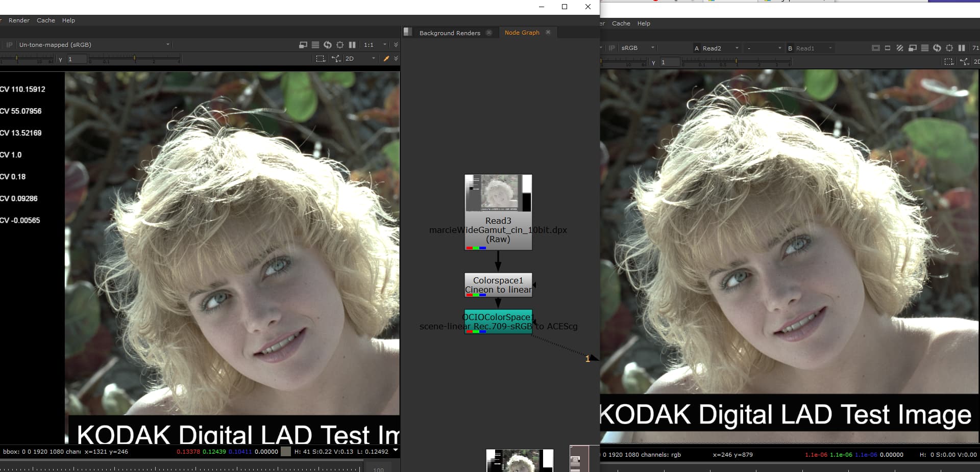
I did some testing in Nuke using KODAK’s Maricie as a DPX in cineon color space. On one side I have default Nuke with the read node set to Cineon and sRGB on the view transform.
On the other side I have Nuke with an ACES config, with the viewer in ACES set to un-tone-mapped to match Nuke’s default sRGB display.
I get a pretty good match when I set the ACES Read color space to ADX10. What gives me the best match (afaik it’s a perfect match) is setting the Read to Raw, then using a Nuke ColorSpace node in:cineon out: linear followed by OCIOcolorSpace in: linear_sRGB out: ACEScg.
I get the exact same result if I use CineonLog_to_linear.spi1d instead of the Nuke ColorSpace cineon to linear above. With that in mind here’s the whole thing as an OCIO color space:
The un-tone-mapped display is based on the display transform from the OCIOv2 demo config which uses the built-in transform. It’s an inv EOTF for an sRGB Display with D65 whitepoint.
I made a version of it for OCIOv1 using Jed Smith’s inverse EOTF Nuke script to create a LUT for OCIO. Here’s the Nuke script (copy-paste into Nuke)
set cut_paste_input [stack 0]
version 13.1 v1.013601b
push $cut_paste_input
Group {
 name InverseEOTF
 label "\[value eotf]"
 selected true
 xpos -192
 ypos 50
 addUserKnob {20 EOTF_tab l EOTF}
 addUserKnob {4 eotf t "Choose the inverse EOTF to apply for the target display device." M {None "sRGB Display" BT.1886 "Gamma 2.6" PQ HLG "" "" "" ""}}
 eotf "sRGB Display"
}
 Input {
  inputs 0
  name Input
  xpos 400
  ypos -160
 }
 Dot {
  name Dot1
  xpos 434
  ypos -96
 }
set N9838a800 [stack 0]
 Dot {
  name Dot3
  xpos 544
  ypos -96
 }
set N9838a400 [stack 0]
 Dot {
  name Dot4
  xpos 654
  ypos -96
 }
 Multiply {
  channels rgb
  value 10
  name Multiply1
  label "scale input 0.1x for 1000 nit match between PQ and HLG"
  xpos 620
  ypos -76
 }
 Expression {
  temp_name0 Yd
  temp_expr0 0.2627*r+0.6780*g+0.0593*b
  expr0 r*pow(Yd,(1-_g)/_g)
  expr1 g*pow(Yd,(1-_g)/_g)
  expr2 b*pow(Yd,(1-_g)/_g)
  name HLG_InverseOOTF
  xpos 620
  ypos -28
  addUserKnob {20 CONSTANTS_tab l CONSTANTS}
  addUserKnob {7 _g t "Gamma: Extended model for gamma variation according to peak display luminance and surround luminance: BT.2390-8 p32" R 0 2}
  _g {{1.2*pow(1.111,log(Lw/1000)/log(2))*pow(0.98,log(max(1e-6,Lamb)/5)/log(2))}}
  addUserKnob {7 Lw R 600 4000}
  Lw 1000
  addUserKnob {7 Lamb t "ambient luminance level in nits" R 0 200}
  Lamb 5
 }
 Expression {
  expr0 r<=1/12?sqrt(3*r):_a*log(12*r-_b)+_c
  expr1 g<=1/12?sqrt(3*g):_a*log(12*g-_b)+_c
  expr2 b<=1/12?sqrt(3*b):_a*log(12*b-_b)+_c
  name HLG_OETF
  selected true
  xpos 620
  ypos 5
  addUserKnob {20 CONSTANTS_tab l CONSTANTS}
  addUserKnob {7 _a t alpha}
  _a 0.17883277
  addUserKnob {7 _b t beta}
  _b {{1-4*_a}}
  addUserKnob {7 _c}
  _c {{0.5-_a*log(4*_a)}}
 }
push $N9838a400
 Expression {
  expr0 pow((c_1+c_2*pow(r*Lw/10000,m_1))/(1+c_3*pow(r*Lw/10000,m_1)),m_2)
  expr1 pow((c_1+c_2*pow(g*Lw/10000,m_1))/(1+c_3*pow(g*Lw/10000,m_1)),m_2)
  expr2 pow((c_1+c_2*pow(b*Lw/10000,m_1))/(1+c_3*pow(b*Lw/10000,m_1)),m_2)
  name ST2084_InverseEOTF
  xpos 510
  ypos -43
  addUserKnob {20 CONSTANTS_tab l CONSTANTS}
  addUserKnob {7 m_1}
  m_1 {{2610/4096*(1/4)}}
  addUserKnob {7 m_2}
  m_2 {{2523/4096*128}}
  addUserKnob {7 c_1}
  c_1 {{107/128}}
  addUserKnob {7 c_2}
  c_2 {{2413/128}}
  addUserKnob {7 c_3}
  c_3 {{2392/128}}
  addUserKnob {7 Lw t "Display peak luminance in nits" R 600 4000}
  Lw 10000
 }
push $N9838a800
 Expression {
  expr0 sign(r)*pow(fabs(r),1/p)
  expr1 sign(g)*pow(fabs(g),1/p)
  expr2 sign(b)*pow(fabs(b),1/p)
  name power
  xpos 400
  ypos -70
  addUserKnob {20 Params_tab l Params}
  addUserKnob {7 p l power R 0.2 2}
  p {{eotf?2+eotf*0.2:1}}
 }
 Switch {
  inputs 3
  which {{max(0,eotf-3)}}
  name SwitchInverseEOTF
  xpos 400
  ypos 5
 }
 Output {
  name Output
  xpos 400
  ypos 80
 }
end_group
It’s intent is for diagnostic purposes. In this case getting the ACES display to match Nuke’s default display-referred sRGB view transform without any tone mapping for comparative purposes.
Been a while since I fedback on this thread as things were delayed for a bit.
In the end DI decided to deliver us ACES2065-1 using ADX10 as the IDT from the native Cineaon scans. Unfortunately the clients did not use a standard display and colour workflow. They graded the native Cineon scans to look correct on a Rec709 display and then provide us with baked in cube that containt colour correction and display for each plate. This works for making the Quicktime media back to the clientd for review but causing issues with certain values not playing ball with their luts when we are adding in CG or having to grade material to sit better in comp. DI gave us a base FIlm Emulation LUT to use across all shots without any correction for artists to view from. As we have to inverse the ADX10 to get back to the native Cineon and then apply the luts I am noticing that our CG goes in to negative values and then causes extreme clipping. Never experience this before. Any ideas is there something our CG dept need to adhere to? Any advice welcome.
One thing I have noticed is that when we bring any CG
No not display referred at all, we deliver back Scene linear. The cubes are for matching to the dailies in the edit and are are for viewing only same as any normal VFX workflow just they didn’t use a cdl workflow and film emulsion display lut they just graded so it looked how the dop liked it on a rec709 monitor. It will go back aces and di will return to cineon in grade. It’s this stage that’s causing the cg to go funny.
Maybe I didn’t explain it clearly.
Shot film, lab processed film and scanned to cineon dpx. They then for dailies went through resolve and graded the rushes with dop. The graded to make this look correct on rec709 monitor as that what the edit would be happening via. They created luts of these for VFX to use to match to the dailies for quicktimes for the edit.
DI (different company) processed dpx using ADX 10 idt to ACES2065-1 AP0 exrs and provided to VFX to work and deliver back as. As we need a base viewing transform not one with colour corrections as per what the lab did they also created a film emulation lut that they would be using as their base for the grade. But this is to be applied in the native cineon not aces as they will be grading in cineon log.
As we have to return to cineon log to apply the supplied display transform or to use thecubes with the whole colour correction for QuickTime delivery it’s this process thats causing issues with cg creating negative values . I assume it’s something about the inverse adx10 transform being applied to the cg thats causing it as using any other log transform doesn’t seem to cause the issues. As di will be retiring to cineon for the grade this is a big issue.
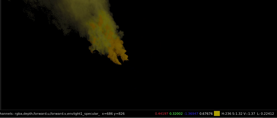
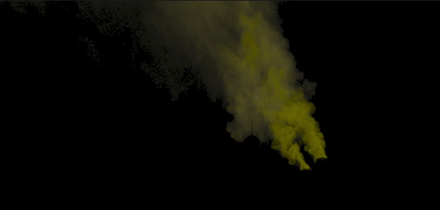
Replacing the ODT if we view using ACES RRT/ODT its fine. Here is an example
This is in Nuke with the ADX10 inverse transform as this would be applied to the images to use the emulation lut or in the grade, the orange areas are all negs and should not look like this. This is before any viewing transform no viewer lut being applied
So if in Nuke you can read in the footage comp in the CG and view it with the aces ODT and it looks fine, then try this:
Set the viewer to Raw. Add an ocioColorSpace node in: ACEScg out:ADX 10. This converts everything to log. Next an ocioFileTransform with your lut and the process space set to ADX 10. If that works you just need to put all that into a view transform in your ocio config.