CLF Spec Review Period

All,

Attached is a PDF of the draft update to the specification. Please review and offer comments as early as you are able to.
CLF_3_0-2019-11-11.pdf (634.2 KB)

Since we very much rewrote a lot of the specification, I fully expect this to be an iterative process and there will be many small tweaks between this draft and what we finally settle upon to publish. That being said, we need to keep momentum, so comments will be addressed constantly in the LaTeX version as they roll in and an “up-to-date” PDF snapshot will be posted each day. I recommend pulling the latest version whenever you go to review, as I expect this document to rapidly improve.

NOTE: The schema and XML diagram still need to be updated to incorporate the new Process Nodes and accommodate the minor changes we’ve made to existing nodes’ accepted attributes. While you are all reviewing and offering comment, I will be working here with Alex (and the tool he’s been using for AMF) to update the schema and generate a new XML diagram.

Thanks.

2 Likes

Here are some particular prompts to consider during your review for which your feedback would be particularly helpful to have:

The entire document needs a read, but please pay particular attention to our new or heavily revised Process Nodes:

  • 5.3.6 - Log
  • 5.3.7 - Exponent
  • 5.3.5 - Range (our favorite node to debate)

Do we still need 5.4 - Array? It is already introduced (in context) in the places it is used. Is it still helpful to describe the abstract case of it?

Are the Implementation Notes (Section 6) still accurate and adequate? Any other notes or changes?

Terms and Definitions: (A section often overlooked in revisions…)

  • Is the included list of terms and definitions still adequate?
  • Should any be added?
  • Should any existing ones be modified?

Examples:

  • Are the examples for each Process Node adequate? Are there additional usage examples needed?
  • I plan to suggest a new “all-inclusive” example for section 7
  • I might also suggest we add functional CLF test files as supplement to this document (as part of the implementation group?)

Today’s version of the document: CLF_3_0-2019-11-14.pdf (598.4 KB)

Here are the (few) changes from the 2019-11-11 draft:

  • Updated object model diagram
  • Updated schema: still working on Log and Exponent details, but overall schema has been improved and errors fixed.
  • added default values to <LogParams> : defaults are set such that linToLog style functions are equivalent to log10 style if no LogParams are provided)

Please review ASAP - even if you can just take a look at a section or two. Please see my post above for feedback prompts.

[for those that know me, I acknowledge the stuck record that follows]

Scott,

I notice that the in the Matrix section 5.3.4 example 3, shows the elements of the matrix at enough precision for them to require at least an IEEE double to represent as they are given to 15 digits, is that intended? a normal 32 bit float can be represented by a maximum of 9 significant digits.

In the example of transforming to and from a half precision value you don’t need that many digits, but with a 32 bit float data type one could argue for needing greater precision in the matrix than the input and output types. As such I wonder about what the expected limit should be.

For preserving the textual representation than 15 digits is enough for double, to preserve the binary representation then 17 are needed, for 32 bit float the numbers are 6 and 9 respectively.

Kevin

I can associate with your obsession with precision, @KevinJW. But given that this is a LUT format, and LUTs are normally approximations of transforms, not precise implementations, is exact precision really an issue here? Throwing more digits than needed at a matrix in the XML file is unlikely to be a bad thing, and allows a more precise implementation to be performed if required.

Below is a dump of my notes made while reading the document:

Section 3 should probably include a definition of a Log transform

3.6 “An IndexMap in its simplest form…” suggests more complex IndexMaps may be used. In fact is CLF not now limited to 2 entry IndexMaps, which simply define a range?

3.7 Could be taken to suggest that the output is based only on the index below that corresponding to the input value, when in fact the pair either side are used. 5.3.2 defines it more clearly.

3.10 Should be clearer that not only 3x3 matrices are supported? Section 4 refers to 3x4, but this section appears only to reference 3x3.

4 “To accomodate irregular spacing, a halfDomain 1DLUT should be used.” Firstly “accommodate” is incorrectly spelled. Also since the paragraph is discussing the regular spacing of 3D LUTs, perhaps the sentence should read “To accommodate irregular spacing, a halfDomain 1DLUT or Log node should be used as a shaper prior to the 3D LUT.”

4.1 ACEStransformID. Do we include the ability to identify an individual node, or sequence of nodes as performing a transform equivalent to an ACES transform, such as CSC?

5.3.2 “For a 1D LUT, one value per entry is used for each color channel”. I think “…used for all color channels” would be clearer.

5.3.2 “<IndexMap dim=2>64@0 940@1</IndexMap>” is not a good real world example. It suggests that 940 maps to the second entry in the array. 940@1023 would be better. Or are 0 and 1 now taken to mean the first and last elements in the array? If so, I beleve this is a change from the previous spec, which used integer indices.

5.3.3 “NOTE: Interpolation methods are specified in D.” Appendix D?

5.3.5 “The Range element can also be used in to clamp values.” Remove “in”?

5.3.5 “While intinct might be that this scale should be a clean bit-shift factor (i.e. 2x or 4x scale), testing with a few example values plugged into the formula will show that the resulting non-integer scale is the correct and intended behavior.” This is true for full range integer data, but for legal range a bit shift is preferable, so that e.g. 8-bit 235 maps to 10-bit 940. Are we concerned about this? The correct conversion could of course be implemented as:

<Range inBitDepth="8i" outBitDepth="10i">
<Description>8-bit to 10-bit legal range</Description>
    <minInValue>16</minInValue>
    <maxInValue>235</minInValue>
    <minOutValue>64</minInValue>
    <maxOutValue>940</minInValue>
</Range>

5.3.7 sRGB EOTF example. I have mentioned previously that this does not in fact exactly match the sRGB spec, and the break point and slope given in the spec are not a perfect solve.

6.1 I feel the bit depth behaviour explanation should go into more detail, perhaps with some examples. When I first began work on my Python implementation, I misunderstood how bit-depth handling was supposed to work. @doug_walker and others kindly set me straight. I think more explanation is merited in this section.

6.5 “…a transform designer and/or the application should insure that output floating-point values do not contain infinities and NaN codes.” Should there be a comment that half-float 1D LUTs are an exception to this? Presumable an identity half-float LUTs which passes NaNs and infs through unmodified is permissible?

6.9 “Conversions from float to integer if required must be done by rounding.” Should we specify a rounding method, or at least note that there are different ones?

9.9 “<CR><LF> vs. <CR>.” Should this read “<CR><LF> vs. <CR> vs <LF>”?

Appendix C notes that IndexMaps with more that two elements are considered an extension to CLF, but then goes on to describe in great detail such an IndexMap. This feels unnecessary and potentially confusing.

1 Like

Thanks Nick. (I’ll respond per item as I address your feedback. I hope this makes it easier for others to chime in on specific points.)

Ah yes, I forgot the term and definition - this is no longer accurate.

But to your bigger point, that aligns exactly with my thoughts. I don’t understand the value of an IndexMap without dim > 2. It seems unnecessary to keep any IndexMap, because isn’t a 2 entry IndexMap essentially a scale/offset like in the Range node? Am I missing something? Can anybody defend a use case where a Range node could not accomplish the same result as an IndexMap with dim=2?

I asked this same question - what do we do when there are multiple ACES transforms concatenated into a single CLF?

A potential solution…Allow for more than 1 of these elements may be present, and specify that they be read in order.
We currently allow unlimited elements in the ProcessList, so this essentially just a labeled version of that. Or, just don’t have these elements at all - they were added in V2 and were barely a part of the spec since they were not even mentioned in the text (only an Appendix).

Or… even though the ACES-related Info elements are just Info and are ‘optional’, maybe we try to keep specific references to ACES out the Common LUT Format (if a user wants to put it in the description, so be it). But couldn’t AMF handle tracking of ACES transforms being applied? It can reference a CLF.

All,

I am currently rewriting the entire bit depth handling section by better fleshing out what was there with examples (per @nick 's suggestion) and removing some of the redundancies and ambiguities that exist in the current “Implementation Notes” sections. I hope to have a new draft posted up tomorrow morning.

In the meantime, if you have any initial comments please submit as you are ready. Any feedback, big or small, is good feedback!

Thanks!

Or, if you don’t want to look at the whole document (but please do!) the new Object Model diagram and current updated schema are attached:

CLF_ObjectModel (2).pdf (57.0 KB)
CLF.xsd (11.9 KB)

The schema adds the Log, Exponent, and ASC_CDL nodes and fixes some errors. (interestingly, though part of the spec, ASC CDL was not included in the V2 schema)

Looks like you’re missing the CDL sub-elements.

As I mentioned at the last meeting, I had also made an updated diagram. I was just waiting to see where we come out on the naming of the Log params. But enclosing now, in case it’s useful.

Doug
clf-diagram_v1.pdf (44.7 KB)

Thanks, @doug_walker. This looks great!

Hey there,

Sorry, it’s taking me a long time to get all my thoughts together; turns out, I have a lot to say about the Info elements – particularly ACEStransformId / ACESuserInfo (in a nutshell, unlike the other Info-level elements, there isn’t an unambiguous, self-evident use-case within the scope of CLF v3, nor is practical / feasible to enforce the requirement or validate their use in many situations. Either get rid of them entirely, or ‘demote’ them to elements belonging to an ACESinfo type (i.e., as with CalibrationInfo), which would have the effect of ‘reserving’ rather than ‘requiring’ their use in certain cases. Phew!)

In the interest of getting you guys feedback before it’s too late, let me respond specifically to the Process Nodes:

  • Log

    • I had an extra-important note about there being a problem with the logToLin and cameraLogToLin equations, but either I broke something on my end, or you guys fixed something on your end. Either way, looks good!

    • I don’t want to rock the boat, since precedent already exists vis-a-vis CTF, but the styles here seem at odds with the convention used in the CDL and Exponent ProcessNodes – specifically, with respect to the use of ‘Fwd’ / ‘Rev’ in the other operators. If I’m being honest, I think ‘cameraLinToLog’ / ‘cameraLogToLin’ feels less awkward than ‘cameraLogToLinRev’ / ‘cameraLogToLinFwd’ (or vice-versa); but from the perspective of implementation, I think there’s far more value in having the Log style attribute convey the same information as ‘style’ effectively does for other ProcessNodes – namely, which algorithm to use, and, implicitly, the ‘orientation’ of the Process itself (even if said orientation is arbitrarily assigned, it’s significant that the orientation is absolutely defined). Higher-level interfaces are, of course, welcome to use the more user-friendly ‘LogToLin’ / ‘LinToLog’ differentiation.

      • In other words, binding specific directions to each binary pair of operands makes different implementations more consistent and easier to reason about, and, again, the direction can be abstracted from the style for user-facing stuff; because it’s quite possible for the direction of a lower level ProcessNode style to become decoupled from that of higher-level objects that implements it – i.e., inverting an OCIO GroupTransform blindly toggles the direction of the Transforms within. If one can reliably split off the last three characters of a style’s value to determine which of the two possible variants of a given set of algorithms to use, the relationship between the ‘directional state’ of a complex high level component, and the exact style of algorithm used at the lower level becomes boolean algebra all the way down.
    • The attribute names in Doug’s diagram, ‘logSlope’, ‘logOffset’, ‘linSlope’, ‘linOffset’, and ‘linBreak’ are all punctuated by ‘Side’ – i.e., ‘logSideSlope’, ‘logSideOffset’, etc. (and also, there’s no ‘linearOffset’ equivalent, and ‘linearSlope’ presumably stands in for ‘linearGain’).

      • Personally, I prefer the inclusion of ‘Side’; even if it may seem redundant from the perspective of someone who already understands the formulas, I found it really helped to demystify and reinforce my understanding of the coefficients and their use in the equations, as well as the equations themselves.
      • Given that we’re also using ‘linearOffset’, I find it far less confusing to use ‘linSideOffset’ than ‘linOffset’.
      • I also prefer ‘linearSlope’ over ‘linearGain’ – I understand what ‘slope’ and ‘offset’ mean, and I can infer what ‘break’ means, in the language of high-school mathematics; ‘gain’ seems unnecessarily domain-specific if the point is to differentiate from the non-linear piece’s ‘linSlope’ coefficient…
      • …UNLESS we can find a similarly domain-specific term to replace the ‘linearOffset’ coefficient for the linear segment. In other words, I find it more confusing that there are two attributes named ‘lin<something>Offset’ than I have trouble with using engineering-oriented attributes to differentiate the linear-segment attributes from the nonlinear; but I have a lot of trouble reconciling ‘linearOffset’, ‘linOffset’, ‘linearGain’. and ‘linSlope’.
      • In summary: Using ‘linear’ vs ‘lin’ to differentiate between the two segments isn’t intuitive; replacing ‘slope’ with ‘gain’, but not doing likewise for ‘offset’ for the linear segment is more confusing than either keeping or changing both ‘slope’ and ‘offset’ consistently; and using ‘linSideBlah’ and ‘logSideBlah’ both clarifies the attributes’ use in the formulas, and helps to differentiate from the attributes pertaining to the linear segment, whatever their names may be.
      • I feel like there was a good discussion regarding this very subject in one of the older OCIO-2.0 tickets, but I can’t seem to find it.
  • Exponent

    • Similar comment as above re: directionality, although it’s much more clear and consistent here. I’d prefer ‘basicPassthruFwd’ over ‘basicFwdPassthru’.
      • (Come to think of it, I guess that means I’d prefer NoClampFwd and NoClampRev" for CDL, but if the schema doesn’t allow for that, I guess… disregard everything I just said! Still would be helpful to grep for ‘Rev’ in LogParam styles. Just sayin.)
    • It would make sense to provide coefficients for Rec.709 and CIE L* equations in addition to sRGB, so long as you’re mentioning them.
    • In addition to offset == 0., it would seem that exponent == 1. causes a divide-by-zero error as well when computing yBreak / xBreak in the moncurve styles, or am I mistaken? This strikes me as a little problematic, given that 1.0 is the default value for the exponent attribute.
  • Range

    • No complaints… yet :slight_smile:

Overall, I found everything incredibly readable and easy to understand, considering the subject matter. I’ve mostly implemented the Log and Exponent operators in Python, to compliment Nick’s previous work (only thing I’ve yet to do is account for structuring and unstructuring various permutations of channel-specific operand sequences into more user-friendly class implementations) – should have something to share quite soon, time permitting!

Which reminds me – I may have missed it, but are there any constraints on the number / combination of ExponentParam / LogParam elements that can exist within a single Exponent or Log Processes? Since each channel is independent of the others, It would be great if the number of elements per Process could be constrained to a maximum of 3 channel-specific or 1 channel-agnostic elements, requiring that additional elements overflow to discrete, consecutive Processes…? Is that at all viable?

All in all, I feel like the Processes included with CLF provides the sufficiently robust toolset the design intends, which is no small feat!
If I could do it all again, I’d ask for a hermite-spline-based soft rolloff processor, but I can do without for now :slight_smile:

I’ll (hopefully) continue to post more as time allows.

Thanks again…!

@nick, I believe I have addressed most (if not all) of your points in this version

  • removed Terms & Definitions
    All the terms are defined in context later in the document. The few remaining definitions weren’t serving much of a purpose. If you’re reading this document and don’t know what a LUT is, then it’s not the document for you. Descriptions of what the nodes are are included in the specific ProcessNode-substitute sections
  • Log Node
    • changed attributes of LogParams node back to match Doug’s terms (per @zachlewis)
  • Implementation Notes
    • moved the notes on XML white space and newline characters up to the XML section
    • made explicit bit-depth handling sections - consolidated a lot of the existing language - hopefully this reads ok
    • simplified the Interpolation Types section - Do we even need this? Can this be removed entirely?
  • Schema
    • other updates
    • added ASC CDL node (surprisingly this was not included even in the previous version of the spec)

I still need comment on the items below.
(If I don’t hear any opinions, I’ll have to make the decision.)

  1. Are IndexMaps are still necessary at all?
    It seems to me that a Range node does the same thing that an IndexMap with dim=2 would accomplish. What am I missing about why an IndexMap would still be useful if it’s limited to dim=2?
  2. Should InputDescriptor and OutputDescriptor be required instead of optional? (suggestion from @nick)
  3. Should ACESTransformID and ACESuserName be sub-elements in an ACESInfo element? (suggestion from @zachlewis)
  4. Should ACEStransformID be applicable on a ProcessNode level rather than on a ProcessList?
  1. Should CalibrationInfo be a part of the specification or not?
    It was, then it wasn’t, then it was again, and currently it isn’t (although it’s still in the schema). If it’s not hurting anything and is optional metadata, it’s probably ok to leave it. Nobody actually has to use it. However, there was concern that it was unnecessary metadata that could easily be tracked using one or more Description nodes. So… is it in or out?
  2. LogParams - Is it wrong that I have the linearOffset as a settable attribute? (rather than having it always computed automatically?)
    To me, tt seems like it might be useful if, for example, I’m copying another formula exactly and they didn’t correctly make the transition between the log/linear segments smooth according to the derivative. (like the discrepancy between the sRGB written spec vs the intended formula)

This version of the document will imminently be “locked” and submitted to the Architecture TAC as the deliverable from this VWG. I am sure there are still typos and small things that the Implementation group will find as they try to implement from the updated specification, and those will be fixed. So the document is not completely “locked”. But we are not adding new features or changing things in a major way at this point in time.

CLF_3_0-2019-11-26.pdf (636.3 KB)

The main difference between an IndexMap and a separate Range node, is that an IndexMap is (I believe) restricted so it always maps a given range to the range of the subsequent table. This means that a 1D or 3D LUT in another format with a defined input range could be converted to a one node CLF, and the resulting CLF could easily be converted back to the original format matching the original exactly. If the input range is broken out into a separate Range node, a LUT converter converting back to the original format would have to apply some intelligent analysis to the two node CLF. And not all Range + 3D CLFs could be accurately represented by a simpler LUT format with defined input range.

I suspect that in many use cases, a CLF may be used to encapsulate a single 3D LUT from another source. And easy cross conversion may be a benefit.

Hello,

Copy-pasting verbatim, and for the public record, the CLF Review notes that I sent, as a TAC member, to the ACES Leadership:


Hi,

Congratulations for the hard work! It was helpful to have followed the process, made the review easier and shorter.

Here are my notes, you will find that a lot of them are stylistic and pedantic but they are striving for improving the consistency of the document. There are a few questions that I would like to hear answers for and at least an important correction that pushed me to reject the proposal in its current state. I have assumed that the maths are correct and did not spend too much time in the interpolation appendixes.

A Common File Format for Look-Up Tables - Review - CLF_3_0-2019-11-26.pdf

Summary

  • [ Rejection Source ] The correction I would like to be made is, actually, after just reading Graeme comments, also about the matrix dimensions, see 27.2.
  • [ Rejection Source ] There are a few hard-coded ranges in the specification in non ASC_CLD nodes, I want to hear why, see 34.1.
  • [ Rejection Source ] How is the compatibility with a particular version of CDL defined?, see 35.2.
  • I’m generally annoyed by the (mentioned during calls) casing inconsistency in many places, this is not great and nobody came with a single good reason as to why it should not be changed. The only ones I heard: There are already some implementations of CLF 2 and changing casing might break them. or It is fine, people will just copy-paste the names.. I’m sorry but this is not a good reason. Any major version update is the opportunity to flatten irregularities like that and it is a shame that we don’t do that here, see 19.6, 28.2. It also goes beyond casing, for example, basicFwdMirror should really be basicMirrorFwd, see 32.1.
  • It would be useful (and consistent) to have generic Log and AntiLog styles that are using the base LogParams, see 29.1.
  • I still think that Range node is badly designed and tries to do too much, even though I’m pleased to see that it is in a better place than a few months ago. I hope this will be addressed by deprecating it and adding specific Remap and Clamp nodes in CLF 4.0.
  • I would be keen to discuss specifically about 8.1, 15.2, 22.1, 23.1.
  • As some VFX studios existence spans multi-decades, it has become a super critical information to perform archeology on old shows and chase information. One can use the Copyright element but I reckon having dedicated elements would permit to establish good practise to track that down because Copyright @ The Moving Picture Company or Copyright @ Pixar is not really helping here.
  • Consistency needs to be improved, it is a matter of doing a few search-and-replaces, rewording a few things. This is a technical document and must be hyper-consistent. I’m happy to help with that on Overleaf.

Notes

  1. Any Page: 3by1D or 3x1D: need to pick a variant, I would favour the latter as the former does not look elegant.
  2. Any Page: 3 by 3, 3 by 4 or 3x3, 3x4: need to pick a variant, I would favour the latter for reasons previously stated.
  3. Any Page: 3DLUT or 3D LUT: need to pick a variant, I would favour the latter for reasons previously stated.
  4. Any Page: XML file or CLF file: need to choose one variant or the other, I would favour the latter after introducing it, e.g. A CLF file is a XML file [...].
  5. Any Page: There are many variants around ProcessNode: Process Node, process node, ProcessNode, the document needs to settle on one.
  6. Any Page: A lot of the ProcessNode(s) are introduced like so: The LUT1D element, this should be consistently changed because element has a particular meaning in XML and in CLF itself. What about something along the lines of The LUT1D derived process node [...].
  7. Any Section Title: They need to be consistently cased: Input and output to a ProcessList should be Input and Output to a ProcessList.
  8. 3 Specification (Page 7):
    1. the sequence of transformations is described as a node-graph: graph feels quite pompous given we are talking about a sequence (list). It may also make people think, incorrectly, that CLF might be an Undirected Graph, a Multi Graph, etc…, while it is, at best, a super simple Directed Acyclic Graph (DAG), without any explicit edges. If it was effectively a graph while not having called ProcessList, ProcessGraph? I would be keen for that to be disambiguated or if the intent is to have vertices with multiple explicit edges in the future, for any reason, having it explicitly stated.
  9. 3 Specification (Page 7):
    1. Each XML file shall be completely self-contained, requiring no external information or metadata.: requiring is more appropriate in the context of this technical document.
  10. 3 Specification (Page 8):
    1. Arbitrary ordering of list elements is not supported in the format
  11. 3 Specification (Page 8):
    1. For simplicity’s sake,: Is not sake being too mundane here, in a technical context?
  12. 3.1.2 Declaration (Page 8):
    1. Remove the paragraph that says The file should contain the following [...], as it is redundant with 3.1.3.
  13. 3.1.3 XML version and encoding (Page 8):
    1. XML Version and Encoding
    2. a starting line that identifies the XML version number and encodingvalues.
  14. 3.1.4 Comments (Page 9):
    1. brackets like so:
  15. 3.1.7 Newline Control Characters (Page 9):
    1. and Windows systems: A Unix system can be a personal computer (PC).
    2. I would be keen to hear practical situations where the newline character has been an issue because this is a quite hard thing to enforce and people tinkering with text editor will surely mess with that.
  16. 4.1 Array (Page 9):
    1. The Array element contains: there should be an emphasis on the Array term here and generally, when the document references a specific construct, there should be an emphasis on it.
  17. Figure 2 (Page 10):
    1. The diagram should be moved to another page, it cuts the description of the dim attribute, making it hard to follow.
  18. 4.1 Array (Page 11):
    1. The section should start with Description: like for Array .
    2. 4 entries represent the dimensions: It might be my english, but have sounds weird here, likewise for the others.
    3. of a 3D cube and the number of components per entry
    4. with 3 color components
    5. [ Rejection Source ] There is an important issue with the dim attribute for the matrices that I discuss in point 27-1.
  19. 4.2 ProcessList (Page 11):
    1. This section starts with Description: but not Array ?
    2. A LUT designer can allow floating-point values to be interpreted by applications and thus delay control of the final encoding through user selections. I don’t understand what this means.
    3. NOTE 2: This note should be in 4.4.5, it is currently misplaced as we are talking about the node container and not any specific node.
    4. NOTE 3: This note should redirect toward the ACEStransformID definition down or be moved as it is confusing here. It could be reworded as follows: This attribute may also store the ACEStransformID, cf. definition below, which is [...]
    5. This is a question for the whole document: Should the Attributes ordered by requirement and alphabetically? Right now it is neither.
    6. I mentioned it a few times but I don’t like the fact the casing is inconsistent.
  20. 4.2 ProcessList (Page 12):
    1. At least one ProcessNode must be in the list. : What about The ProcessList must contain at least one ProcessNode?
  21. 4.3 ProcessNode (Page 12):
    1. No line return after Description:
    2. A ProcessNode element represents a primary color transformation: What does primary means in that context?
  22. 4.3 ProcessNode (Page 13):
    1. “32f”: 32-bit floating point (single precision) No support for 64f double-precision? This contrasts with 5.3 recommending that all calculations be done in at least 32-bit floating point.
    2. The Attributes should be ordered in a meaningful way as previously stated.
  23. 4.4 Substitutes for ProcessNode (Page 13):
    1. Substitutes for ProcessNode: The first consumers for the specification will be software engineers, I would favour using terms they are used to and make sense in software development, e.g. Subclasses, Inheritors, Derived Nodes, etc… especially when it is stated that the attributes and elements are inherited.
    2. NOTE: Additional substitutes for ProcessNode could be introduced in future versions of this specification. Is this note required here? Seems like stating the obvious.
  24. 4.4.2 LUT1D (Page 13):
    1. Linear interpolation shall be used for LUT1D: Might need more explanations on as to why and put an emphasis that it is a recommendation, especially for non-native english readers.
    2. dim: I almost wish this attribute was called shape :slight_smile:
  25. 4.4.2 LUT1D (Page 14):
    1. An IndexMap is used to define [...] or An index map is used to define [...], consistency oblige :slight_smile:
    2. an integer that indicates the number of items in the list. The only valid value is 2. Any specific reason to require dim here if it is always the same value?
    3. This attribute is optional but is fixed to "linear" as the only allowed value: With respect to my comment in 24-1, is it shall or must? :slight_smile:
    4. halfDomain, rawHalfs Would be great to have better description consistency: those two attributes start by giving their default value first while interpolation gives it at the end of its description. More explanation and examples would also be welcomed here.
  26. 4.4.3 LUT3D (Page 15):
    1. with 3 color component color
    2. NOTE 2: Array is formatted differently when it is contained in a LUT1D or Matrix element. Please explain how, seems like it is coming out of thin air.
    3. The Examples sub-section looks like it is part of the Index Map element but is not actually, it should be dedented accordingly.
  27. 4.4.4 Matrix (Page 16):
    1. An offset matrix may be defined using a 3x4 Array
    2. [ Rejection Source ] dim does not look correct here because it is not giving the shape of the Array but is a mixed bag between the effective shape and the intended number of component the Array is meant to act on. The elements of dim multiplied together should be equal to the number of elements in Array. This is extremely problematic. With all the previous cases of Array, and while using Matlab or Numpy, one can simply tokenize the data, convert to number representation and reshape but here it would break for no obvious reasons.
  28. 4.4.5 Range (Page 17):
    1. I still think that this node tries to do too much and is badly designed. The very long specification speaks for itself and I don’t like it. I sincerely hope this will be addressed by deprecating it and adding specific Remap and Clamp nodes in CLF 4.0. I had to take my breath after reading its description… :slight_smile:
    2. Why are the Elements title-cased here? Consistency, consistency!
  29. 4.4.6 Log (Page 19):
    1. It would be useful (and consistent) to have generic Log and AntiLog styles that are using the base LogParams.
    2. specifies the form the logarithmic function to be applied: Consistency again.
  30. 4.4.6 Log (Page 20):
    1. logarithmic function with a gain factor , an offset and a linear segment.
    2. assume integer data is normalized
    3. The equations are starting to be hard to read and overcrowded, might need to define some indirection variables and use where "Foo" is equal to:, especially for y -logSideOffset / logSideSlope.
  31. 4.4.6 Log (Page 21):
    1. by using the derivative of the logarithmic portion of the curve: More consistency.
  32. 4.4.7 Exponent (Page 22):
    1. "basicFwdMirror": Direction should be a suffix, e.g. “basicMirrorFwd”, “basicMirrorRev”, “basicPassthruFwd” and “basicPassthruRev”.
  33. 4.4.7 Exponent (Page 23):
    1. "moncurveFwd" : “monCurveFwd” Also, should there be a note that this one is intended to mimic a monitor curve hence the name?
  34. 4.4.7 Exponent (Page 24):
    1. [ Rejection Source ] Must be in the range 0:01 to 100:0, inclusive. Default is 1.0: The specification, abstracting ASC CDL, is generally free of any restrictions such as that one, which is great. Are there any really really good reasons for having those? They are also different from ASC CDL ones. Likewise for offset.
  35. 4.4.8 ASC_CDL (Page 25):
    1. they are always interpreted as if the bit depths were float.: This one is oddly worded, does this mean that 8-bit is effectively 8.0-bit? What about saying something along the line of they always act on floating-point data?
    2. [ Rejection Source ] How is the compatibility with a particular version of CDL defined? Say ASC CDL 2.0 is released, how do we make sure it does not break CLF? It seems important that we define which version of ASC CDL is supported in a dedicated attribute.
  36. 5.1.1 Processing precision (Page 26):
    1. Processing Precision
    2. shall not affect the quantization of color values., this is oddly written, what about an explicit: do not impose that the colour values should be quantized to to the particular bit-dpeth and converted to integer, only that they should be scaled accordingly. Upon further reading, it is actually repeated in 5.1.2 but this is super important, so might as well double-down on this one.
  37. 5.1.2 Input and output to a ProcessList (Page 27):
    1. Input and Output to a ProcessList
  38. 5.1.3 Input and output to a ProcessNode (Page 27):
    1. Input and Output to a ProcessNode
    2. the formulas in the Log, Exponent, and ASC CDL elements assume that data is normalized 0-1., because there are so many ways to normalise data between 0-1, it seems like it would be important to expand 5.1.4, making it a dedicated section about everything normalisation and reference it across the document, for example in 4.4.6: the Log node assume integer data is normalized to floating-point scaling, see Section 5.1.4.
  39. 5.3 Efficient Processing (Page 28):
    1. all calculations be done in at least 32-bit float precision.`
  40. 5.5 Floating-point Output of the ProcessList (Page 28):
    1. Floating-point Output of the ProcessList
    2. do not contain infinities and NaN representations.: code is not really appropriate here.
  41. Appendix A (Page 30): I suppose that the example LUT (abstracting the abridged values) is valid against the Schema?

Hi Scott/JD,

Sorry that it has taken me awhile to compile my feedback, but it is finally enclosed below.

First, I want to say thank you for all the work pulling together the unwieldy raw material from many hours of conversation and various forum posts into a coherent document – it was no small task. There is some work remaining, but it’s awesome you and JD have gotten the bulk of the writing accomplished for us.

Before getting into specific points, here is my take on a few of the issues discussed on the forum in recent posts:

  • ACEStransformId / ACESuserInfo – Yes, I agree with Zach that these should go under the Info element (in fact the v2 spec was contradictory on this subject but did indicate they should go there in one part). We also may want to mention and/or illustrate the tie-in to AMF since the IDs seem to play an extremely important role there.

  • LinearOffset should definitely be removed from Log. We don’t want to allow people to create discontinuous Log transforms.

  • I would support your suggestion to remove the IndexMap entirely since one of our goals was to try and simplify the job for implementors. Nick raises a potential use-case, but the utility IndexMap brings is not worth the significant complexity (IMHO).

  • Regarding the Array dim attribute for Matrix, this has been in the spec since v1. The Lut1D has [length, chanels], the Lut3D is [dim1,dim2,dim3,chanels], and Matrix is [rows,cols,channels]. The v1 and v2 specs (e.g. see pg 12) contemplated allowing 4 channels (RGBA) and this was discussed during some of the meetings. But we decided the channels element must always be 3 in the current version of CLF. Perhaps the syntax could have been done in a clearer way by the original ASC committee for v1 but it is far from unworkable. In fact from a parsing standpoint it is extremely simple, whereas other approaches (e.g. breaking it out into separate attributes) would be more complicated to implement.

And now here are some more detailed comments on the individual sections:

3

  • At the end of the fourth paragraph please add: “Implementations may process 1-component transforms by applying the same processing to R, G, and B.”

4.1

  • At first glance, I did agree with the earlier comment questioning whether the separate Array section is really needed, as the content is repeated elsewhere already. But perhaps in light of recent feedback it would be helpful to keep it since it illustrates the structure of the dim attribute for Lut1D, Lut3D, and Matrix all in one place.

4.2

  • Please add: “The compCLFversion corresponding to this version of the specification is “3.0”.”

4.3

  • I think it would be clearer to describe the bit-depths as “a string that may be used by a ProcessNode to help describe the scaling of parameter values. Note that this string is for formating purposes and does not control processing precision.” If you talk about it in terms of “expected input/output values” it leads people to go down the wrong path about how to think of these attributes.

4.4.1

  • Please add: “The inBitDepth of a ProcessNode must match the outBitDepth of the preceding ProcessNode (if any).”

4.4.2

  • Please add: “The scaling of the array values is based on the outBitDepth (the inBitDepth is not considered).”
  • As per the v2 spec, please add: “Implementations are not required to support LUT1Ds longer than 65536 entries.”
  • As stated above, I’m not opposed to keeping it if people really want it, but I still don’t feel IndexMap is worth the effort.

4.4.3

  • Please add: “The scaling of the array values is based on the outBitDepth (the inBitDepth is not considered).”
  • I think the last sentence of the first paragraph adds more confusion than help. It doesn’t really change the lookup, per se.
  • The high end of the index map is not 1, it is the grid dimension minus 1.
  • Please restore the following sentence from the v2 spec “LUT3Ds have the same dimension on all axes (i.e. Array dimensions are of the form ”n n n 3”). A LUT3D with axial dimensions greater than 128x128x128 should be avoided.”

4.4.4

  • Change LUT to Matrix (2nd paragraph).

4.4.5

  • The default cannot change from the v2 spec, it must remain a clamp.
  • It might be clearer to forbid the option to omit all min/max values. No one would ever need this – I think it was intended as a convenience to keep bit-depths matching, but it may cause more confusion than help.

4.4.6

  • LinearOffset should not be a free parameter, it should always be calculated.
  • Eq. 4.19 is not really the derivative, it’s that with linSideBreak substituted in.

4.4.7

  • I’m thinking we should add the mirror option for moncurve too.
  • The exponent attribute is always required.
  • The valid exponent range you stated is only for the basic styles, the valid moncurve range is [1,10] (allowing it to go below 1 breaks the formulas).
  • The Description element of the first example doesn’t match the params.
  • Please remove the statement about “similar but different to 61966-2” (They are the same to within rounding error. People will think you are referring to the gamma 2.2 debacle, which is not what we want.).
  • If you want to include values for all three common curves, the constants are – sRGB: (2.4, 0.055), L*: (3, 0.16), Rec.709: (1/0.45, 0.099).

4.4.8

  • The CDL spec only places non-negativity bounds. Do we really want to place upper bounds?

5.1.1

  • Remove paren at end.

5.1.2 and 5.1.3

  • During one of the calls I thought we had agreed to the bit-depth description I posted on May 1. The spec now says something quite different. The description as it stands now is not workable for implementors. Would you like me to propose new wording, or do you want to have a call to discuss, what is your preference on how to rework this?

5.3

  • In general, combining operators will result in substantially different results and should only be done as a last resort. I think the wording needs to discourage this more strongly. Also, it should clearly state that any such approximation should be compared against the original transform, which is the reference.

5.4, 5.5, and 5.6

  • I find these confusing and am not clear what value they add above the actual interpolation directions in the appendix and other material already provided elsewhere. I would vote to remove them.

5.8

  • This should only apply to elements outside the Info block. Unrecognized elements in the Info block are fine and may simply be ignored.
  • Also, I don’t think Description should necessarily be used for arbitrary metadata if it is not basically a description. Other types of stuff could be put in new elements inside the Info block.

6

  • We need better examples. If you want to include a complex example, you may want to consider an ACES2065-1 to ACEScct transform. Let me know if you’d like me to provide this or others.

App. A

  • I don’t think this should be normative. In fact, I would vote to move it to separate file.

App. D

  • Update parameter names.
  • Add paren to eq. D5

I haven’t reviewed v1 or v2 nor read them in details but I would have flagged it likewise.

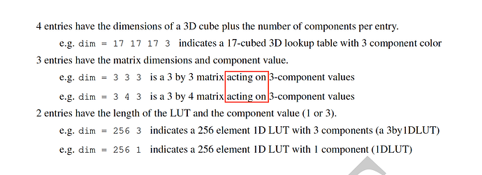
Let’s say I’m looking at that from a data scientist standpoint that uses Multi-Dimensional Arrays in for example Matlab, Fortran, Numpy, Tensorflow, Julia, name-your-MDA implementation etc…

With CLF definition of dim given as follows:

The dim attribute provides the dimensionality of the indexes: No, it does not! The case for the Matrix does not comply with that definition. Either the attribute must be renamed to something else, e.g. almostDimButNotQuite :slight_smile: or the definition changed and the way the Matrix case is specified updated accordingly.

The LUTxD are effectively describing the axes/dimensions of a Multi-Dimensional Array:

  • 17 17 17 3 indicates a 17-cubed 3D lookup table with 3 component color
  • 256 3 indicates a 256 element 1D LUT with 3 components (a 3by1DLUT)
  • 256 1 indicates a 256 element 1D LUT with 1 component (1DLUT)

Multiplying the indexes together indeed gives the size of the array, which is exactly what one would expect. The channels are implicitly accounted in the tail of the array, i.e. the last axis of the array.

For the Matrix case:

  • 3 3 3 is a 3 by 3 matrix acting on 3-component values
  • 3 4 3 is a 3 by 4 matrix acting on 3-component values

dim gives BOTH the axes AND something else, it is not surprising that the text had to be formulated differently to accommodate for that.

Cheers,

Thomas

PS: I haven’t fully read this thread yet, but I agree with mostly everything I read so far!

Something I forgot to add in my notes but came apparent as I started to review AMF and will also post in my AMF notes: I would like to see native support for indicating the author(s) and contact(s) information.

As some VFX studios existence spans multi-decades, it has become a super critical information to perform archeology on old shows and chase information. In CLF, one can use the Copyright element but I reckon having dedicated elements would permit to establish good practise to track that down because Copyright @ The Moving Picture Company or Copyright @ Pixar is not really helping here.

Cheers,

Thomas

PS: I will amend my notes above accordingly.

@thomas @doug_walker
Thanks both for your detailed feedback. It’s nice to have people checking my work as its easy to mess things up with the reorganization of the document and working from the previous words. I’ll work today to incorporate your comments - they will certainly make the text stronger.

As I go, I will compile a list of remaining questions and/or contradictory feedback that the group will need to settle. (e.g. matrix dimensioning scheme)

I will also record any major changes to the substance of the specification - i.e. moving ACEStransformIDs into an Info element - so that everyone is clear on which refinements were accepted - and to give anyone vehemently opposed a chance to respond.

2 Likes