Actually, let me use the value from the topmost purplish pixel that becomes completely black:
(screenshots were made with a rec709-like viewer lut applied directly on the logC footage, no primaries shifting)
LogC: (0.55338, 0.59590, 0.84154)
Yxy: (-0.16389, 0.012537, -0.01005)
Clamped Yxy: (-0.16389, 0.17023, 0.07115)
LogC: (-1.37168, -1.61263, -8.13683)
You have a negative Y value there that you are leaving unchanged. Remember, a gamut is really a volume, not a triangle, so bringing x and y to within the 2D triangle is not necessarily sufficient to bring the colour within gamut. I think that modifying x and y, but leaving Y negative (therefore representing an “unreal” colour) leads to the negative LogC values, and so to the black pixel at output.
Yes, I noticed the negative value in Y.
Isn’t the Y supposed to represent the brightness of the pixels, with x and y representing chromaticities?
If yes, then how can I obtain a negative brightness?
Because cameras aren’t perfect colour measuring devices, matching human vision. Many engineering compromises are made when designing a camera, for perfectly valid reasons. One result is that while the camera matrix results in good estimates of the tristimulus values for most colours, particularly things like flesh tones (which the matrix is biased to minimise errors in) some colours will not be measured so accurately. And certain light sources, like very narrow spectrum LEDs, will result in large errors, causing anomalies like this. It doesn’t mean it is a negative brightness. It means that a negative value is required for brightness to make the maths work.
Got it.
It’s a complex subject. I guess the CIE-Yxy space wasn’t really designed with these extreme values in mind either. (do they still count as visible colors if they blind you while looking at them and you can’t distinguish them from another light source?)
In the meantime I grabbed the matrix from this post: Colour artefacts or breakup using ACES which is helping for these highlights, but is not really different from my original solution of keeping it linear AWG.
Since the color shift is too pronounced on some of the clothes in my plate I’m restoring these via a difference key so that only these crazy highlights get affected. Not ideal but it gives me the most visually pleasing results.
CIE xyY should fine for any kind of dynamic range really (or any colourspace given you are working with unclamped floating point values), as mentioned by @nick, the negative values are coming from the un-perfection of our devices from an hardware/software standpoint.
I kept going with my tests, from this other topic: Path: ACEScg to regular sRGB? (Nuke 10.5v1, ACES 1.0.3) it made me want to do more tests using sRGB.
Posting here to not pollute somebody else’s thread. I downloaded OCIO ACES 1.0.3.
Trying to do a simple sRGB to ACEScg I noticed really high values, which surprised me. I should have noticed from my test9 above that the white point wasn’t sticking to 1, but I was looking at color shift at that time and completely missed it.
Test 10: sRGB > Linear (Looking at transfer curve only)
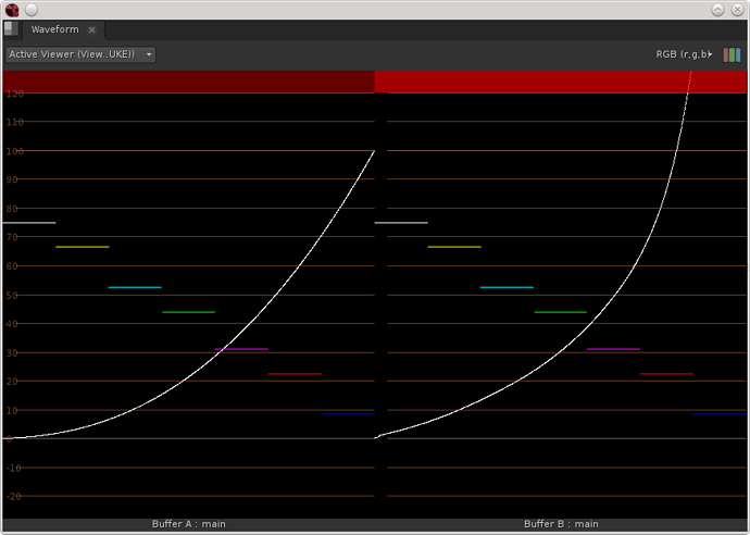
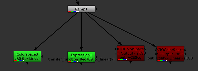
Here I’m testing 4 different ways to apply the transfer curve (using a greyscale input so that gamut/primaries transform won’t have any effect).
The two green nodes have the same output, left curve on first picture, and the two red nodes have the same output, right curve on first picture.
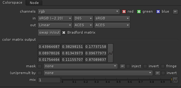
The first node is using a nuke colorspace setup this way:

The second one is using the transfer function I found in the OCIO general.py:
def transfer_function_Rec709_to_linear(v):
    """
    The Rec.709 transfer function.

    Parameters
    ----------
    v : float
        The normalized value to pass through the function.

    Returns
    -------
    float
        A converted value.
    """

    a = 1.099
    b = 0.018
    d = 4.5
    g = (1.0 / 0.45)

    if v < b * d:
        return v / d

    return pow(((v + (a - 1)) / a), g)
The third node is OCIO colorspace with input as; Output - sRGB and output as ACEScg
The fourth node is OCIO colorspace with input as; Output - sRGB and output as Utility - Linear - sRGB
I would have expected all 4 to match. Were my expectations wrong? Was my execution wrong? or is OCIO wrong?
Your expectations were wrong.
The OCIO transform from ACEScg to Output-sRGB doesn’t do the same thing as the the Nuke colorspace node. Nuke’s colorspace node only applies the official sRGB EOTF (transfer curve) and scales the gamut in a very simple way.
The OCIO output transform uses the ACES RRT to apply an ‘S’ curve (also called tonemap, filmlook, soft-contrast) to compress the shadows and the highlights. It also scales the gamut in a more intelligent way to avoid clipping artifacts. It does a bunch of other things to mimic film a little bit (I would really like to see a complete list of what the RRT does in detail). And after all this it applies the sRGB transfer curve.
This is why when you do the reverse transform (which is amazing that it can be done in reverse), the compressed highlights are recovered to their original values, well above 1.0 floating point value. Note that going from ACEScg to sRGB and back will not give you a perfect copy of the original, but close. The process is lossy.
thanks @flord.
That seems to correspond with my observations (not my expectations).
I’m also noticing it is lossy the other way around sRGB>ACES>sRGB.
There are a few other losses here and there that I am noticing, and trying to define if it is due to the math employed (maybe rounding errors because of 32bit limitations) or due to the OCIO implementation (LUT limitations).
In order to do that though, I need to figure out the full chain of operations and re-implement it mathematically rather than via OCIO to compare.
So, I found the matrices for AP1 > AP0, AP0 > XYZ, XYZ > rec709 (sRGB is calling that same one). And I have the linear>sRGB curve from previously.
It looks like the RRTs are the spi3d files in the OCIO folder? Log2_48_nits_Shaper.RRT.sRGB.spi3d dor exemple. I haven’t found the actual code for them nor which one exactly to use, nor where it goes in the order of operations.
There is only one RRT (and many ODTs) but it involves a whole series of operations. You can find these in the RRT.ctl file in the ACES GitHub repository. I would not suggest you try constructing it out of mathematical operations yourself. It is far from trivial.
You could use CTLrender to apply a series of .ctl files to an image. But I do not expect you to find anything visibly different from what you see with OCIO. OCIO’s LUT implementation is not perfect, but the imperfections are not normally visible to the eye when examining an image. They can be seen on a scope when pushing OCIO to its limits, as in your Test3 earlier in this thread.
[quote=“nick, post:31, topic:892”]
There is only one RRT (and many ODTs) but it involves a whole series of operations. You can find these in the RRT.ctl file in the ACES GitHub repository. I would not suggest you try constructing it out of mathematical operations yourself. It is far from trivial.[/quote]
I managed to match my curve by applying both InvRRT.sRGB.Log2_48_nits_Shaper.spi3d and Log2_48_nits_Shaper_to_linear.spi1d, however as soon as I introduce color, things do not match anymore, and I can’t seem to find the right order to apply the operations. Or maybe on the OCIOFiletransforms I need to pick a different working space.
As per rebuilding thing mathematically, while not trivial I’m pretty comfortable with that. Of course I would rather not, but I feel like I won’t be resting until I find out each operation applied to my image. Not that I really need it, but I don’t like using tools without understanding exactly what they do.
If I was to manage to obtain the same result as the OCIO colorspace using the spi3d files that would probably be enough for me to understand what is happening.
I’ve been testing everything with scopes open, barely looking at the image itself, and I noticed a few times where it did seem to breakdown. I haven’t used the CTL render so far, I’ll give that a try.
Thanks
Erwan,
Can you try out a test for me as I’ve been trying to learn more about this topic. I’ve made a cube that will go from LogC (El800) to ACEScg (integer [0-1] input to float output). Can you try it on one of your strong blue light plates and see what happens?
I run it with OCIO but let me know if you need some ocio_config for it.
Best Regards,
Bill
Hi @bmandel. I’ll test it out.
@bmandel Your LUT gives a result very similar to the default OCIO colorspace, but handles these bright blues slightly better. While there are no negative values anymore, these highlight turn bright Magenta,
Original (LogC): 0.66175, 0.74450, 0.95600
ACEScg: -0.14514, -2.37891, 38.40625
LUT: 0.99363, 0.26347, 38.49413
Yes but for ACEScg…what do you get with the image when you go through this lut to ACEScg then run a RRT+ODT of your choice on it? (still will go magenta because it’s already headed that way. Seems like should be some way to desaturate and hue preserve those colors to the point that they don’t go negative. I get 234,130,250 putting it through RRT+709ODT so still very magenta (not florescent blue)
I don’t know what I did wrong, but now I’m getting a different result, with this highlights getting pure blue with your LUT and negative values rather than Magenta. (Using a different OCIO config, maybe there is mismatch between them, as the original one I did the test in has a custom rec709ODT).
When I put it though the RRT + 709ODT, I get these almost pure blue values. (0, 0.06, 1).
I got work to do, so will check why it wasn’t consistent later on.
Hello,
Just wanted to ask a question regarding this post :: We are currently looking to implement a ACES workflow.
I wanted to understand a bit more about the texture workflow. This was very help in confirming some suspicions.
If we are outputting textures from mari (color based) as linear what is the process to convert them to ACEScg before rendering? Is it using a colour matrix such as from this useful site?
i can only see SRGB to ACEScg (CAT02) however.
http://colour-science.org/cgi-bin/rgb_colourspace_models_transformation_matrices.cgi
Any useful inputs would be much appreciated as i fall futher down the ACES rabbit hole.
Kind Regards
The process is a matrix conversion and possibly incorporating a CAT conversion from the initial white to the destination ACEScg D60 white. It is possible to use a matrix that just uses a Von Kries adaptation (normal color space conversions). For many cases, it is better to let the colorist
do white adjustments but for visual effects you are probably trying to get them all to the same place. ACES generally is using the Bradford
transforms though more often in the forward direction to D65. I wouldn’t say that there is anything wrong about other CATs from the website, but testing and color correction would be needed. Assuming that the files are linear light, then just a matrix could do the conversion.
However, there are some edge-of-gamut and negative value roll-over issues that can happen with a 3x3 but are pretty infrequent. I think of it more as taking the ‘red pill’ instead of the blue – or is it the other way around, can’t remember. 
Good Evening Jim,
Thankyou for your input and advice. I will run some tests using a matrix conversion and the Bradford CAT
I presume the same matrix should be applied to all HDRI’s/Lgt textures
I think i will need multi-coloured pills 
Thanks again

