Color primaries shifting and Negative values (OCIO) confusion

Hello all.

After we noticed some heavy negative values in some plates we were comping in Nuke, I decided to take a deeper look at our ACES workflow, and ACES in general.
I hoped it would enlighten me, but I’m coming out of my reading with even more questions than before, and quite a bit of confusion. I am not even sure how to phrase some of the questions I have, so I’ll give a bit of backstory.

I’m coming from a Nuke/OCIO (pre-ACES) background, and feel all good with all the “regular” color-spaces, and going between linear/sRGB/rec709/AlexaLogC using ‘gamma transforms’ (that may not be straight gamma transforms, but do not involve shifting primaries).

Now, on this specific project I am working on, a plate shot on Alexa (LogC - EI800) has a very strong, very blue light. Using the old-school AlexaV3LogC to Linear, no problems, the plate looks quite good.
However, using ACES (via OCIO ACES 1.0.1) [Arri V3 LogC (EI800) >> ACEScg] the very strong blue highlights are causing the red and green pixels values to go into negative values.
Example: A pixel on the (LogC) plate with a value of (0.650, 0.752, 0.954) becomes (-0.294, -1.803, 37.875)

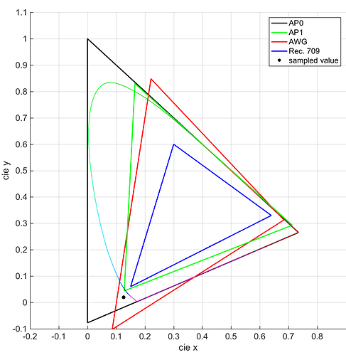
I am assuming this is due to the the shifting of the primaries. Is that correct? Is that supposed to happen? I found the following graphic to be helpful.

Now in terms of Primaries, it was my understanding that sRGB, rec709 and Linear all used the same RGB primaries, and a white point of D65. (Is that correct?)

I was also under the assumption that ACEScg and Linear were equivalent? (CG renders in Linear and ACEScg are 100% identical).

I have done a few tests in Nuke to try to understand better what is happening in all these color transforms,
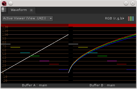
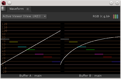
(Left: Original Curves, Right: Color Transformed)
All of them use a Greyscale gradient as the base, which I grade different ways before running through the OCIOColorSpace node.

Test1: ACEScg to ACES - rec709
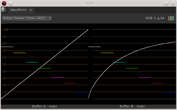
So far so good, things behave like I was expecting them to behave, similar to non-ACES

Test2: ACEScg to ACES - rec709
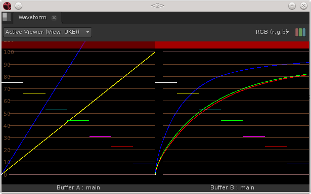
Gaining up my blue channel by 2 (R & G untouched) we start noticing some shift between red and green. Is that due to the shifting primaries?

Test3: ACEScg to ACES - rec709
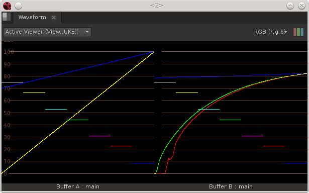
Now I lift my blue channel by 0.7.
We still see red and green shifting from each other, plus red acting funky. The white point doesn’t seem to get affected though.

Test4: ARRI - V3 LogC (EI800) - Wide Gamut to ACEScg
(these are a bit confusing, as I’m giving a linear gradient input to a colorspace node that expects a logC input)
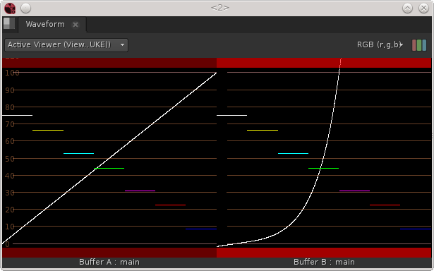
I’m getting negative and huge values, fair enough, as I feed it values from 0 to 1 that would be really extreme values to get in LogC.

Test5: ARRI - V3 LogC (EI800) - Wide Gamut to ACEScg
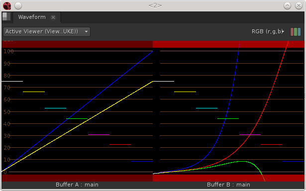
Now I gain down my Red and Green to 0.75. That green curve goes way into negative. That is where my issue is coming from. Now one could argue that my original curve doesn’t respect LogC values, so let’s do one more test.

Test6: ARRI - V3 LogC (EI800) - Wide Gamut to ACEScg
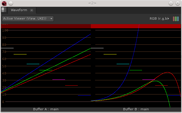
This gradient linear gradient is now mapped to the actual darkest and brighest pixels from my Alexa plate, meaning that in theory it’s entirely within the LogC Wide Gamut Once again Green and Red are dipping down.

Test7: AlexaLogCv3 [non ACES] to Linear [non ACES] to ACEScg (via Lin AP1)
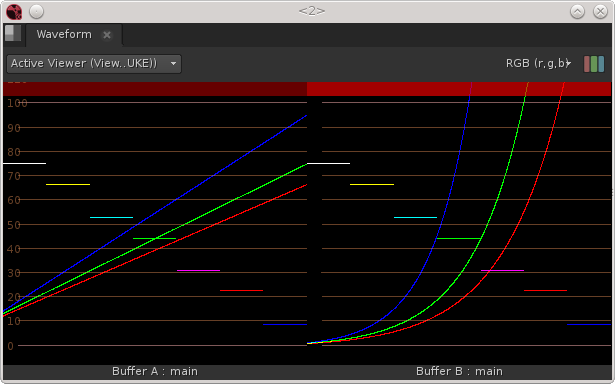
This is more what I am used to, and gives me a result I can easily use,

Can anyone tell me if this is all expected behavior? If so how to deal with it? These are green-screen shots and need to be keyed, which we can’t do properly with these areas of negative values.
My workaround is to ignore ACES, key and comp in linear, then put back to LogC and finally apply the LogC to ACEScg lut to get back in the pipeline (internally using ACEScg for renders).

Thank you.
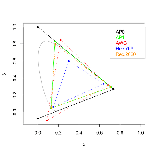
Yes, the negative values you are seeing are resulting from the different primary encoding. I’ve recreated your chromaticity plot with the example value you provided added. You can see that it’s within the AWG triangle but outside the AP1 triangle. In order to represent that chromaticity in AP1, the encoding requires a negative red and green value. Note that this triplet would be all positive in AP0 (because it’s inside the black triangle).

Just wanted to respond to this one point quickly before examining your other questions/examples.

Thanks for this quick answer, I hadn’t tried to plot the color on the graph.
I’ll wait for answers of the rest of my questions before I ask more if needed.

Just saying “Linear” doesn’t specify primaries. ACEScg and ACES2065-1 are both linear, but have different (AP1 and AP0) primaries. If your material is in an AP1 based log space (ACEScc, ACEScct, ACESproxy) and you simply linearise it, then the resulting linear data will be ACEScg. If you have LogC AWG and you linearise that using the the traditional Nuke 1D linearisation, you will get linear AWG, not ACEScg. OCIO transforms normally transform both transfer function and primaries.

What you are seeing there is the result of pushing OCIO’s LUT based implementation to the limits. Applying the same transform using CTL does not result in the distortion in the red channel.

Hi @nick, thank you so much for the clarification. It’s not far from what I thought was happening, but it was based on speculation, and it’s great to get clear answers.
So I guess I’m used to use Linear AWG for comp in Nuke.
How would one handle the negative values resulting from working with Alexa plates in ACEScg? It’s visually weird as these areas are bright highlights that become very dark, and keyers don’t like it at all.

Also as a side question, are AP1 and RGB primaries similar? On the CG side for linear workflow we usually work with linearized sRGB textures, that then get rendered “as is” both for the old linear workflow and the new ACEScg workflow. If the primaries are similar I think we’re good, but if they are similar that means we’re missing one step of putting our textures into ACEScg first?

I suppose you mean “are AP1 and sRGB primaries similar?”

The answer is no, not at all. In this graph, the smallest triangle is the sRGB gamut and the largest one is the ACEScg gamut.

So yes, you’re missing a step in your CG pipeline. You have 3 choices.

  • You can continue to work your CG as before and render and send the images to comp. And ask the compers to convert the images from linear-sRGB to linear-ACEScg. And prey that they never forget.
  • You can convert all your color textures from sRGB to ACEScg. But only your color textures: diffuse color, emission color, spec color, etc. Don’t do this for vector displacement images!
  • You ask your texture artists to work directly in ACEScg. This requires a good comprehension of color management in Mari and/or Photoshop.

Over here, we use the second option. We process all our textures to be mipmapped and we use the same step to convert the color textures (based on their name) to make sure they are in ACEScg before the render. That means CG artists cannot quickly use images stolen from the web, they always have to convert them first.

1 Like

Hi @flord. Understood the part about the pipeline. I’m not sure what is actually being done here, I’ll have to check it out.
I’m a bit confused with the terminology though.
I thought sRGB was a specification that included all sorts of things: Color primaries, display gamma, white point, etc… So I assumed that if I took sRGB and linearized it, it wouldn’t be sRGB anymore, just a linear space with RGB primaries?
Although I had always viewed primaries in a more simplistic way: RGB, CMYK, HSL, YUV, XYZ, etc… It seems like now I’ll have to broaden my definition to include different reds, greens and blues.

@erwanleroy,

What you call primaries (RGB, CMYK, XYZ) are in fact color models. Let’s just talk about the RGB color model for now as it is the most widely used in CG/VFX and the one used by ACES. The RGB color model is an additive one. The wikipedia page says this:

The full gamut of color available in any additive color system is defined by all the possible combinations of all the possible luminosities of each primary color in that system. In chromaticity space, the gamut is a plane convex polygon with corners at the primaries. For three primaries, it is a triangle.

So the primaries are the coordinates of the primary colors defining the gamut (the triangle) of possible colors. In VFX jargon (color scientists will disagree with this) we need three things to define a colorspace:

  • A transfer curve (also called transfer function, OETF/EOTF or just curve). This can be a gamma curve, a log curve or a linear curve.
  • A gamut, defined by the primaries. Is the maximum green of that colorspace a very saturated green, or a less saturated one?
  • An illuminant (also called white point). If you turn on all three primary colors to full intensity, you will get a white pixel. But will that be a warm white or a cool white?

For the sRGB colorspace, the sRGB curve is (close to) a gamma 2.2, the sRGB gamut is pretty small with not very saturated primaries, and the illuminant is D65 which is the color of average midday light in Western Europe / Northern Europe.

For ACEScg, the curve is linear, the AP1 gamut is very large and the illuminant is D60, which is a bit warmer than D65.

If you take an sRGB image and you linearize it, you end up with a linear image that still has an sRGB gamut and whitepoint.

In Nuke, the colorspace node has controls setup in three columns: the three components of a colorspace (curve, illuminant, primaries). But in the curve knob, you have access to entirely different color models, like HSV, CIE Yxy. This can be misleading. WHen you choose one, you can see that the illuminant control or the primaries control can become grayed out, because it makes no sense for that color model.

1 Like

@flord right, the VFX jargon is pretty much where I was standing, except that I was mistaking color models and primaries.
If ACEScg is in D60, rec709 in D65 (unless I’m mistaken here too?) shouldn’t my white point get offset when I do my ACEScg to rec709 conversions above (specifically test 1 and 3)? At the moment, any unsaturated color (r=g=b) stays that way after conversion (r=g=b). When I use the colorspace node and chose a different illuminant (although D60 is not in the list, and https://en.wikipedia.org/wiki/Standard_illuminant doesn’t seem to know what D60 is, so I picked ACES) then the white point shifts.

Test8: Nuke Colorspace node: Colorspace_in: Linear, illuminant_in: ACES, primaries_in:ACES, colorspace_out: rec709, illuminant_out: D65, primaries_out: sRGB

This corresponds to what I was expecting from reading your explanation. and to changing whitepoint/illuminant.

Test9: OCIO colorspace: ACEScg > rec709

No illuminant change?

@erwanleroy, you’re stumbling on complicated topics very quickly! :wink:

The default behavior of the colorspace node is to change the white point so that neutral colors become warm. Let’s pick an example with a bigger effect. Imagine you want to display an image with a D65 white point on a cinema projector, that has a white point that is much greener. If you correct the gamma and the gamut but not the illuminant of the image, and you display it on the projector, it will appear a bit too green. That’s because the white on the projector is naturally greener. All you need to do to fix this is to use the colorspace node and convert the illuminant. The image on your screen will appear more magenta, but on the projector it will be neutral again.

But in your case, you are not displaying the image on any other screen than yours. And I’m pretty sure your monitor is calibrated to D65. The problem on your monitor is that the Nuke UI is made of a neutral gray and that always shows as a D65 gray. When you convert your image from D60 to D65, it shows up warmer. But your brain uses the surrounding gray as a subconscious reference and the image will always look too warm, no matter how long to look at it. In the theater it’s not a problem because there is no surrounding gray. But on a monitor, you want to use the monitor white as a value for when R, G, B = 1.0. So you must use a chromatic adaptation matrix to convert the illuminant. You do this by checking the bradford box on the colorspace node. This makes sure that white stays white on your monitor, but the colors react as if they were lit by a warmer light.

It sound strange, I know. But imagine you take a picture of a room that is only lit by candles. Then you take the same picture of the same room, but this time lit by a fluorescent light. You white balance the two shots to neutralize the grays. The colors will not look the same on the two images. That’s what the chromatic adaptation matrix does. It simulates the effects of a different light, but keeps white neutral.

1 Like

Very quickly compared to my post, but I’ve been trying to wrap my head around colorspaces for years. Once I finally got around to be pretty clear about the way Nuke was handling things, ACES came in. It’s like finishing level 1 of a tough game and feeling all lost again in level 2.

So yes, my monitor is calibrated in rec709, D65.
So when I apply the out OCIO colorspace ACEScg to REC709 it shifts the colors a bit, but not the white point, so that it’s not 100% proper rec709 but a rec709 that will look right on my monitor?
I’m not sure what is the illuminant of AWG? I noticed it didn’t seem to change either during the conversion from AWG to ACEScg, does it mean they are both D60 or that the ACEScg created has preserved r=g=b for viewing purpose?

Several reasons those two are different.

  1. Selecting ACES primaries in the Nuke Colorspace node means AP0 primaries. ACEScg has AP1primaries. Although because your test image is monochrome, primaries are irrelevant (try changing them in the Colorspace node, and you will see no effect.)

  2. Output - Rec.709 in the OCIOColorSpace node is not a straight transform to Rec.709. It incorporates the picture rendering of the ACES RRT as well as the Rec.709 ODT which among other things compresses highlights to map values >1 into the 0-1 display range. This means the white end of the ramp maps to about 0.82, compared to the 1.0 of the Colorspace node. There is also shadow compression, but the effect of that is less obvious on your waveform.

  3. The Rec.709 ODT includes white point adaptation, which is intended to make an image appear the same to an observer adapted to the D65 white of Rec. 709 (i.e. whose eye/brain combination has been looking at Rec. 709 images, or a wall lit by a D65 bias light for sufficiently long that D65 is what appears white to them) as it would previously have done to an observer adapted to the ACES white point of D60. The output of your Colorspace node has no white point adaptation, so the channels are out of alignment in a way which would create a D60 white on a Rec. 709 display. If you check the Bradford matrix box in the Colorspace node, and select Output - Rec.709 (D60 sim) in the OCIOColorSpace node, you will see the effect reversed.

AWG has D65 white. On the input side you will see the same result with an OCIOColorSpace node with in set to Input - ARRI V3 LogC (EI800) - Wide Gamut and out set to **ACES - ACES2065-1**as you will with a Colorspace node with in set to AlexaV3LogC for transfer function (which Nuke confusingly calls “colorspace”) and primaries and D65 illuminant, and out set to Linear with ACES illuminant and primaries, and the Bradford matrix checked.

That is because the ALEXA ACES IDTs include chromatic adaptation, although I believe they use CAT02, rather than Bradford.

1 Like

Thanks Nick. I’ll need a bit of time to digest this and do some tests.

Would anyone be able to tell me the exact color primaries of AWG? (the coordinates of the gamut triangle)

Also, I’m curious about the procedure for plotting a color on there like @sdyer did originally.
I tried by converting the values in CIE-Yxy colorspace in Nuke, but I’m not sure if I did it properly.
Thanks.

Hi Erwan,

ALEXA Wide Gamut RGB Primaries

ALEXA_WIDE_GAMUT_RGB_PRIMARIES = np.array(
[[0.6840, 0.3130],
[0.2210, 0.8480],
[0.0861, -0.1020]])

You can do it with Nuke. For example if you create a Constant whose colour is {1.0, 0.0, 0.0} and feed that into a Colorspace node set to convert Linear/D65/AlexaV3LogC to CIE-Yxy you will see the output values are {0.29196, 0.68400, 0.31300} and you can see that the second and third values are the xy coordinates of the red primary, as listed by @Thomas_Mansencal above.

If you are comfortable with Python you may want to look at Colour Science for Python. That includes functions for plotting colour spaces.

RGB_colourspaces_CIE_1931_chromaticity_diagram_plot(['ALEXA Wide Gamut RGB', 'ACEScg', 'ACES2065-1'])```

And here is some code which will plot your example colour on the chromaticity diagram:

from colour.plotting import *
from colour.models.rgb.transfer_functions import *
LogC_AWG = np.array([0.650, 0.752, 0.954])
lin_AWG = log_decoding_ALEXALogC(LogC_AWG)
c = 'ALEXA Wide Gamut RGB'
RGB_chromaticity_coordinates_CIE_1931_chromaticity_diagram_plot(lin_AWG, c, show_diagram_colours=False)```
1 Like

@Thomas_Mansencal @nick Thanks for the info.
It appears I was doing the right thing using the nuke colorspace node.
I’m having a strange issue however. I was working on coding a node that would plot each pixel’s color, check if the color falls within a specified gamut triangle, and if not within the gamut, return the closest xy value within the triangle. That all works nicely with xy coordinates. The problem seems to lie with the Y value.
Example:
Plate: AlexaLogC (0.49161, 0.56268, 0.78954) visually bright pixel
Plot in Yxy: (0.00595, 0.12418, 0.00059)
Clamping xy to be within rec709 gamut: (0.00595, 0.16212, 0.06668) Y is untouched
Back to AlexaLogC: (0.14241, 0.15911, 0.28381) now a visually much darker pixel.

The same operation I do works great on midtones oversaturated pixels:
Plate: ALogC (0.38447, 0.76948, 0.73191)
Yxy: (4.81838, 0.16725, 0.41770)
Clamped Yxy: (4.81838, 0.23747, 0.37489)
ALogC: (0.65170, 0.75748, 0.73481) : visually matching with the plate, blends perfectly with surrounding pixels.

Before:

After: