Difference between Virtual and Real Color Primaries

Hello,

In my Bachelorthesis I am analyzing different aspects of post productions workflows and naturally i decided aces must be a a part of it. I have understood most of it and am currently setting up my own little project to test it out.

However i have one theoretical question that i haven’t been able to find an answer to yet. AP0 uses virtual primaries und AP1 uses real primaries. I know that the real Primaries lie within or on the edges of the CIE plot and the virtual ones beyond that. Is there a reason why one or the other ist better? What caused the decision to create primaries that cannot be percieved by the human eye? Is there more differences between real and virtual primaries that I’m missing?

It would be greatly appreciated if my questions were answered.

Sincerely
Florian

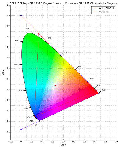
The reason for unreal primaries is that they are necessary in order to code all colours within the CIE “horseshoe” using only positive values. The AP0 primaries form the smallest possible triangle which contains all the real colours. This has the knock-on effect that a significant proportion of code values are “wasted” on unreal colours.

The AP1 primaries are a compromise which code most (not all – see other threads here on artefacts caused by negative values) colours likely to occur in images from real cameras using positive values. Because even the most saturated ACEScc/ACEScct/ACEScg colours are still real, this means that the maths of grading operations works in a way which “feels” better to colourists.

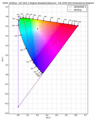
It may also be worth noting that the CIExy plot is not perceptually uniform, so the amount of green “left out” of ACEScg is not as significant as it might appear. A CIE u’v’ plot gives a different impression.

CIE plots generated using Colour Science for Python

3 Likes

Actually, AP1 primaries are also outside the spectrum locus, which makes them physically unrealizable (“virtual”).

Keep in mind that both AP0 and AP1 are just a definition of the colorimetric encoding. The encoding tells you what the numbers in the files represent - think of it as the legend or key to decipher the bits in a file back to something meaningful (colorimetry). It’s just math.

The decision about where to place primaries usually comes down to encoding efficiency. As @nick mentioned, the AP0 primaries enclose the entire spectrum locus but “waste” a lot of space for physically unrealizable colors. Keep in mind that if we have negative numbers available to us, we can encode values “outside the primary triangle” too.

Any set of primaries could be used to encode, but it really comes down to what is the most efficient for the colors one is likely to encounter. In the ACES spec, which uses AP0 we use 16-bit half float so we can encode positive and negative numbers at a pretty high precision and can “get away with” the inefficient triangle enclosure. If we only had 8-bit positive values, it would be much more important to have a tightly enclosed triangle around the region of colors we most care about.

Sometimes, negative values can also interfere with math operations such as those found in visual effects. This is part of the reason why alternate primaries, AP1, were established for ACEScg.

2 Likes

AP1 was designed to produce more reasonable ‘RGB’ grading (so that the dials move in the direction of R and G and B), to pick up critical yellows and golds along the spectral locus (to get that entire edge of the locus), and to clearly encompass Rec.2020 primaries by just a small amount. (in addition to the other comments above). Getting rid of the negative blue primary location in AP0 was also a goal.

1 Like

Thank you all for replying. I’ve had my suspicions about it but you all were able to explain it and make it clear.

I still have a few questions though.
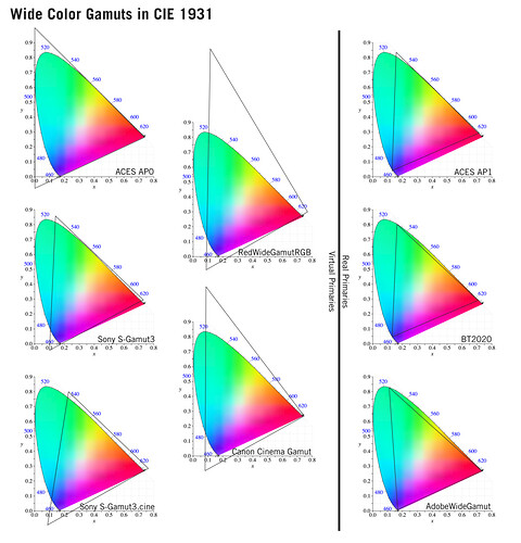
According to this picture i found in the mysterybox blog most camera manufacturers uses really wild primaries especially red and canon… Are those created because the physicality of the camera and because the internals require that to render color in an accurate manner?


Source: https://www.mysterybox.us/blog/2017/11/08/multi-space-color-correction

Also can you generally say the wider the gamut is the more bitdepth you need to display the colors without creating banding artifacts?

The primaries in cameras are for the Encoding of colors that come off the sensor. Encoded colors that can be expressed as a combination of the three primaries chosen. Sensors do not have primaries. Film did not have them either. Sensors and film are sensitive to certain spectra, and the regions of light where they are sensitive overlap. You can enclose a region with a triangle, but not all regions in that triangle are active. With silicon sensors, colors can be sensitive to non-visible colors as well, even when the design is only for visible light. So when deciding to cover a range of spectra, a camera color encoding is designed to get the best overall accuracy over a region given other design constraints. All of these are reasons that different camera makers can optimize their color encoding differently. The other part of the equation is that the CIE Spectral Locus is just a MAP – and recall the saying, the map is not the territory. It is even a twisted map, because perceptually the Diagram doesn’t even correctly represent how people see combinations of colors. People actually see with enough variation that the spectral locus is really more of a fuzzy boundary. So it also makes sense to encode colors a bit beyond the boundary. Hope this helps – Camera design is as much Art as it is Engineering.

4 Likes

Non-linear RGB math operations will inevitably cause hue shifts outside of white\gray (the middle point of the triangle). Easy to conceptualize in your head, if you have RGB [0.1, 0.1, 0.1] no RGB math operation will result in a number different from RGB[X,X,X]. That means there will be no hue shift. Canon and Red shift their white point towards skin tones so that grading operations are less likely to manipulate skin tones.

Conversely imaginary primaries like AP0, RedWideGammut and Canon all cause problems with physical simulations of light like 3D rendering in VFX. In AP1 or Rec2020 imagine you have a pure green wall that is 50% reflective. That means you want a white photon with an “energy of 100%” to be represented as RGB[1.0,1.0,1.0]. It hits your pure green 50% absorbent wall RGB[0.0, 0.5, 0.0] and you multiply to simulate absorbtion and reflectance. And you end up with RGB[1.0,1.0,1.0] light * RGB[0.0, 0.5, 0.0] wall = RGB[0.0, 0.5, 0.0] Let’s say it bounces 2 more times. We just multiply by the wall’s color 2 more times. You end up with RGB[0.0, 0.125, 0.0] light. It reflected green exclusively and absorbed all of the red and blue. 3 bounces of 50% absorbant walls resulted in what you would expect 0.5^3 = 12.5% of the original light.

AP0 messes this up. Your same 50%, pure green wall (pure 530nm wavelength) in AP0 is RGB[0.07, 0.42, 0.01]. Multiply by “white” light and we get RGB[0.07, 0.42, 0.01]. Multiply 2 more bounces and we’re at RGB[0.00044, 0.07, 0.0000002]. When we convert that back into “real” AP1 primaries we’re at RGB[-0.02, 0.09, -0.002] or 9% of the original light. Because full saturation primaries aren’t actually a ratio of wavelengths you end up with 25% less light than you should have by doing the operations in an imaginary color space. Also you end up with negative red and negative blue values. There is no such thing as “negative” filtration in the physical world so we just clamp those before they cause problems. It’s created a color that is more pure than a hypothetical pure laser light source. An infinite stack of color filters can’t create a light more pure than single wavelength of light.

“Energy Conservation” is an important concept in 3D rendering. If you emit 10,000 lumens of light into a scene, you want the materials to absorb or reflect 10,000 lumens of light. When you have imaginary primaries as demonstrated above, you easily get into situations where at best you losing energy. That leads people to be tempted to start cheating reflectance values higher in their shaders and breaking the physicality of the scene.
2 Likes

Hi Gavin,

I had to think about this one a bit… and I checked your math. I even reran it in AP1 to see what happened and your numbers are still close. (-0.182, 0.09338, -.00004762)

So lets take the new RGB (0.07, 0.429, 0.01). When you are doing the light calculations, if you treat
absorption as a spectral quantity that will have a different value in a different color space – OR – you can assume a (.5,.5,.5) across the whole spectrum as the absorbance factor. So if you do that, after 3 total bounces, you have a (0.018, 0.107, 0.003). When you then convert from ACES to Rec2020 you get (0,0.125,0) the same as in your previous paragraph. So the math gets to the same result when you assume
a 50% absorbance across the entire spectrum and each step is cut in half.

But I can’t quite see what is happening with the monochromatic absorption factor (007, 0.4298, 0.002)AP1
. The math looks right and it reduces as you say, but I am wondering if there is an assumption in there that throws things off. I will have to think about this some more.

I believe the ‘problem’ is fundamental with the model.

As a thought experiment start not with 3 channels but say N channels, under any condition other than all of them being exactly equal, after each step of absorption e.g. light bouncing off surfaces, or passing through a medium, some of the channels will be reduced more than the others. Clearly the one(s) which have the maximum value in the absorbing medium to start will continue to be the largest and over each step/iteration will be come more and more dominant relative to the others. (Assuming your initial light contains energy in those channels).

In the limit of precision you end up with only those channels (probably only one channel) having any value, thus you end up with a “pure” colour but at reduced intensity.

This doesn’t matter if you use 10nm block colours or 1nm or some other spectral power distribution to compute your channels, you will always drift towards the basis used in the computation.

Kevin