as asked by @carolalynn, I create this post to share some of my results on Gamut Mapping. I would like to show my small contribution to this beautiful project. We have implemented ACES at our studio and we love the results we get from it. During its integration, we were faced with the ODT clipping “limitation” and this is why I have been following this group’s work with much interest. Our movies are notoriously quite saturated and Gamut Mapping may be an essential part of our color workflow for our next productions.
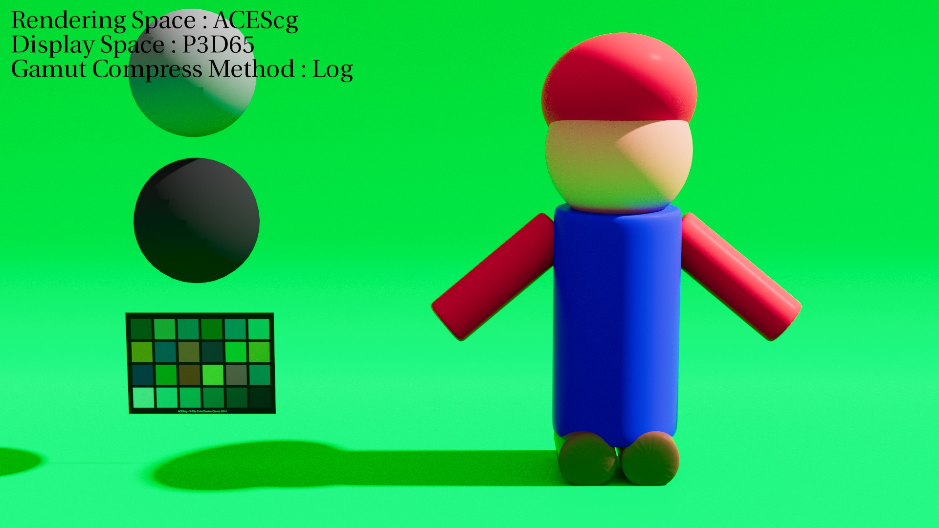
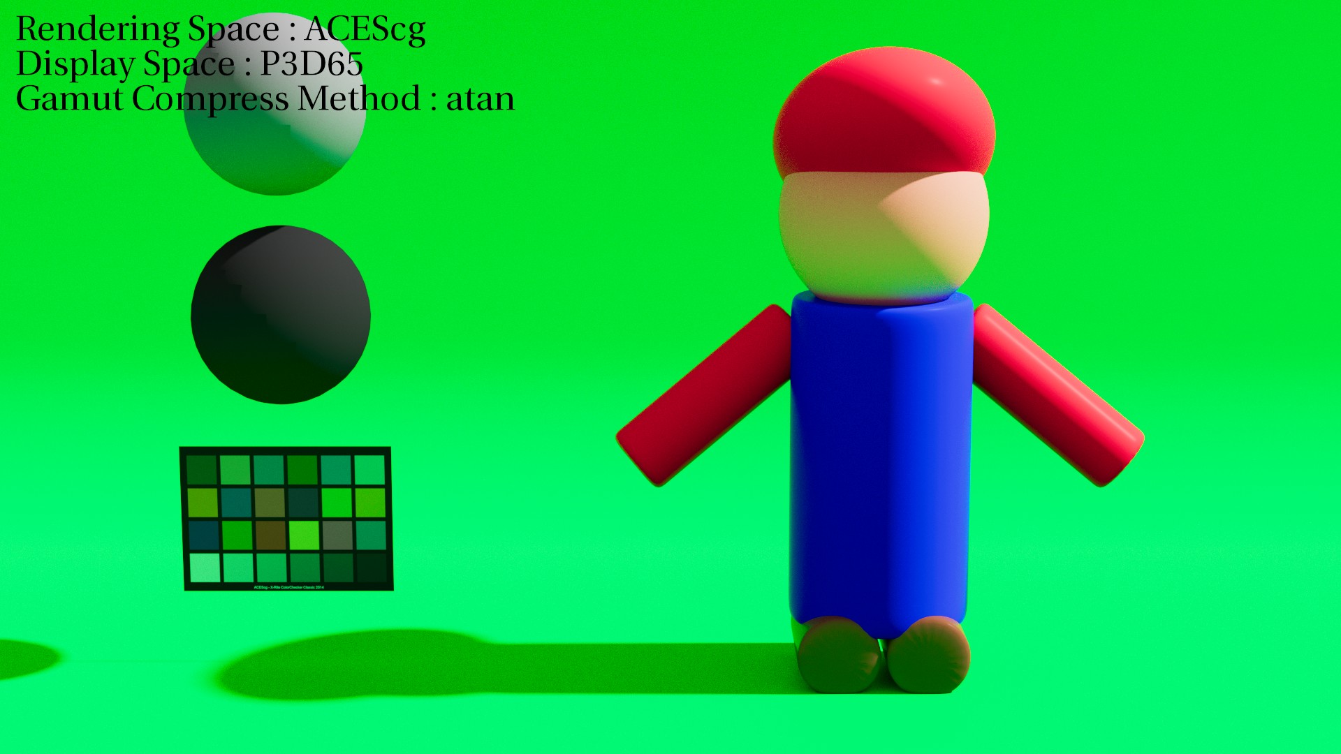
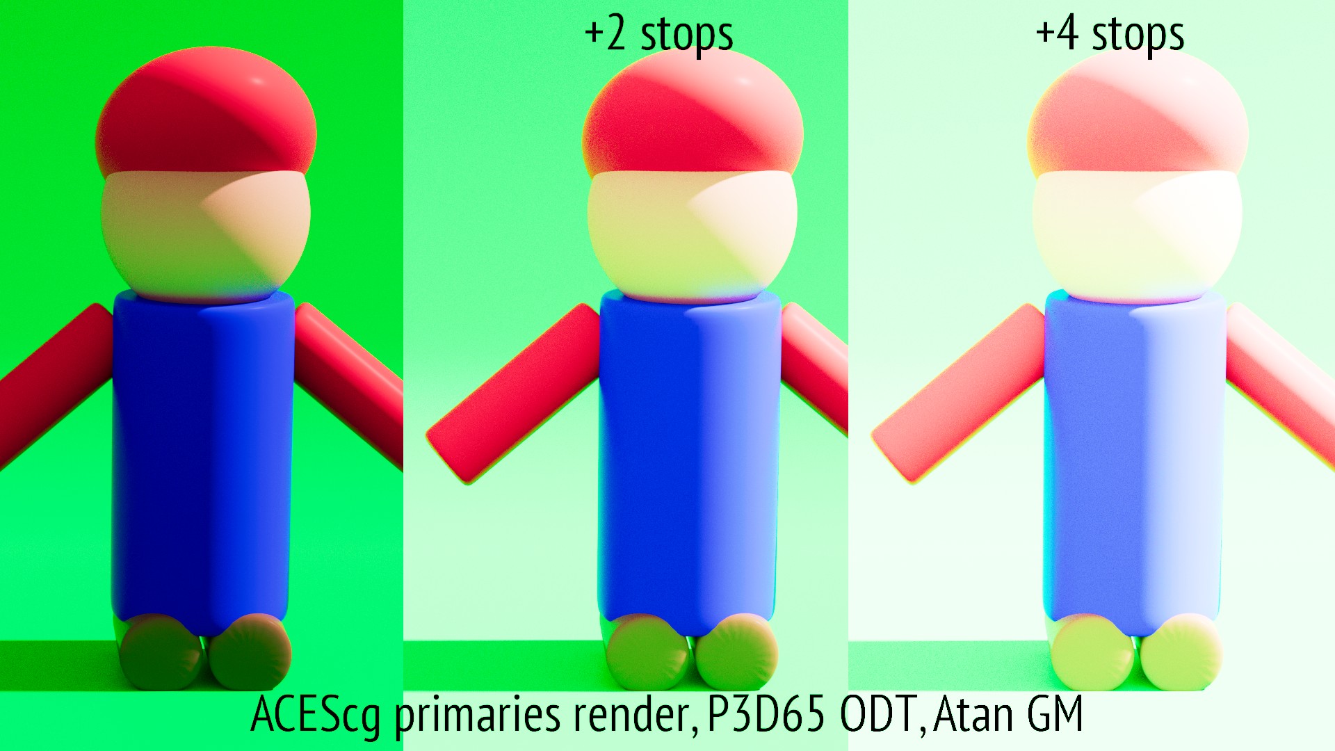
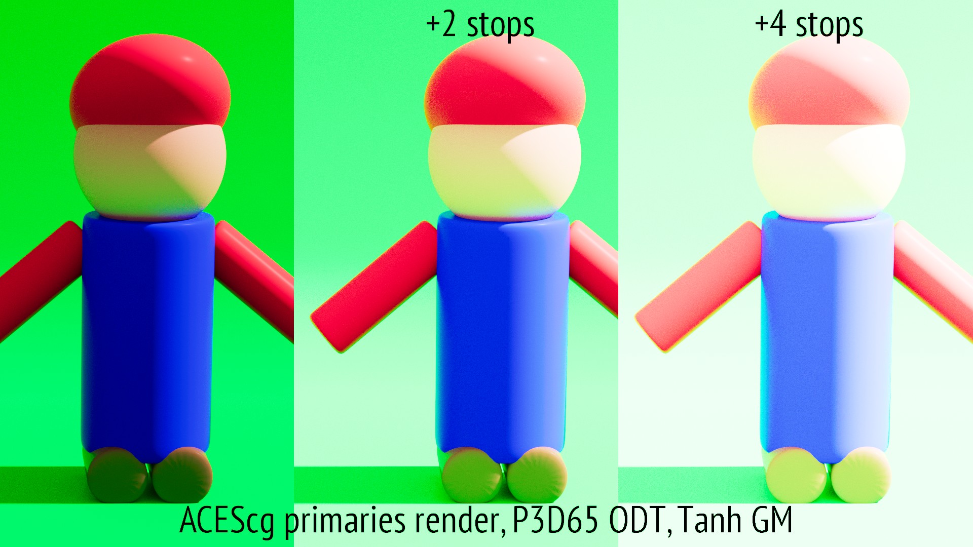
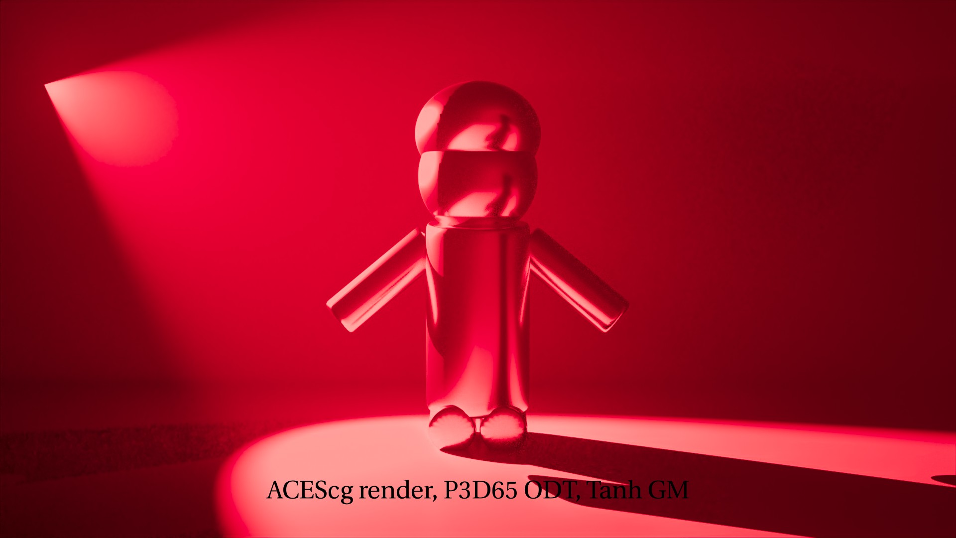
All renders are in ACEScg and displayed using the P3D65 (ACES) ODT from the ACES 1.1 OCIO config (the standard P3D65 48nits ODT, intended for a 2.6 gamma display).
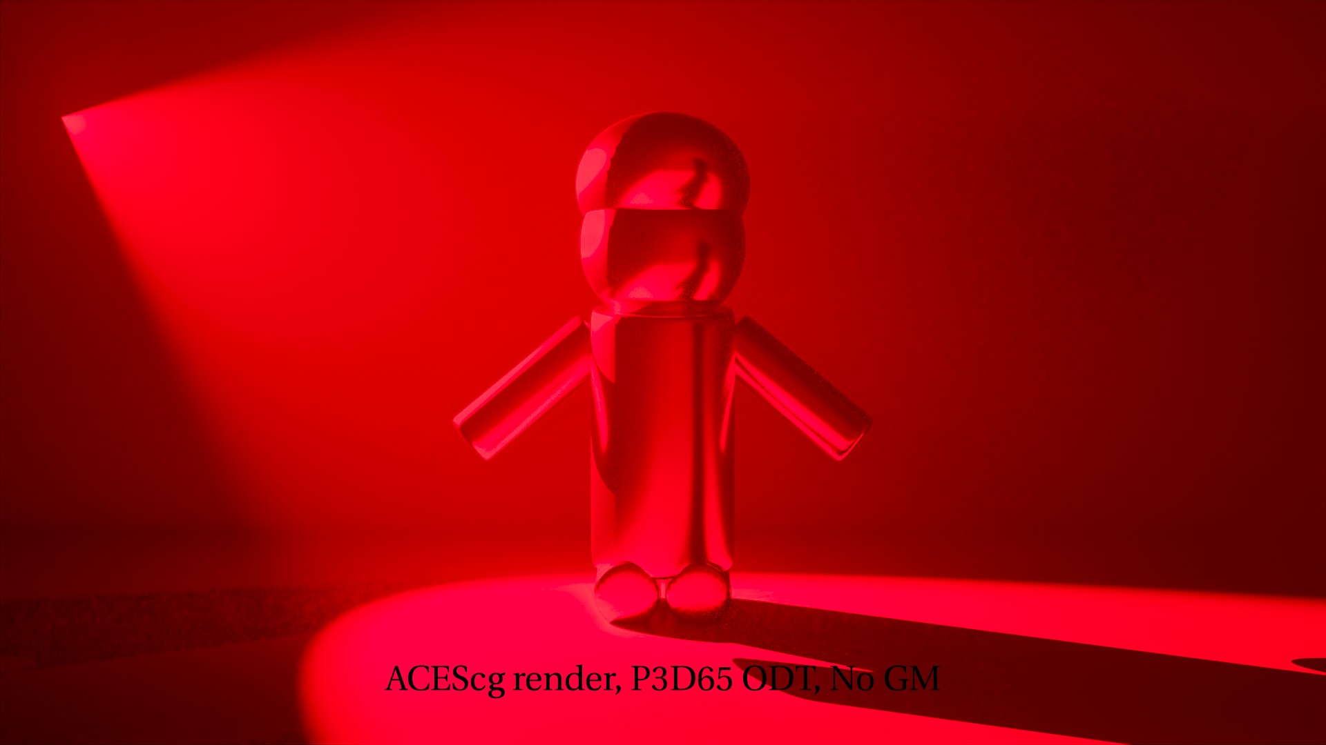
The basic render with no Gamut Compress method. I have used Guerilla Render for these tests.
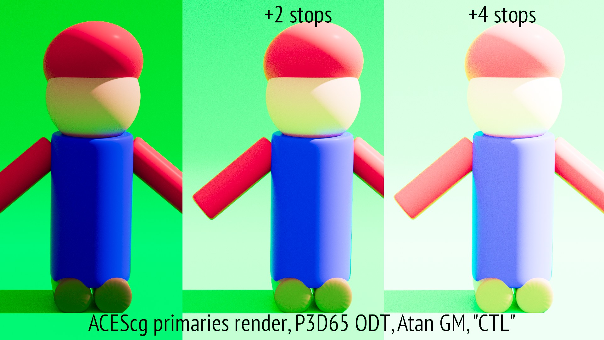
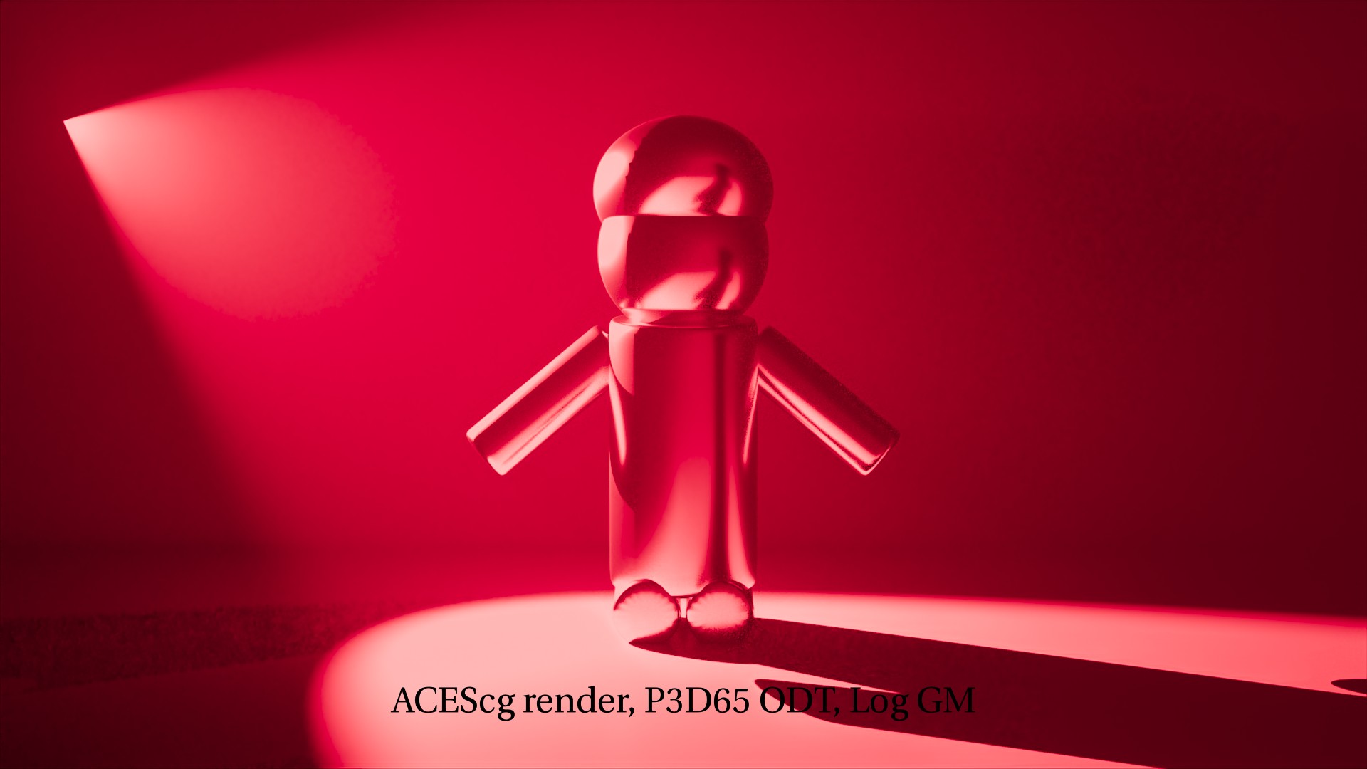
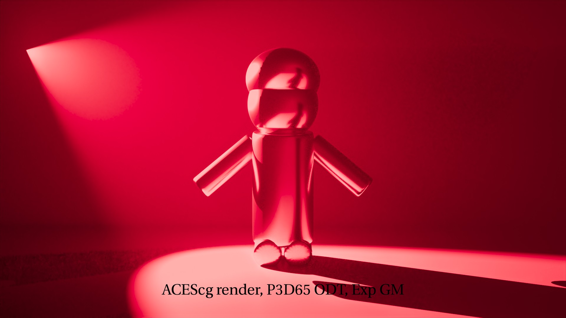
I have to say I am pretty much pleased with the Tanh method, it will probably save many issues on our end (even if the method is still being discussed). I would also love to do more tests on different renders (probably an ACEScg red primary light being reflected in a mirror or going through a volumetric).
A couple of things I would like to mention that may be interesting :
The VWG is focusing on putting scene-referred values that are outside AP1 back into AP1 .
Knowing this I was surprised to see any improvements on my renders since they are ACEScg renders with no negative pixels.
Fortunately Nick Shaw gave me this great explanation :
That compression protects the middle 80% (by default) of the AP1 gamut, and then compresses out of gamut colours into the remaining 20%. Therefore by definition some of the colours which are near the gamut boundary have to be squeezed in, to make room for the out of gamut colours. Same reason diffuse white can’t be at 1.0 on output, or there would be no room to compress highlights.
Pretty much comparable to a sound compressor, if you want it to work you need to have some headroom to compress in the first place. Using the same analogy, we’re trying to find a basic way to compress the signal using multiple frequency bands instead of all at once (hence preserved colors inside the middle 80%), while avoiding harmonic distorsion when things getting squashed, as in mastering comp.
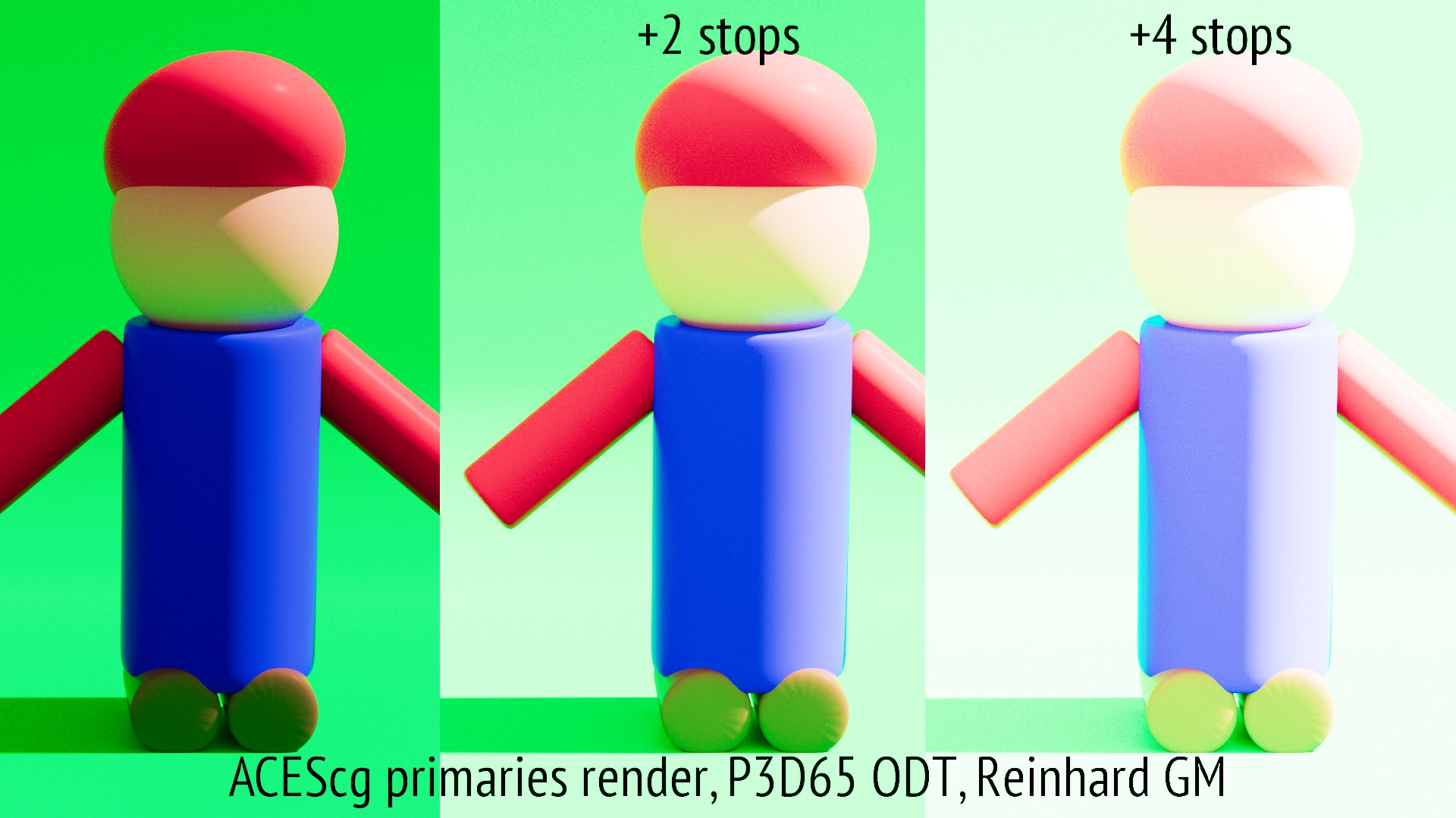
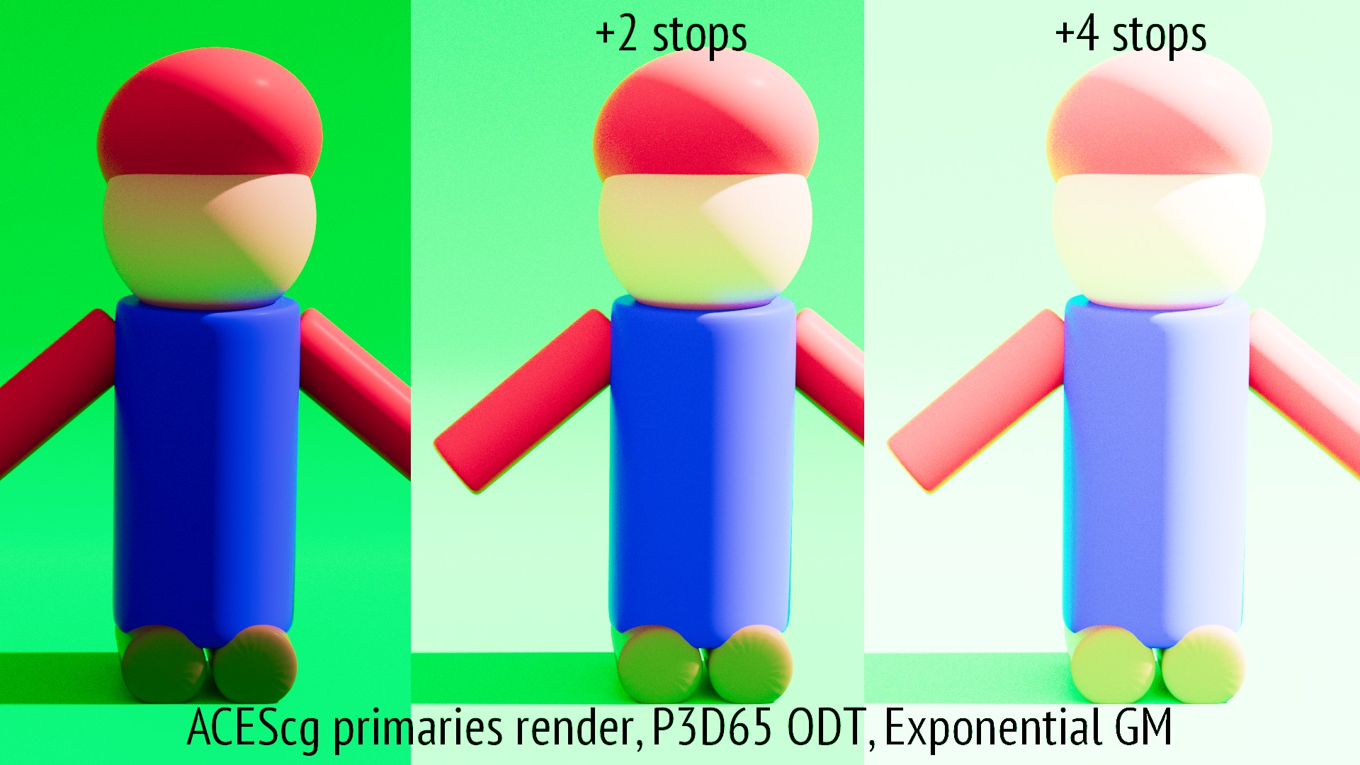
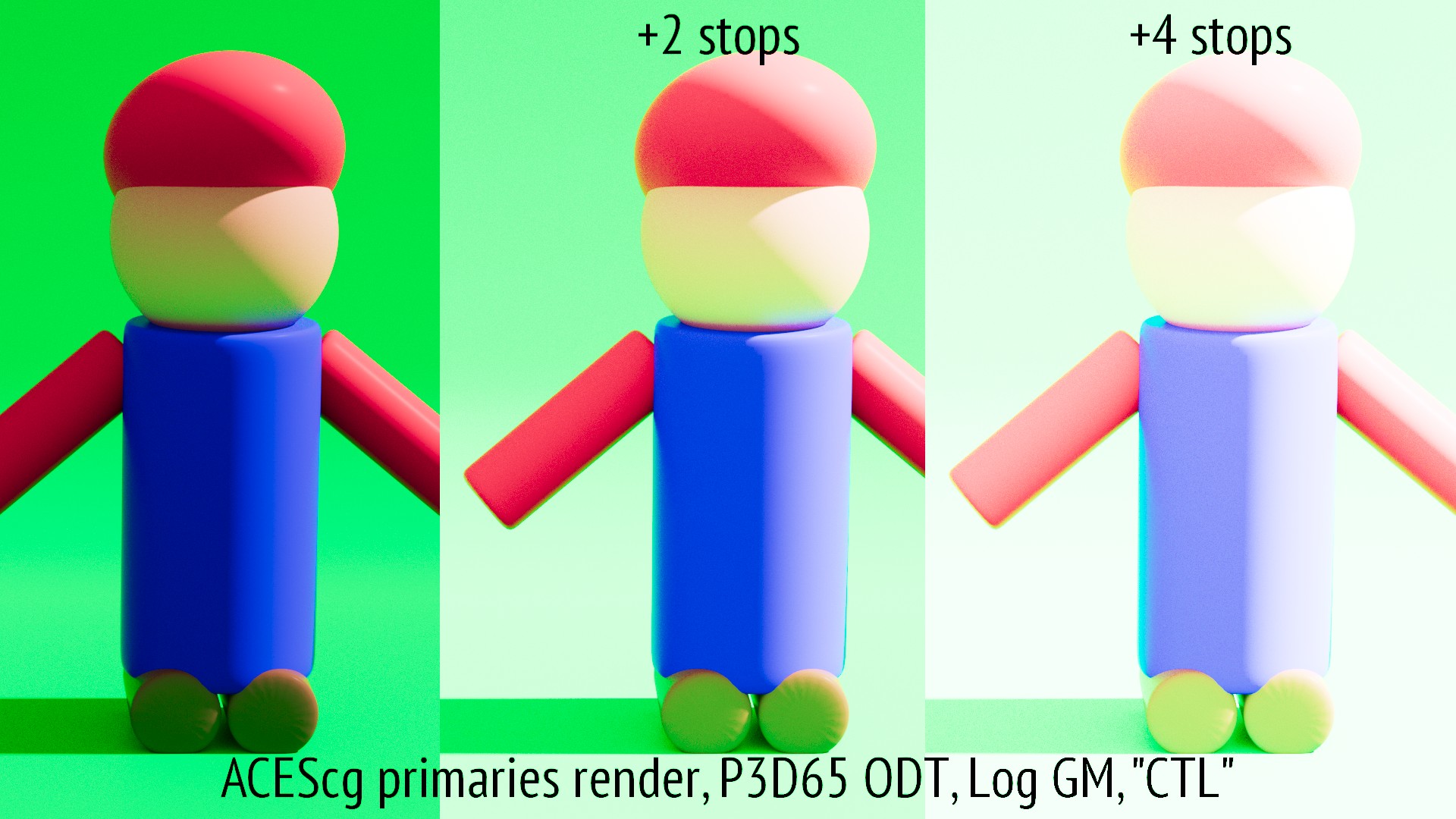
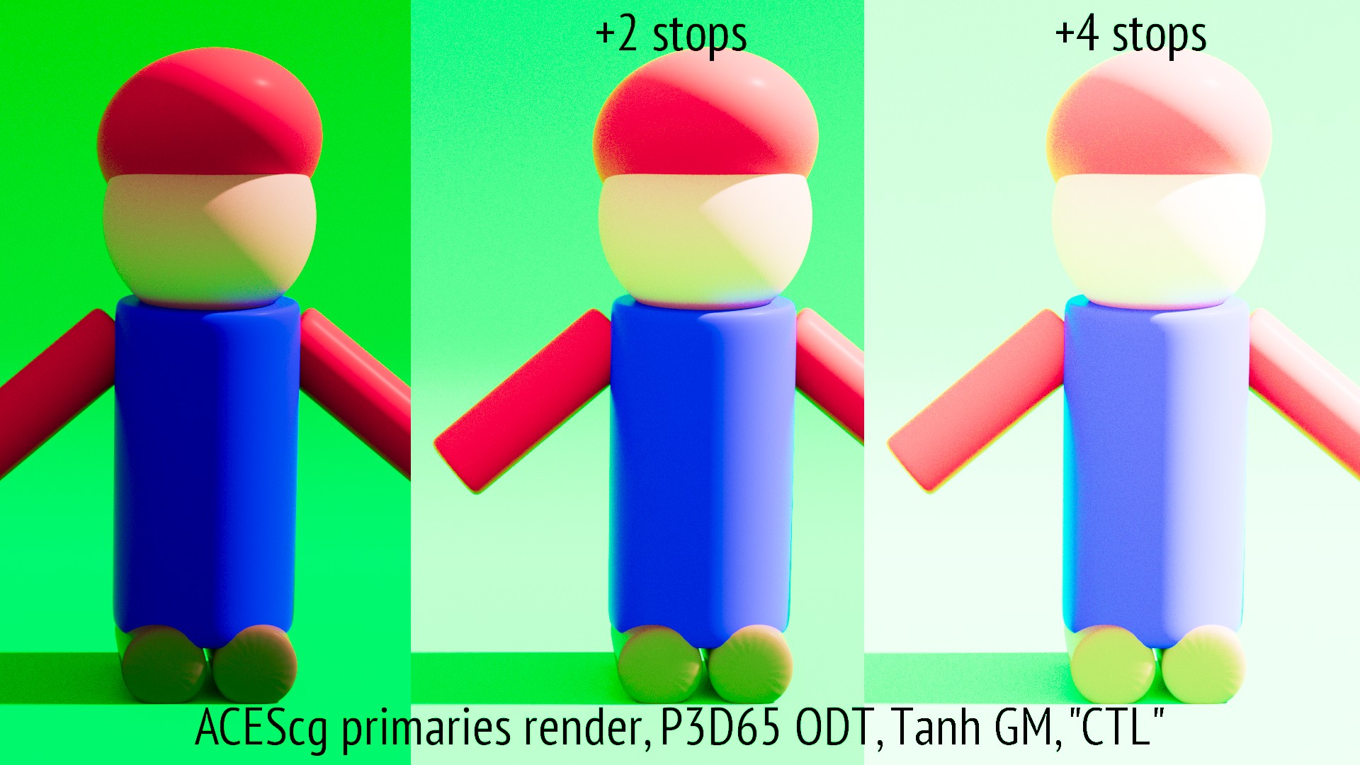
This is a good test image for the idea of an ODT placeholder gamut volume mapping as per @daniele.
Note the wild hue skews, especially the cyan on the sides and the yellow on the head, amongst other examples. Even the flat red of the hat is posterizing due to the volume limit it would seem.
Something to keep in mind here is that (correct me if I’m wrong @ChrisBrejon) but those images are processed in Nuke with OCIO right? So they might also be subject to limitations of the LUTs backend. We should process them with CTL to be certain of what we are looking at.
In terms of the 80%, a majority of the contact is via OCIO, so regardless, the gamut map placeholder should work properly on the OCIO distribution I’d think?
Even given an unlimited transfer function, the result would still be wrong anyways. So be there gamut clipping on volume or not, a gamut map is still required simply to not generate cognitive dissonance. Example: A pure saturated primary of increasing intensity should not terminate at a purely saturated primary output.
Thanks guys ! Your’re totally right @Thomas_Mansencal, these images have been processed in Nuke with OCIO. I could try to process them in CTL (using Nick’s nodes or even Resolve I guess).
And yes these renders are out of topic. I realized that during the VWG meeting yesterday. Since this group is focused on finding the best algorithm for OOG values, it does not apply on these frames. Nonetheless I thought it was interesting to test the nodes and compare the results. I was curious on why my renders were benefiting from the GM and at least now I know why !
And I’d be more than happy to tag/attach this post and these renders to the future VWG of ODT GM.
You are using the gamut mapper here in a slightly different way than intended, since your image is already within AP1. Nonetheless it is a valid test of the algorithm, as it is important to know that images which are in gamut for AP1 are not degraded in an undesirable way when processed through it.
I had a look at Resolve this weekend for the CTL tests. I thought I could compare every algorithm/function to the OCIO version but could not find the parameters in the CTL node.
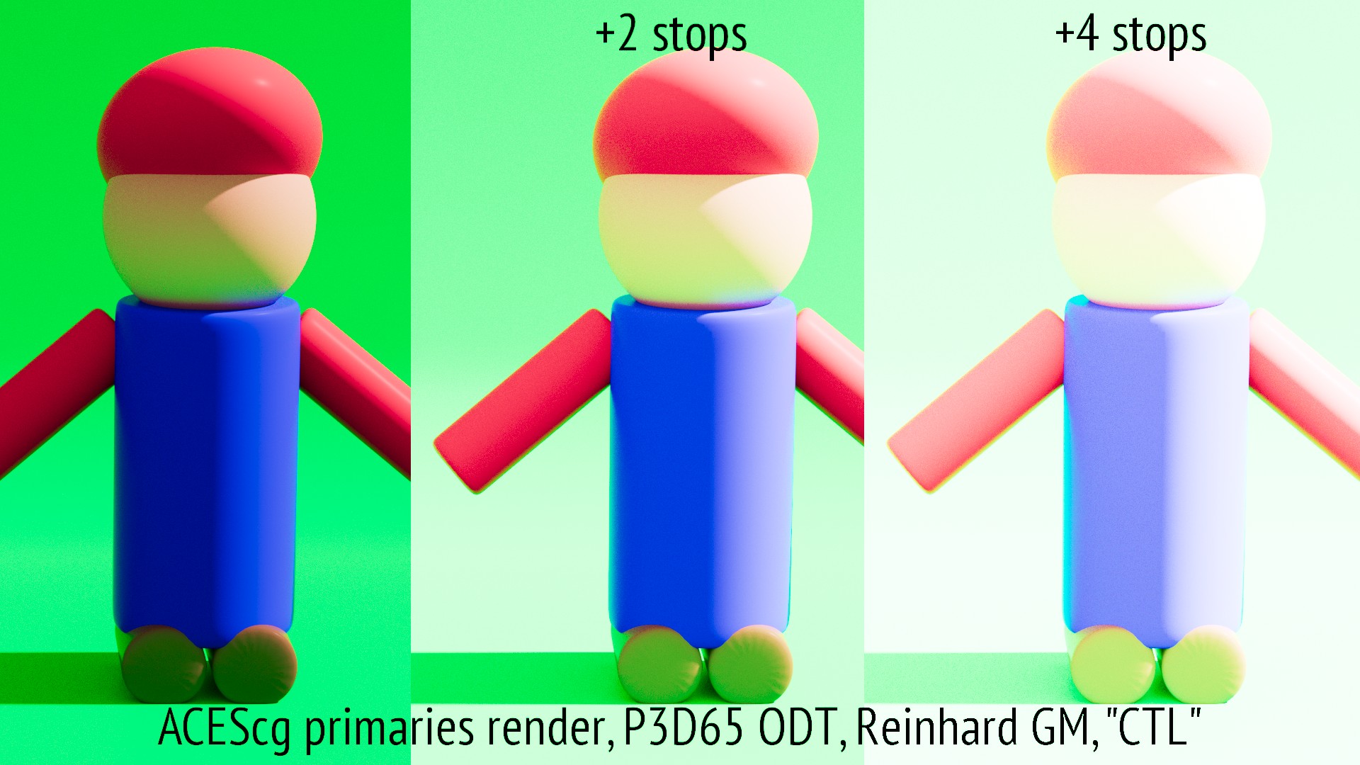
I haven’t looked in detail, but I believe that @jedsmith’s release DCTL only implements Reinhard, because the others require an iterative solve for finding the intersection of the curve with 1.0. BlinkScript can run that solve once (in the init() function) and then apply the resulting parameter to every pixel. DCTL (and Matchbox AFAIK) are a single shader which runs for every pixel. That is obviously very inefficient for a solve which is the same every time.
But I think one of the versions in @jed’s repo does sacrifice efficiency in order to include all methods. You will just need to find the right one.
sorry for the late reply. I had a look at Jed’s repository but could not find any dctl with all the algorithms. I carefully had a look at the comments and downloaded four different versions but was unlucky. So I decided to go another route (my free version of Resolve does not allow me to use dctl anyway and I got a big watermark on top of the image).
So I remembered Alex Fry’s Pure Nuke Implementation of ACES that was updated by Nick later on. Is this accurate enough for our tests ? I hope so. The only OCIO conversion used in my setup is from AP1 to AP0 since the Nuke’s nodes need AP0 as an input. Does it bias the tests ? I’m not sure…
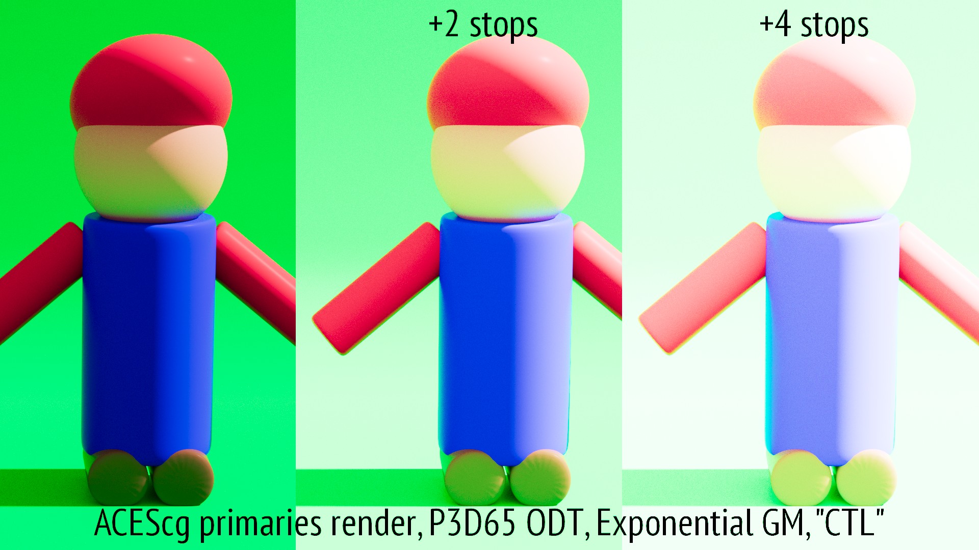
I have put CTL between quotation marks so there is no confusion since I am using a pure Nuke implementation of the RRT/ODT process that should match at 100% the CTL code. Let me know if all of this unclear/useless/incomplete @nick . I am happy to provide more tests.
Update : These images have been processed with an old version of the Nuke nodes and should not be considered 100% accurate. Apologies for the trouble.
An AP1 to AP0 conversion with OCIO uses a matrix, not a LUT, so it is mathematically exact, and will introduce no artefacts.
I would recommend you use @alexfry’s repo for Pure Nuke ACES, not my fork. I never got round to updating anything after I forked it, and he has updated his since.
Thanks for the heads-up ! It seems that the previous version of the nodes I was using had an Adaptated White Point option on the ODT that is not currently available in the latest Alex’s publish. I will try to re-generate the frames using his latest publish. Meanwhile I have done some new tests.
Spot light has an ACES primary red (1/0/0), the floor is a midgray shader (0.18) and the character is metallic (rendered in Guerilla Render).
I have noticed that differences between OCIO and CTL are quite insignifcant after GM. All these images have been processed using the latest build of the Nuke nodes from Alex Fry’s GitHub. Apart of the hue shift, I am quite happy with the results.
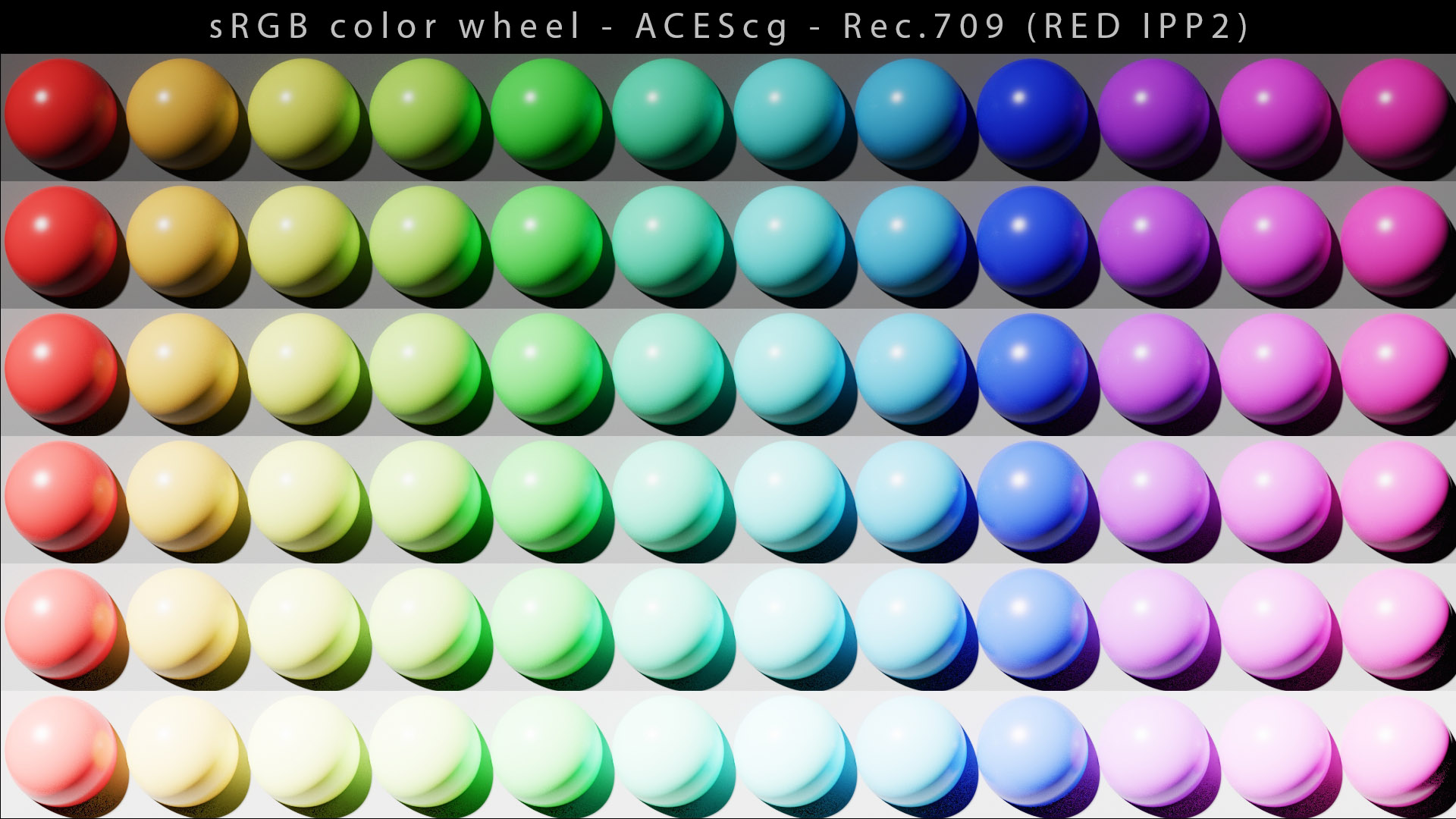
sorry for reviving this old thread but after the last GM meeting (2020/09/10), I wanted to do some quick tests using the GM OCIO config and the latest version of the algorithm.
I know that my ACEScg renders are only benefiting from the algorithm as a side effect, like a cheat. But since they were talks of testing the algorithm with objective/subjective comparisons, here I am.
I completely understand that this GM algorithm has a scene-referred purpose and the improvements I may see only come from the fact that I am scaling/compressing the working space, ACEScg.
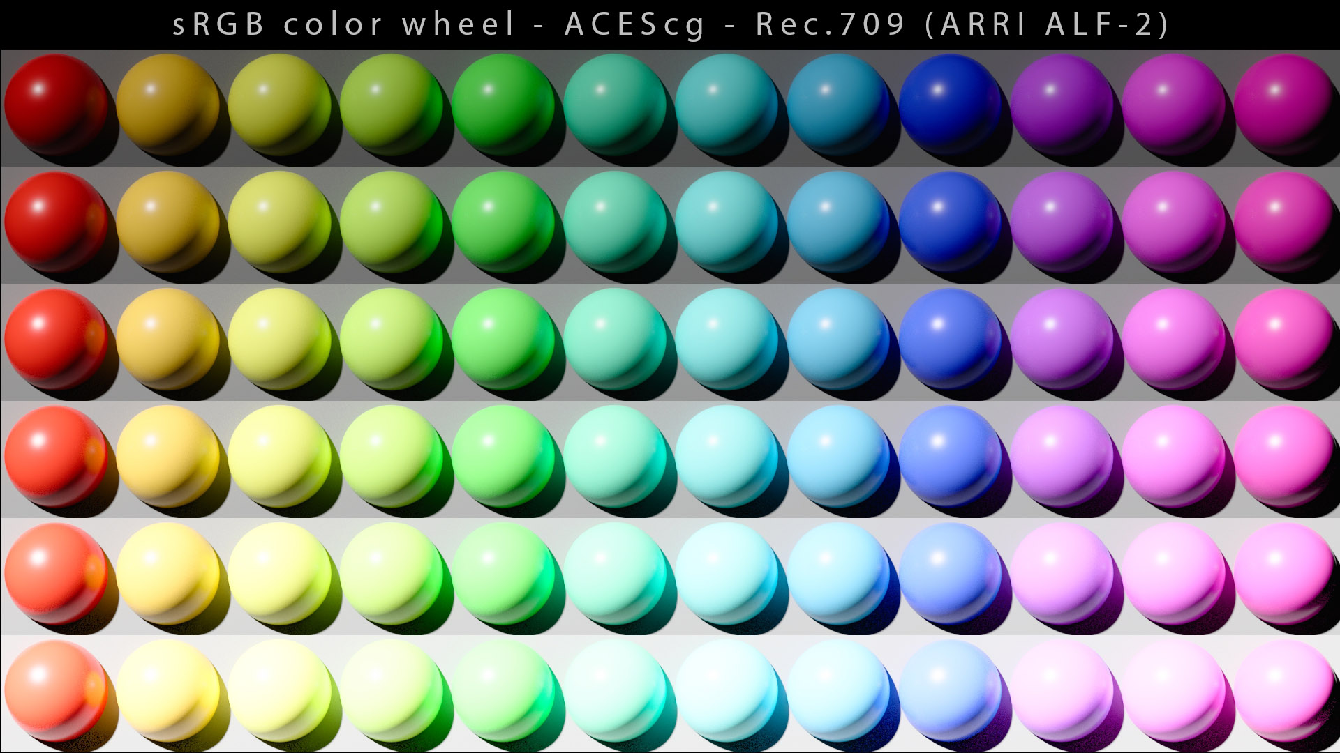
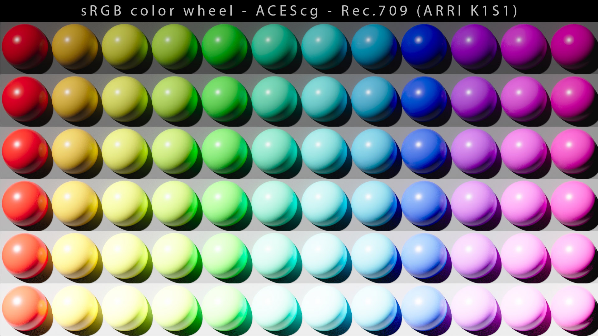
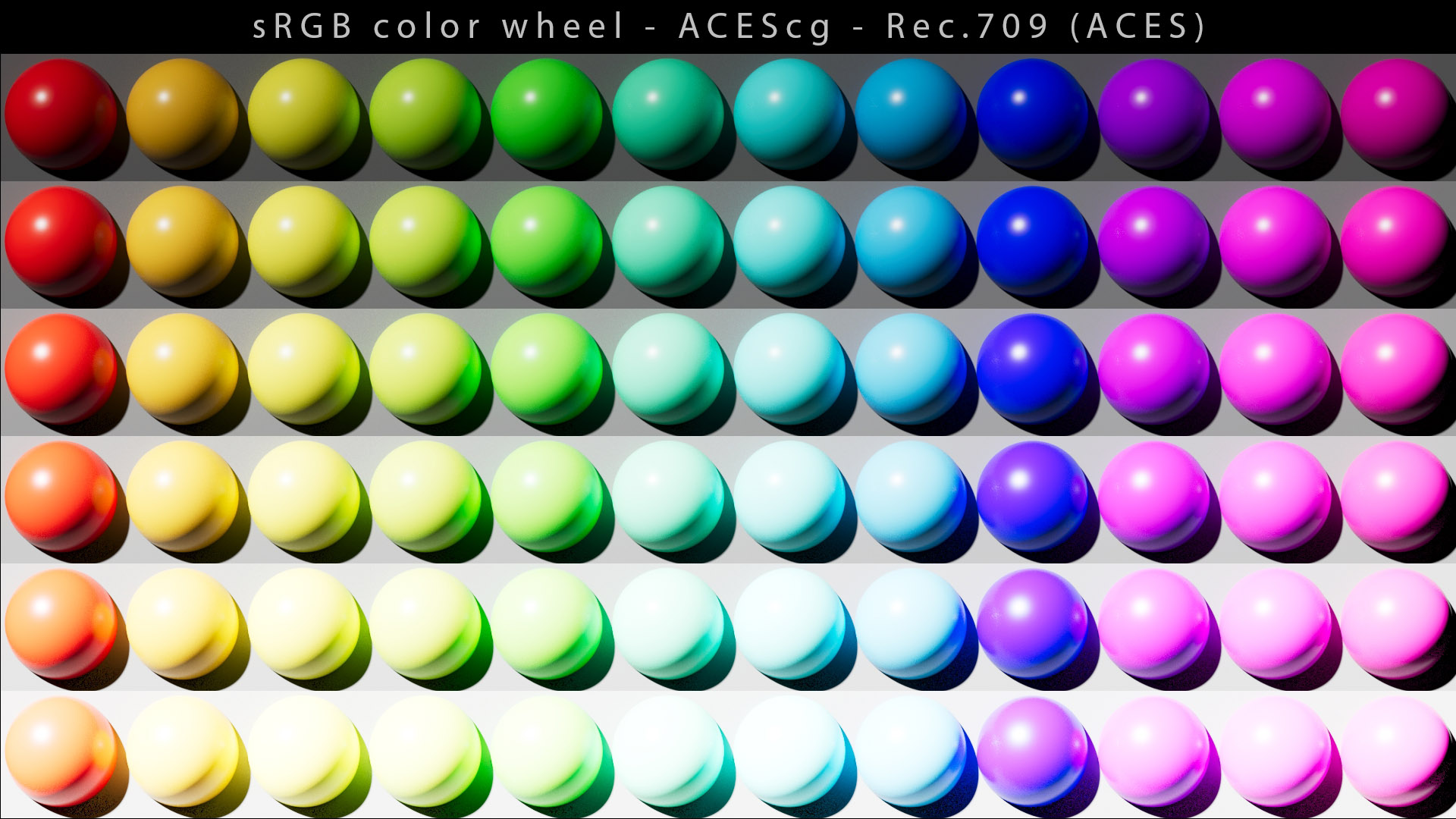
What interested me were the improvements on the blue spheres and red spheres with the ACES default ODTs. I have used sRGB primaries for the test and the algorithm by default :
threshold (0.815, 0.803, 0.88)
power 1.2
cyan 0.147
magenta 0.264
yellow 0.312
These tests were fun to do even if they are probably pointless. Happy rendering !
Chris
I actually have to give you many thanks for that since I wanted to compare all those DRTs with an objective metric. I only need one more which is a modified ACES 1.2 workflow that uses the SSTS for sRGB output and does the blue highlight fix in the same way Unreal Engine 4 does it (60% blend with original then invert it before conversion to display primaries [blended at 60% too]). I believe you posted the original .exr you used for those spheres somewhere on this forum right?