Just to summarize, I’m a 3d CGI sup/artist in a french studio and I’ve been watching/learning ACES for about two years now.
I think I’m pretty much used to it and planning to “teach” it to my colleagues soon.
As I don’t want to spread false or approximate infos, could anyone help me confirm or correct what I’m about to tell about LMT, RRT and ODT ?
I saw here and there some infos about it, but it still feels blurry in my mind…
Let’s start with the RRT/ODT :
First I read that there’s a “primaries” conversion to AP-0 gamut (by the way is it just a primaries conversion, or a full colorspace conversion as data may come from ACEScg or ACEScc/cct ?)
Then, I’ve heard of a shaper curve. Kind of a “log” transfer curve applied to fit HDR datas into a 0-1 range. (is this step dependant on the ODT ? is the curve the same for SDR and HDR ODT ?)
Then, a S-shape curve is applied (by the way is it applied on all R,G,B channels equally ?)
Finally, the ODT remaps the primaries to the output/display colorspace (is a transfer curve still necessary at this point ? eg. for sRGB output, is the sRGB transfer curve applied too ?)
Second point is about LMT :
I’m not very familiar with this step as I don’t really understand where it takes place ? If i’m not wrong, it is some kind of LUT that you apply on ACES data to give a look before the RRT/ODT. Then how do we generate this LUT, in what software, to what format, and then how do we apply it ?
Feel free to correct any word that I misuse as I think terminology is the key when working with ACES…
Of course this is a kind of subject that may have been talked in other topics, but to be honnest, I really never found a clear, precise and reliable one about this. It’s always like fishing infos here and there, and at the end, there’s still missing puzzle pieces… ^^
From what I have seen, LMT are not fully implemented in softwares and you’ll probably need to edit yourself the OCIO Config to implement them. I have tried in the past and it is a bit tricky.
Again, thanks a lot for your answers. However, these documents/articles sum up exactly what makes my mind still blurry.
I’m no dev and not willing to track down every function/method in external modules and I thought maybe one or two orginal contributor could put a bit of words over this (even if comments in the CTL do give hints) .
Of course I’m not asking for every details, but for the main operations that happen.
It is probably easiest to think of the RRT/ODT as combining to produce a single Output Transform. The fact that it consists of two parts is not really relevant to the end user, and not the way it will be in the long term (the HDR Output transforms are already single stage).
Broadly an Output Transform consists of:
A transform to linear AP1 (taking account of the current colour space, which will be ACEScg for VFX, ACEScct for DI or ACES2065-1 for unmodified ACES image data).
A tone curve to map the range between black and a particular ACES value (16.29 for SDR Output transforms, but HDR OTs use a higher value, which varies with the peak luminance of the target display) to the display luminance range.
A couple of “sweetener” operations (red modifier and global desaturation) which tweak the appearance of the final image.
Surround compensation, if required. This is a gamma adjustment which compensates for the difference in perceived contrast between an image viewed in a dark cinema environment and a dim video viewing environment.
A transform to the primaries of the target display.
Encoding with the inverse EOTF of the target display, including mapping to the 0-1 range.
Regarding LMTs, conceptually any grade which is applied across an entire scene or show, downstream of the per shot grade but before the Output Transform, is an LMT. In theory such a grade should be exported as a CLF LUT to be a true LMT but since, as @ChrisBrejon said, tools don’t exist to interactively create a CLF LMT with tools familiar to colourists. So a LUT exported of a grade which can be applied to ACEScct data, and which produces modified ACEScct data is the simplest form of LMT. Otherwise, a colourist and colour scientist need to work together to convert a grade into a CLF, which will be something of a manual process.
The RRT expects ACES2065-1, and only ACES2065-1, as input.
It is the responsibility of the user or software to do any necessary conversions into that encoding. This might be via an Input Transform from a particular camera log encoding and primaries or could be a color space conversion from ACEScct (e.g. in a color corrector, the data in the grading stack or node tree which is usually ACEScct, must be converted back to ACES2065-1 (i.e. linear AP0) before applying the RRT.
EDIT: What @nick was referring to in his Step 1 was about the processing steps that happen inside of the RRT. However, the RRT does not take into account the current color space that is going into the transform - that is the role of the color corrector or user to apply a simple transforms to switch data back to the AP0 and linear that the RRT expects. I hope that makes sense.
Thanks a lot Nick and Scott, these answers will be of good help, especially next to the ctl code.
Sorry to insist about this last point : If I understand well your explanation about this step 1, what is supposed to “enter” the RRT is ACES2065-1.
Let’s take the example of maya or nuke etc… where we already work in ACEScg. What you mean is that the software is already configured to transform AP1 to AP0 before sending it to the RRT/ODT ? (is it the OCIO that handle that step ?)
What you need to be clear on is the difference between what the RRT as specified does, and what the user sees in an ACES implementation. The RRT is never exposed directly to the user, and is a building block of an ACES Output Transform, used by implementers when building their ACES implementation.
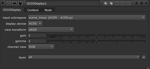
Both Nuke and Maya use OCIO to implement ACES. The ACES OCIO config defines, for example, the Output - sRGB (ACES) “colour space” in terms of a series of transforms from the reference colour space, which is ACES2065-1. OCIO handles the conversion from the working space (normally ACEScg) to the reference space automatically if your system is configured correctly. So when you select sRGB (ACES) in Nuke as the viewerProcess the OCIODisplay node is applied under the hood (you can “show pane” to see it) and is doing a conversion from ACEScg to ACES2065-1 followed by the RRT followed by the sRGB ODT.
In Resolve, you choose the working space (normally ACEScct) at a project level, and Resolve knows that it needs to convert from that to ACES2065-1 before applying the RRT and ODT. The user just selects from a list of Output Transforms.
Whether an implementation actually performs each operation in order as specified is irrelevant to the user, as long as the correct result is achieved. There are often optimisations which combine multiple transforms, or remove redundant ones where the last step of one transform is inverted by the first step of the next.
Thanks Nick for that last answer.
So that’s more or less what I guessed.
I think I have enough stuff now, I’d love to know more about the tone curves and how they are designed for the various display target, but it should be enough for now.
(Maybe you could just point me where I could dig in the code or get some reference documents ?)
All you can really do is read the CTL code. All the functions are there within the library – the ACES CTL is pretty self contained. But following it does mean jumping back and forth between the library files and the RRT and ODT code.
The HDR Output Transforms are slightly easier to follow, and they only include a single tone curve.
Your a legend for helping so many people across so many platforms so thank you for all your support and efforts. I have read many of your post on Lift/Gamma/Gain too
We are just getting into using ACES in our productions and admittingly, I only have a basic understand of it at this point but trying to learn as much as I can.
One question I have lead me to this thread…regarding and better understanding the RRT step:
From what I understand, all incoming sources/images must be transferred into to super wide ACES-2065-1 (uses APO primaries) space before coming into the color corrector. In our case, this will be based on using sRGB primaries in production (unfortunately not ACES CG at this time) delivered to our color corrector (Lustre) via an IDT. In the color corrector, we will work in ACEScc/cct (uses AP1 primaries). When done grading we will then need to render back out to ACES-2065-1 and apply the RRT/ODT for whichever deliverable we are releasing for.
I guess my question here is, does the RRT also use/reference the same AP1 primaries to sort of make sure the images are being processed in the absolute widest real world display “reference” gamut possible before the ODT? Or does this limiting/mapping of gamut happen only once in the ACES cc/cct step (since it too is only working in the AP1 primaries) when your grading in and the final RRT/ODT just maps those values to the appropriate output display where really just the "ODT part of the RRT/ODT combo xform is being applied
Mapping to ACEScc(t) for grading (or ACEScg for VFX) does not limit the gamut to AP1. It is simply that when encoded as AP1, the numerical values work better for the maths of grading and compositing operations. AP0 values outside the AP1 gamut simply become negative AP1 values.
There are of course occasions when negative values may be problematic, and it may be useful to compress or clip to AP1 (see the work of the Gamut Mapping VWG) but that is a choice, and not inherent in a transform to ACEScc(t) or ACEScg.
Clamping does happen later as part of the Output Transforms.