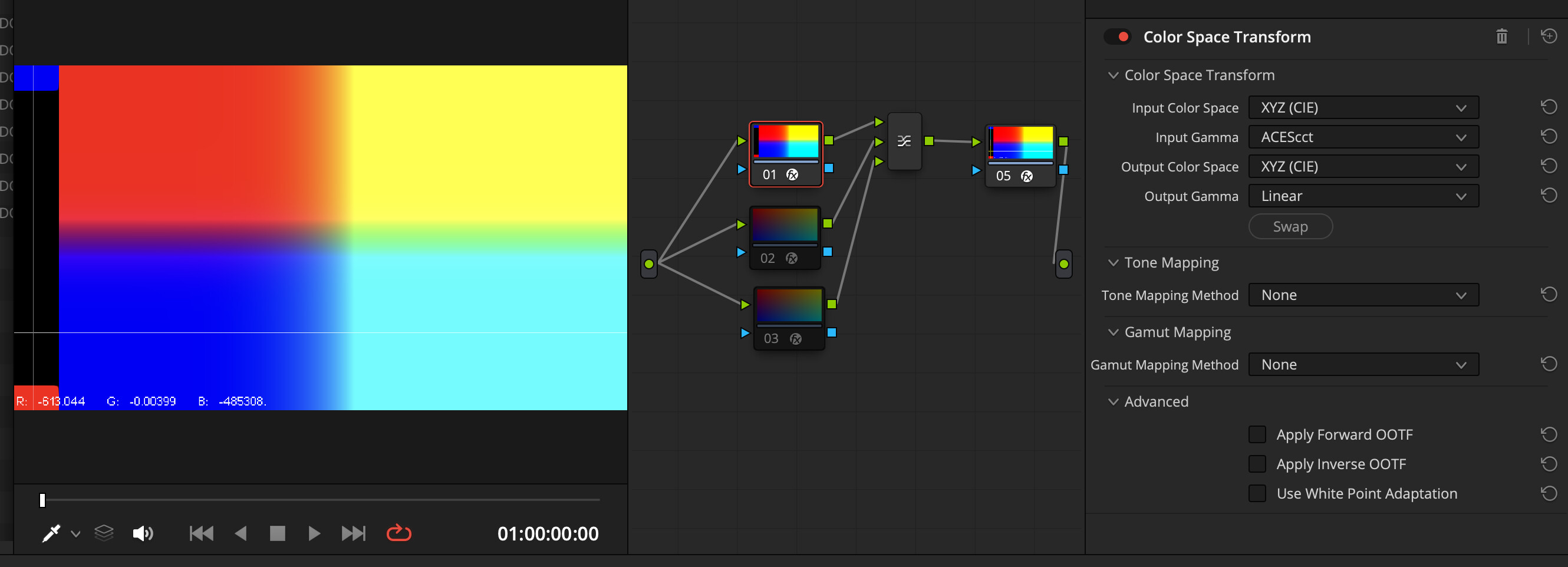
I was wondering if Resolve’s standard color space conversion is correct?
XYZ ACEScct to XYZ Linear
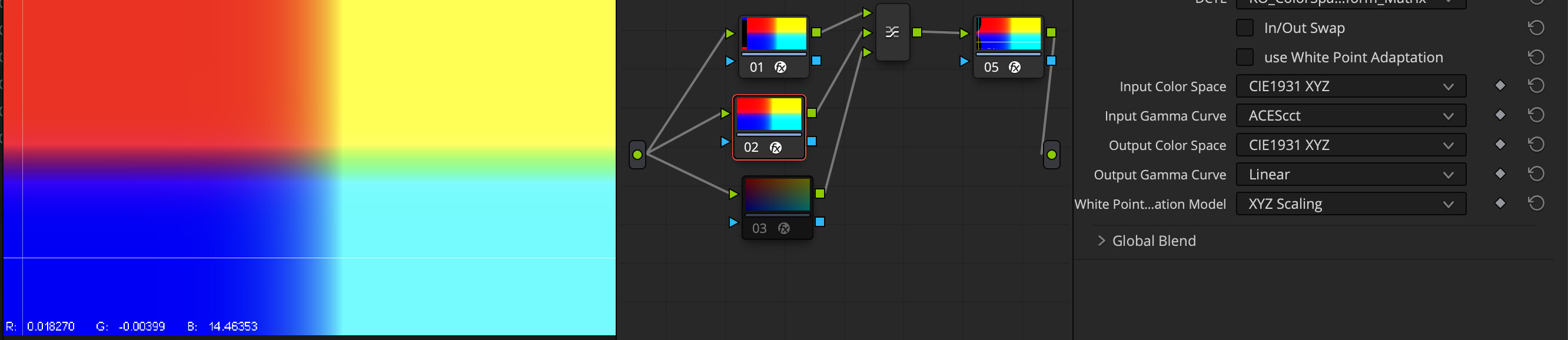
Only the left side of the screen turns black to indicate a huge negative value.
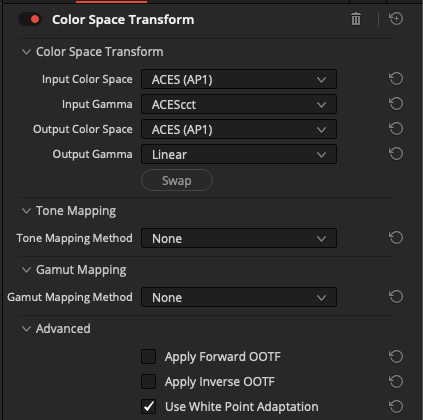
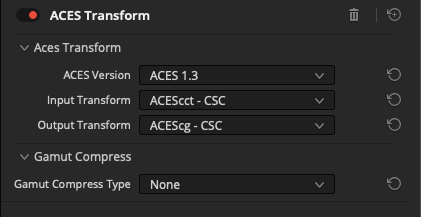
If your plan is to only convert log to linear the input space primaries should probably remain that of ACEScct on both ends, which would be AP1 rather than XYZ (CIE). It would essentially mean a conversion from ACEScct to ACEScg since they share the same primaries. This conversion can also be achieved with the ACESTransform node that would perhaps make a little more sense in ACES related pipelines.
As to the techinical explanation why this happens in XYZ I’m not entirely sure. It happens with any log curve with a toe and not ACEScc. BMD’s CST may have some preconceived notions on what to do with ‘gamma’ when the input primaries are set to non RGB, even if the ouptut primaries remain the same. Hope someone else can chime in.
If your plan is to only convert log to linear the input space primaries should probably remain that of ACEScct on both ends, which would be AP1 rather than XYZ (CIE). It would essentially mean a conversion from ACEScct to ACEScg since they share the same primaries. This conversion can also be achieved with the ACESTransform node that would perhaps make a little more sense in ACES related pipelines.
Yes, I agree, Usually, this would be the case for a conversion such as AP1 cct to some color gamut and gamma.
This time the question is about the simple cct(gamma) to Linear function.
In Resolve’s Color Space Transform, Gamut and Gamma can be selected separately.
In other words, I believe that cct(gamma) to Linear is theoretically implemented as a stand-alone function.
For study and understanding of Color Science, I am trying to create a clone of Color space transform in DCTL.
Currently, the output from this implementation is the screenshot below.
In theory you are correct. However this would appear not to be what happens here. The artefact you are seeing is specific to choosing XYZ (CIE) as the gamut. Something more than a 1D ACEScct to linear transform is happening. If you select e.g. ACES(AP1) as the input and output colour space the artefact does not occur.
So it is a problem on the Resolve side.
Thank you all very much for helping.
Incidentally,
Is it correct that Resolve’s “Apply Forward OOTF” is the rendering used when converting from Scene Referred to Display Referred?
It is like RRT in ACES?
I would like to know how it works, but it is Resolve’s own rendering and not publicly available function, right?
The rendering part would be the choice of tone mapping which is DaVinci by default. Their other options are older versions of their tone mapping. Unlike ACES, DaVinciDRT applies per-channel tone mapping directly after linearizing the input color space, so depending on where you came from the same source image can look wildly different. Generally people use DaVinci Wide Gamut / Intermediate as the working color space when using BMD’s color management.
The purpose of an OOTF is conceptually the same as the ACES RRT – a rendering transform to map scene colorimetry to display colorimetry.
However an OOTF normally consists of a simple gamma function (often applied to luminance only – see the BT.2100 HLG OOTF, for example) rather than the more complex sigmoid curve and colour processing of the RRT.
The Resolve manual does not specify what OOTF is used.
It’s also worth pointing out that “RRT” is no longer a term used in ACES 2.0, with the rendering applied using a colour appearance model (CAM).