In the CLF VWG meeting today we discussed the need for a test image that we will use for validating CLF processing accuracy. Here are some proposed requirements for the target:
Has a good range of colors, probably one or more log spaced grid/cube of some size. In my own targets, I’ve used three grids to cover normal, dark/negative, and super-bright areas separately to avoid having large numbers of extreme values that are not very helpful.
Covers a wide range of values. I will propose distributing them similar to half float values.
Includes +/- Infinity, +/- 0, and NaN.
Includes some shallow gradients to look for banding, both visually and on a waveform monitor.
Includes some solid patches large enough for easy locating/samping with an eye-dropper type tool.
No IP issues, may be contributed to open source / creative commons.
Not too big since it will make it easier to store/share lots of copies of it after processing through multiple CLFs.
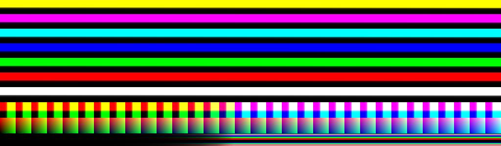
Some wide-range ramps in various pure colors (R,G,B,C,M,Y, neutral).
Would anyone like to add any other requirements? Does anyone have any targets that they could propose for this?
I am forming a sub-group to work on this deliverable, if anyone would like to join, please get in touch.
At this point this is a simply a discussion starter.
My focus has mainly been on the section down the bottom with single pixel high gradients. They are intended to outline the limits of a half float container, keeping in mind that we arent representing any specific colourspace, using ramps of both positive and negative values, allocated half float style (to the best of my understanding).
Something I notice when playing around with this, is that the current ephasis on covering ALL of the float range means the actual output may be a little misleading sometimes. For instance, when I compare my PureNuke ACES RRT/ODT vs a regular production OCIO version, the results look massivly different almost everywhere in the frame except the lower range ramps, and the middle of the -15 to +15 patch ramp.
And whilst this is true, the two are diverging heavily once values go over 16 or so, the reality is most production imagery will match between them.
You could argue that the whole point of this image is to show where CLFs could be doing damage outside the normal range, but I thought it was worth pointing out.
Here is some Python code I have for writing raw half floats into an EXR. It writes them into the leftmost 1024 pixels of the first 64 rows. By my reckoning the whole of the 32nd and 64th rows are “non-numbers”, so 2048 pixels, which means it isn’t possible to have a 1920x1080 image where all the non-numbers are in the top row, and can be easily cropped, as discussed in last night’s meeting.
import numpy as np
from colour import write_image

def uint16_to_half(y):
    y_int = np.copy(np.asarray(y)).astype(np.uint16)

    return np.frombuffer(y_int.tobytes(),
                         dtype=np.float16).reshape( y_int.shape)

img = np.zeros((1080, 1920, 3), dtype=np.uint16)

for y in range(64):
    for x in range(1024):
        h = (y<<10) + x
        img[y][x] = [h, h, h]

write_image (uint16_to_half(img), 'all_half_floats.exr', bit_depth='float16')
I’m using Colour, as I know it better, and it simplifies writing an ndarray to an EXR. But I’m sure it could be done easily using OpenImageIO directly. I’m also sure @Thomas_Mansencal could tell me how to more efficiently write the sequence of uint16s into the ndarray. But as it’s a one-off test image generator, iterating over pixels isn’t really a problem.
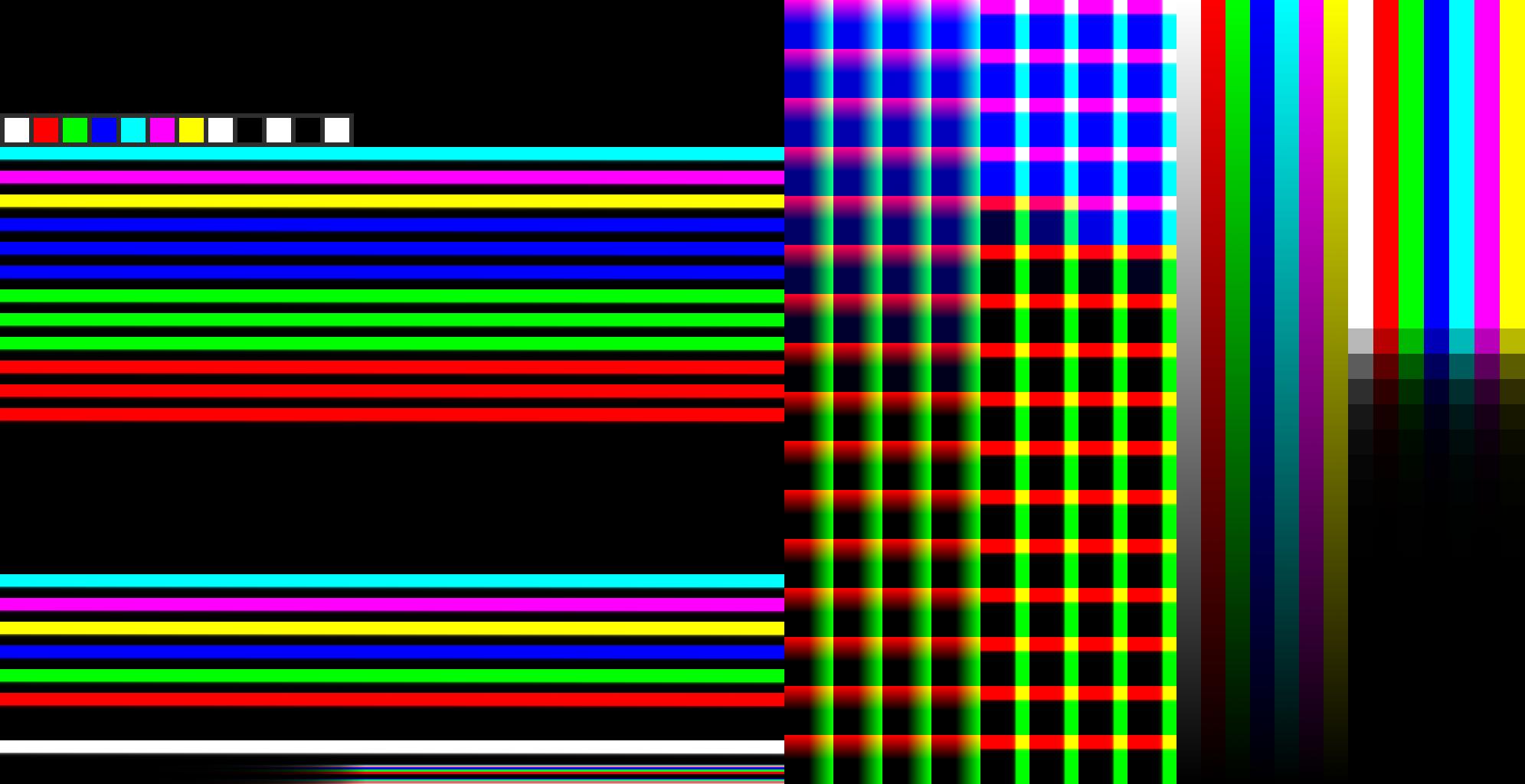
Biggest change is it now all sits inside 1024x1024
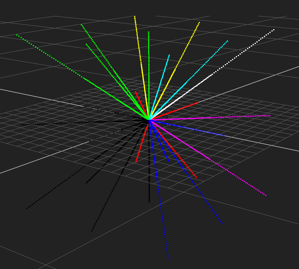
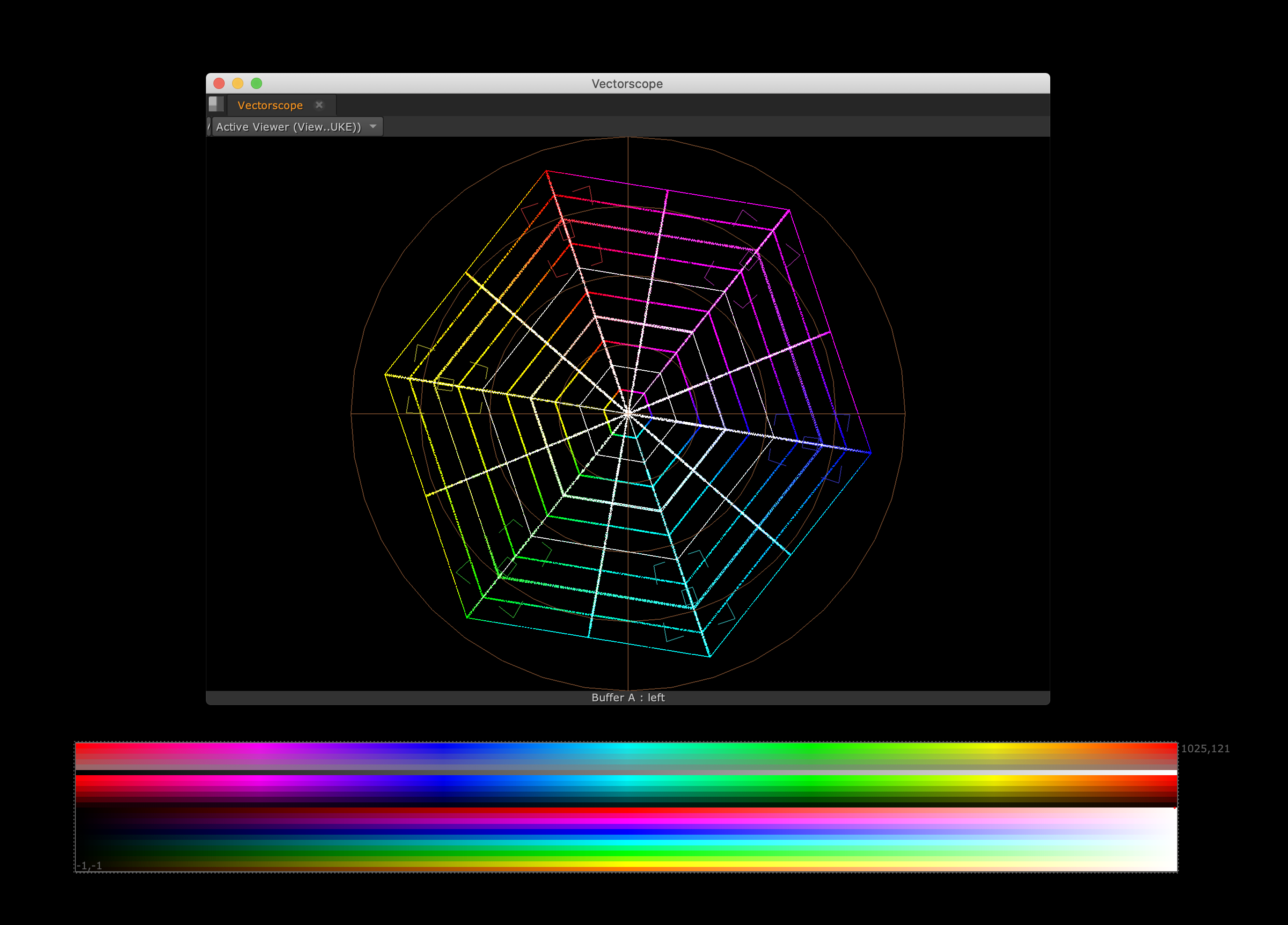
Nick’s spider web ramps have been added, but shrunk down to 1024 wide and 2 lines per stripe.
Inf/NaN values to first row to more easily exclude them, currently just the leftmost 2 pixel. Rest of the line is just black currently.
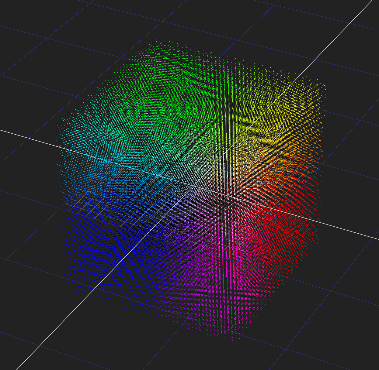
I’ve only got 1024 samples in the extents cube, rather than the space consuming “all float values” used in the last version. These ramps now outline the border of the cube too, which makes it easier to see where the borders are.
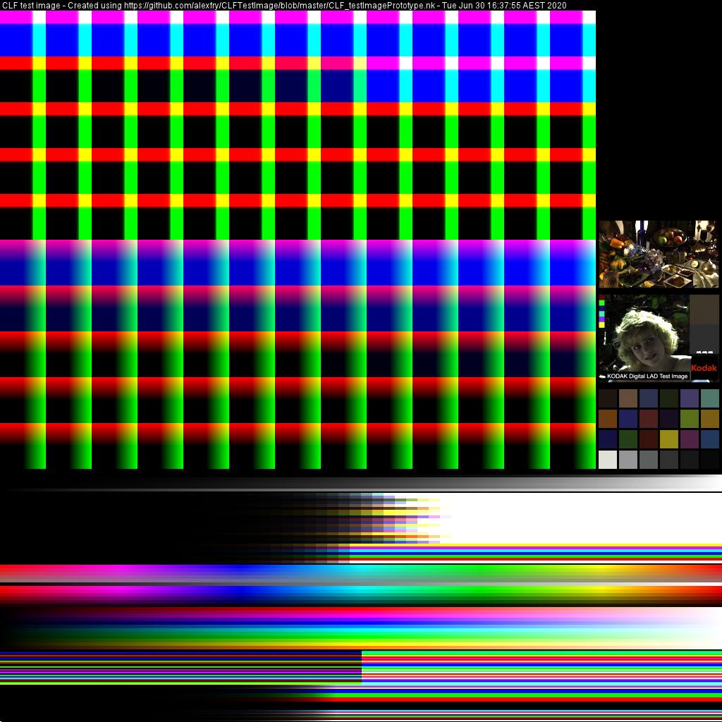
Added Macbeth patches in ACES2065-1 colorspace.
This has been down both with a traditional layout, as as parts of the 0.5 stop patch ramps above the pure colour 0.5 ramps.
All ramps are now horizontal so they read better on waveform monitors
Patch ramps centered around 2^-2.5 and in half stop increments
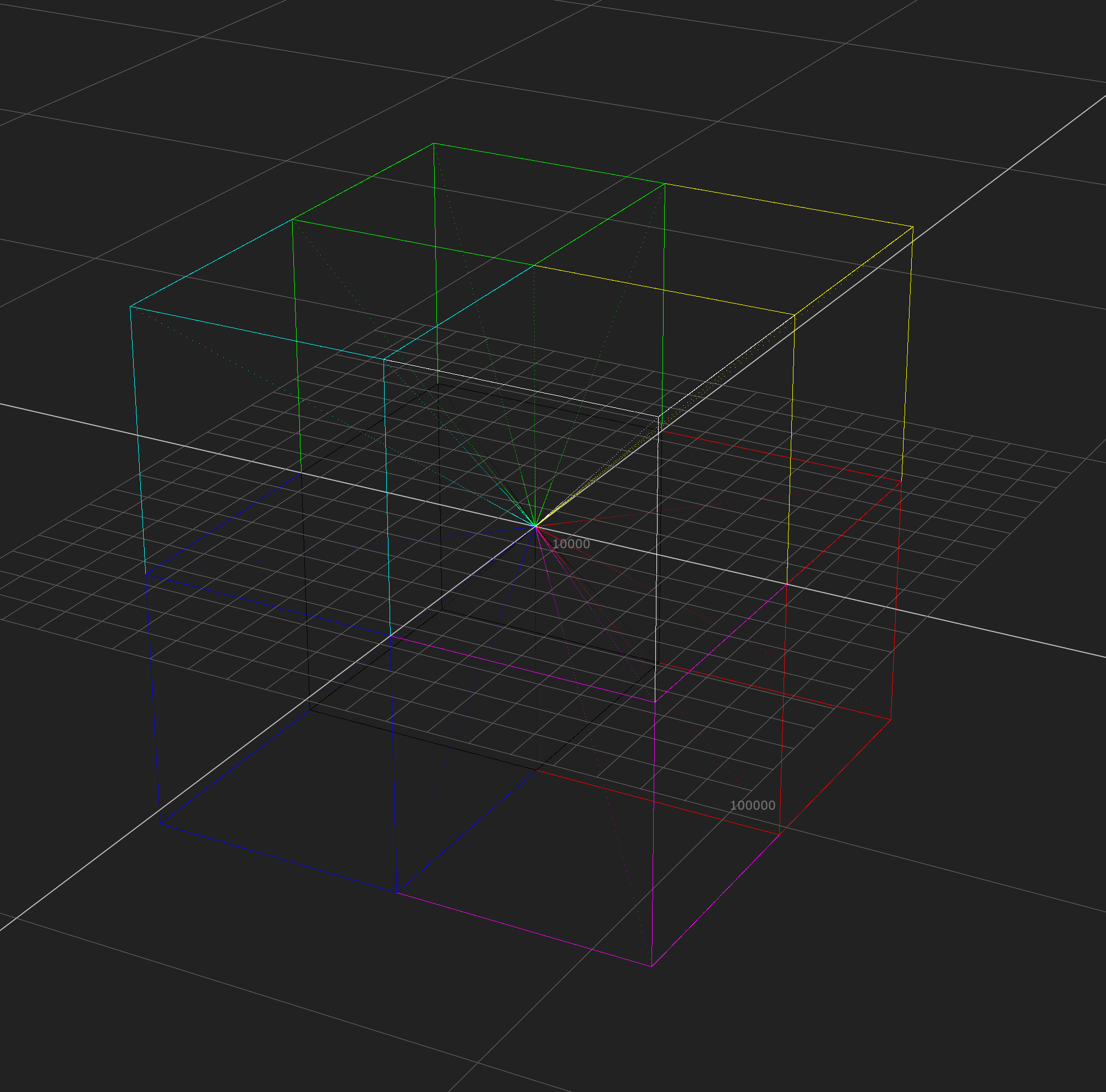
Cubes now use 65x65 so there is a centre point (0.0).
-1.0 -> 1.0 Linear Cube
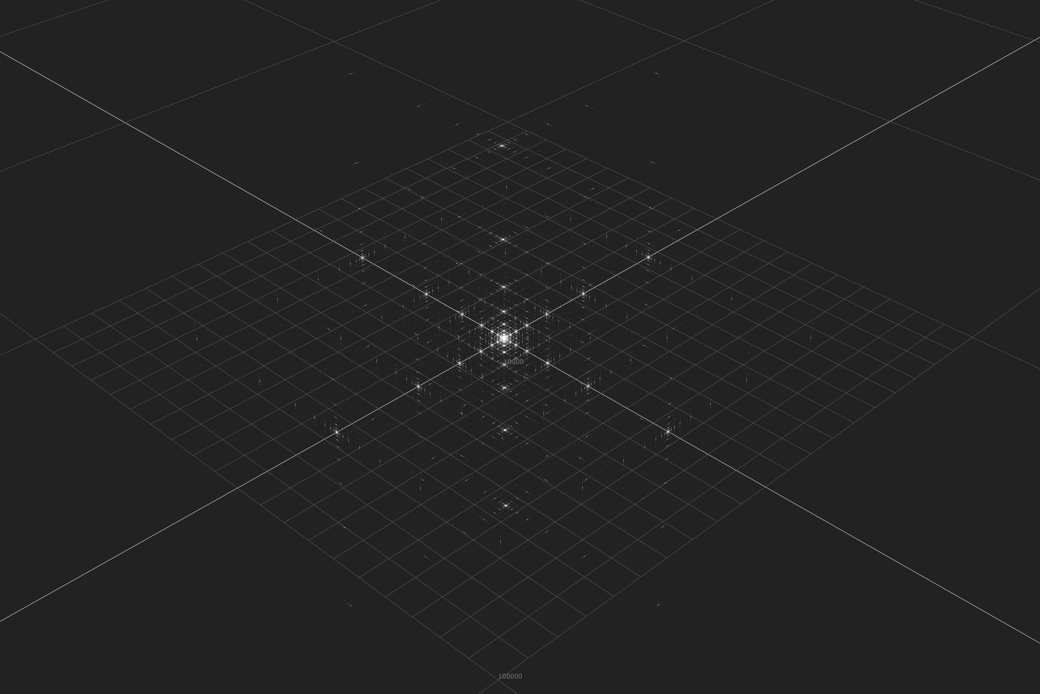
-65504 -> 65504 Log allocated Cube
I’ve popped in the two standard ACES test images (DLAD and StillLife). Bit controversial, but worth talking about.
And there are a set of greyscale 0-1.0 ramps. Threw these in at the last minute and haven’t really thought them through.
Linear
sRGB
Gamma 2.2
Gamma 2.4
Gamma 2.6
PQ
Also added some text at the top. Probably needs discussion.
I notice that when incorporating my “spider web” ramps, you’ve kept the grey ramp in the middle. That’s just a linear 0-1 ramp, which already exists elsewhere in your pattern. I think I stuck it in mine because there was some spare space, and it was another thing to make the pattern more universally useful. But it seems redundant here.
Regarding the Macbeth Chart, you are using the “After November 2014” patches from @Thomas_Mansencal’s colour-science for Nuke. While close, these don’t quite match the ACES reference values on page 11 of S-2016-001. I’m not sure what the derivation of those values is. Perhaps @Alexander_Forsythe or @sdyer can comment.
Pasting into this thread my notes on LUT box CLF testing:
Test CLFs for hardware LUT boxes
I’ve not managed to install a build of OCIO 2.0, so haven’t been able to actually test anything for real. I have started hacking some of the new CLF 3.0 operators into my simple Python implementation of CLF, but its not complete.
For testing of hardware boxes, what is our aim? Do we e.g. provide a 10-bit DPX test image and assume the implementer has the facility to play that out as exact RGB SDI code values, and capture the output of the LUT box as a 10-bit DPX containing the exact resulting SDI code values? If so, we need only provide before and after images.
Alternatively, do we assume that a hardware device will have to bake the CLF into a single 3D LUT (optimising for devices which can implement e.g. 1D + 3D + 1D introduces too many permutations). In that case, all we need to provide is a reference 3D LUT which is the result of “flattening” the CLF in OCIO. They could potentially use OCIO conversion in their own system, in which case they should get a perfect match, or we specify that their parser/converter should produce table values in the 3D LUT within a given delta of the OCIO values.
Beyond specifying that the hardware should use tetrahedral interpolation, do we specify a test for checking that is working as expected? Or do we trust their implementation of that?
For hardware boxes, any LUT which expects or produces linear data is unsuitable. Essentially only LUTs which expect and produce log or “video” data are suitable. Some possible examples modelled on real world scenarios: