ACES 2.0 CAM DRT Development

Would that value need to change for each viewing colour space - like P3 or Rec2020?

We certainly don’t want something where a value has to be manually chosen for each target. If a different value is needed, it should be derivable for any arbitrary target by a clearly documented method, even if it cannot be set procedurally within the rendering code.

I don’t actually think that 0.95 would necessarily be good threshold. Might be ok for red but might not be for blue. The threshold defines how far in gamut the out of gamut values are pulled in (so that the compression stops at the 1.0 boundary when the limit is reached). 0.95 doesn’t give much room. Maybe with the reach gamut mapper it should also change the threshold based on the reach limit?

Good day! I am following this thread and others with respect to gamut mapping BT.2020 to smaller gamuts using MadVR renderer for dynamic tone mapping HDR to much lower nit displays such as projectors.

At the moment we are working on Gamut Rolloff over on AVS Forum and your thread has helped us with some ideas and direction in our journey thus far.

I wanted to ask, does anyone here happen to have the ACES test shots in HDR format that we could then use to tone map and gamut map so we would have a point of comparison? Unfortunately I cannot use Nuke and my Resolve skills are limited in this regard to be able to export them on my own, they seem to be exceptional test files particularly the high brightness spheres I keep seeing.

I was able to download the ACES OT Sample frames exr’s but I wondered if anyone would be able to export an HDR Mp4 or the like for 1,000 nits BT2020 at all? Or If there already exists an HDR export would you mind pointing me in the direction of it to download?

Thanks very much sirs and I apologise if this post is considered off topic.

I should mention, 45 seen in last week’s meeting, is now in the LUT repo.

This is also the first set that includes Resolve 18.6 buffer tagging for the DCTL versions, which will allow for proper HDR display on EDR monitors under MacOS, and adds HDR metadata to video out feeds.

2 Likes

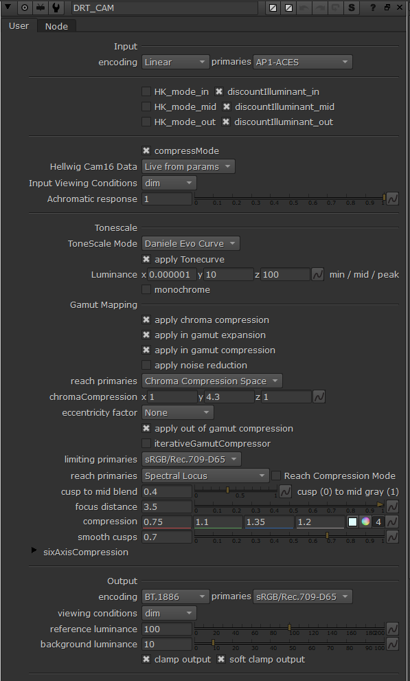
I’ve sent a pull request for CAM DRT v046 for @alexfry. It brings the following changes:

  • Improves HDR/SDR match
  • Adds the chroma compression space as optional reach space for gamut mapper
  • Adds AP0, AP1 and Rec.2020 as optional reach spaces for chroma compression

Chroma Compression Space

I haven’t previously plotted the chroma compression space, so here are the chroma compression primaries used in v046:

CIE x CIE y
Red 0.7347 0.2653
Green 0.12 0.88
Blue 0.08 -0.04
White 0.32168 0.33767

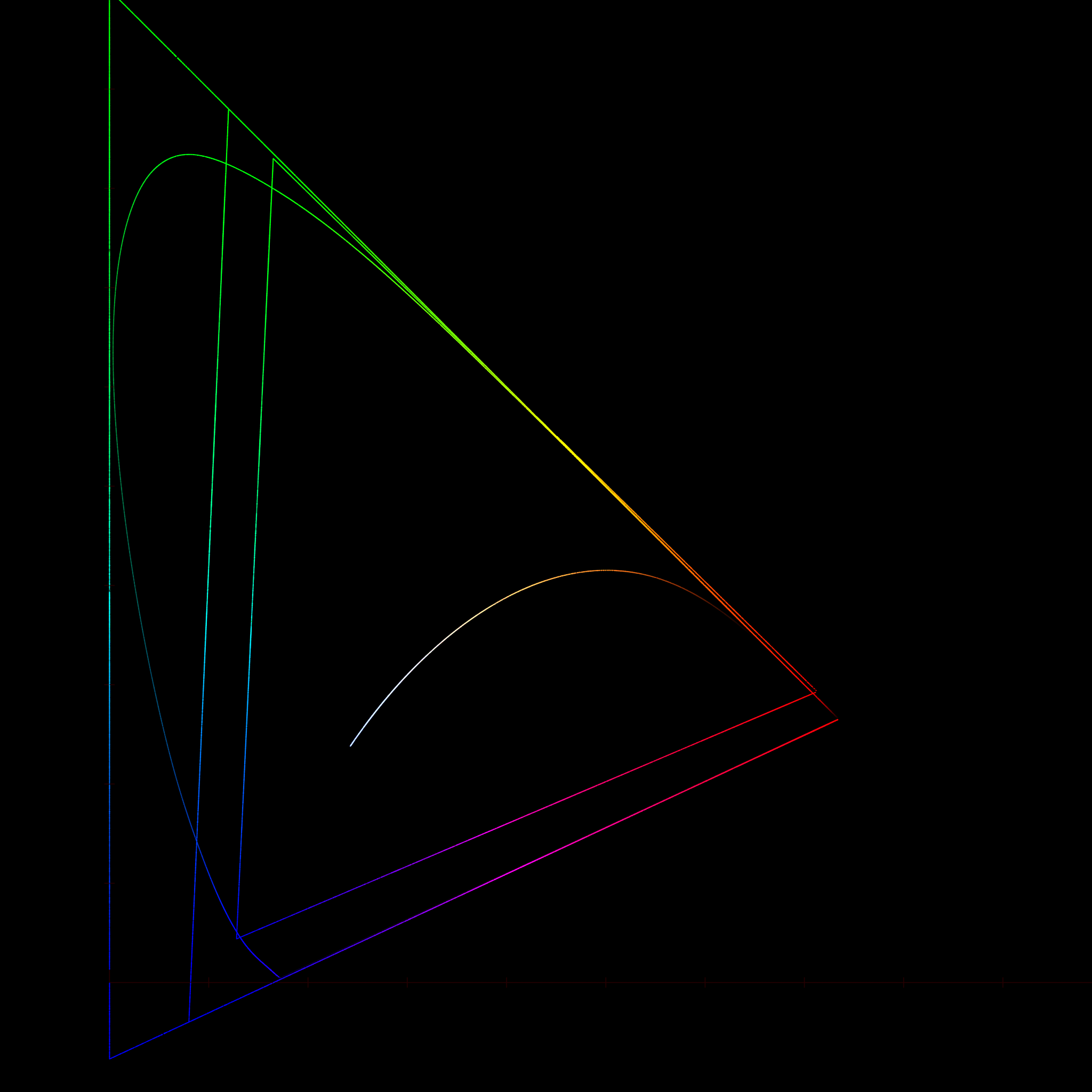
The following diagram shows AP0, the chroma compression space, and AP1, in that order from widest to narrowest:

In this version these primaries are also available to be used in the gamut mapper when reach mode is enabled:
v046_mapper_reach_primaries

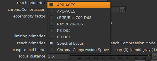
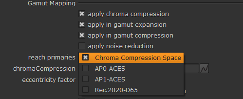
I also added AP0, AP1 and Rec.2020 as alternative chroma compression primaries:
v046_cc_reach_primaries

HDR/SDR Match

This version should have improved appearance match between Rec.709 and Rec.2100. I also tested Rec.2100 against ACES1 Rec.709 since it was found to match well with Rec.2100. I found that it matched well also. To my eye it was following reasons why it matched well:

  1. Rec.2100 was too colorful. It was matching the saturation level of ACES1 more than CAM DRT v044/45. This has now been adjusted in v046.
  2. Higher contrast of ACES1 makes certain images feel brighter and closer to Rec.2100. CAM DRT Rec.709 can feel darker. This applies only for the top end. Bottom end is darker in ACES1 and doesn’t match at all.
  3. Some colors (like green) seems to benefit from clipping and skewing towards the primary in ACES1, making it feel closer to Rec.2100 green (the “Fairy Bottle” effect). I found many more examples where the skew caused it to not match at all.
3 Likes

Looking at v048 @ 1000nit P3D65 limited, and I’m seeing some artifacting compared to previous versions. Look in the top colored shelf in the ARRI “Bar” image - I am seeing splotchy color in the magenta and purple areas, whereas in previous version this was not visible.

Are others seeing the same? Any ideas on what change may have introduced this?

EDIT: “Blue bar” also seems quite dramatically different. Like the blue is clipping out at full blue again. I like the blueness but hate the clumpiness. The differences should be particularly visible when toggling between the Rec2020 (709 sim), (P365 540 nit limited), and (P3D65 1000 nit limited).

I see the same in blue bar, and it is, I believe, because the reach mode is now using AP1. As has been discussed the blue primary is “too close” in AP1 so camera imagery with highly saturated blues will now clip. Previously the reach mode was using the “Chroma Compression Space” in chroma compression, and something as wide or wider in gamut mapper.

I’m still for using wider reach space to make the forward direction better. I woud sacrifice the inverse direction for forward direction, not the other way around. But that’s me…

One reason for using wider reach space is that we might then be able to get rid of RGC, which simplifies the system. Using AP1 will mean that RGC probably is still needed.

Here’s what the reach space could look like (could be called AP2 if people want new official space). This version covers AP1 too. The suggestion would be to use this for both chroma compression and gamut mapper.

It’s the eternal circular problem, isn’t it. If you make the rendering able to pull out of gamut colours like blue bar to the target gamut boundary, then you will need to push colours to that same out of gamut place in grading if you need to hit that boundary. But standard grading tools cannot push values out of gamut in a controlled way.

So I personally think we need to limit the rendering to only handling AP1, which people can grade right to the edges of, and accept that the RGC is still needed for extreme images.

I suppose rather than AP1, we could have a reach gamut which goes to the bounds of 0-1 in ACEScct, because that is the domain people actually have for grading. Or if ACESlog goes more negative…

1 Like

Can we then just clamp the input to AP1? We could remove the compress mode then as well. The model should handle AP1 input without issues. And we could perhaps go back to stock primaries also.

Here’s the comparison. Clamp to AP1, no compress mode, Thomas’s primaries vs Stock primaries:


AP1 still includes negative XYZ values, so even clipped to AP1 we would need compress mode or an alternate matrix (the Thomas matrix?) to handle that.

I just tested the stock matrix, and without compress mode it cannot round trip an AP1 unit cube to JMh and back.

Edit: Tested again with the Thomas matrix, and that still won’t round trip AP1 to JMh without compress mode.

Glad to see discussions in this particular area, I would like to think this is closer to tuning (maybe not quite fine tuning) rather than fixing something that is broken.

I just want to clarify (or correct) my comments made in the last meeting regarding the diver image,

The red channel is clipped in both 709 and P3 renders. I may have suggested they were not.

The divers face is not clipped in the red channel of 709limited P3 which of course should make sense since a transform from 709 to P3 would allow information from unclipped channels to place information into red channel inside larger container. So this is not the strange behaviour that was noted in Arribar image.

The Arri Bar (green area) had the less intuitive situation where the rec709 showed less clipping than P3.

I would still suggest that it would be ideal to see less clipping on the Divers face, as it also limits the quality/range of the inverted image as well.

I guess I am a little hung up on the idea that if the 709 limited P3 can eliminate clipping (at the cost of chromaticity) there might be “false” gamut (or gamut target) in between 709 and P3 that could at least lower or limit the amount of clipping, with some increased chromaticity.

I have been doing some investigation into possible issues we have seen, and have had some private discussions about them with @priikone. I thought I should post my findings in this public thread.

For the purpose of testing, I have taken the XYZ_to_Hellwig2022_JMh and Hellwig2022_JMh_to_XYZ Blink functions and copied them to a separate library file, with minimal modifications to enable them to operate in a stand-alone way. Then I have made a Nuke script which uses those functions in simple RGB → JMh and JMh → RGB nodes.

One change I did make is that my Blink outputs the h value in radians, to eliminate the multiple conversions to degrees and back, which happen in the DRT. Although in fact I saw no significant effect from this change.

The first issue I investigated was the fact that we have seen a shift when round-tripping an sRGB unit cube to JMh and back.

I do not see this shift when using my simple round-trip nodes. Although I fact, when setting the DRT to be sRGB in and out, with all tone-scale and chroma and gamut compression off, I do not see it either, unless I have a reference white mismatch. @priikone discovered that the DRT appears to effectively apply a chromatic adaptation to the white point of the limiting primaries, even if gamut compression is inactive. Initially I thought this was a bug, but in fact because the limiting and final encoding are separated, I believe it is appropriately acting in a “sim” mode when the limiting and encoding white points do not match. In fact, I think it might be useful to separate the primaries and white point of the limiting gamut into two separate parameters, as doing things like limiting to Rec.709 primaries with ACES white, and then encoding the output as Rec.709 with D65 white would (with the addition of a little scaling to prevent clipping, the same as the current ODTs) produce a “D60 sim” Rec.709 output.

So I have not found evidence of a shift when round-tripping a display-referred unit cube in the way it would be used in production – going through the inverse DRT to produce scene values which recreate the original display values after the forward DRT. When using the original (non-reach-mode) gamut compression in v49 I get a near perfect round-trip, with negligible changes attributable to the limitations of float precision. I do see distortion when using reach compression mode, but as I discussed in the last meeting, I believe that imperfect invertibility of reach compression is to be expected the way it works currently.

I am also still not convinced that reach compression is an appropriate approach. The thinking behind it is that values on the reach gamut boundary (e.g. AP1) will be compressed exactly to the target gamut boundary, and likewise values on the target boundary will invert exactly to the reach boundary. But that would only be the case if the gamut compression were being applied directly to unmodified scene values. That is not the case. Tone and chroma compression will have already modified the values by the time gamut compression is applied, so values which started on the AP1 boundary may well be well within it, particularly for bright values that fall into the “path to white zone” of the chroma compression. Thus reach gamut compression will compress these values far more aggressively than is actually necessary for the intended aim. Similarly inverse gamut compression will map values on the target gamut boundary to the AP1 boundary, but they will not necessarily be left there, and may well be moved out further by inverse chroma compression, putting them outside AP1.

So while it of course important to verify that everything is wired up as intended in the DRT, with the appropriate reference white values used at each stage, I do not believe that the “tilt” in the above chromaticity plot is evidence of a problem with the DRT. I believe it is only a problem when the DRT is not used as intended, but rather forced into a non-standard mode for testing. I think this makes a strong case for a breakout version made of entirely stand-alone nodes, each dedicated to a specific process with only appropriate parameters exposed, rather than using diagnostic modes hacked into the full DRT, where it is often not clear which of the many parameters of the full DRT affect the particular sub-process.

The second issue that I investigated was the distortions of high luminance values in the dominant wavelength test image.

Again I could only match the issue seen previously by using the DRT in ACEScg in and out mode, with “everything off”. My stand-alone JMh conversion nodes round-trip to within expected precision. I expected the artefacts when using the DRT to be the same whether the input was AP1 or AP0, as the resulting XYZ values, which are what is converted to JMh, should be the same. This is not the case. This lead me to the conclusion that the artefacts produced using the DRT are a result of the clamp to HALF_MAXIMUM applied to input RGB values. The dominant wavelength image contains RGB values significantly above 65504.0, although the exact values differ for AP0 and AP1.

I therefore do not believe that the artefacts shown in the chromaticity plot above are of concern in the rendering of real images. If values as high as those in the dominant wavelength image need to be processed without clipping, then the clamp value in the DRT can be raised above HALF_MAXIMUM. That limit is in some ways arbitrary, and based on the assumption that RGB values fed to the DRT will come unmodified from a half-float ACES EXR. This will in fact rarely be the case, since grading and compositing processes will inevitably alter the source values.

One final issue which @priikone and I discussed was the fact that equal input RGB values do not result in zero M values. This issue I could replicate with my stand-alone node. An achromatic ACES ramp produces small (7th decimal place) non-zero M values, and h values which oscillate between 0 and 180 (or 0 and \pi in my radian based variation). No in between h values occur; only those two. My investigations suggest that this issue is down to the fact that the Hellwig model calculates non-linear L’M’S’ values for the source pixel and for reference white, and then divides one by the other. This should produce normalised L’=M’=S’ for achromatic source pixels. However processing precision limitations mean this is not precisely true, and therefore the resulting a and b values, and the M value calculated from those, are not precisely zero, and h also varies. So the question is whether this is a problem. @daniele has commented previously on the potential for problems caused by wildly varying hue values in near-neutral pixels. However because it is only the gamut compression which is modulated by hue, and this should not affect near-neutral values in any way, these values should be converted to near-neutral output RGB unaffected by the fact that they had varying hue in the JMh working space. We should certainly continue to investigate, but I have not found any evidence of noise introduced in near-neutral values due to this effect.

3 Likes

I have just operned a pull request for a v050 which separates the primaries and white point of the limiting gamut into two separate drop-downs, as discussed in the last meeting. It also includes a fit white check-box, which applies a linear scaling to the output to ensure that a ‘simulated’ peak white is not clipped in the encoding space.

All the function definitions, and the init() block are broken out into separate library files, to make ‘exploded’ versions of the DRT easier to build. Unfortunately, because Blink does not allow script-relative include paths, to run the Blink on your own system it will be necessary to edit the two include lines to your own local paths.

Edit: it’s now three include lines, since I added back the diagnostic modes as an include.

2 Likes

@nick your PR has been merged!

After a bunch of wheel spinning at errors, trying to workout why 49 and 50 were both blowing up in my face, I finally realised you guys has switched to Nuke 15.0 (Derp…)

I’ve updated the LUT Repo with new bakes:

This contains the new 50, and revised 48.
The new OCIO Config template uses the 709 LUT for the 709 Limited P3D65, which massivly improves the inversion.

Currently this is only in the OCIO version. I’ll need to look at the Resolve DCTLs seperately.

Ah yes. Sorry if that messed you up. My laptop and desktop here are both Apple Silicon, so native support in Nuke 15 makes a big difference to me. Is something particular required when saving scripts from v15 to ensure backward compatibility?

@alexfry @Thomas_Mansencal (viz) @here

Sorry for the probably excessive ping, but I want to notify interested parties that Dr. Luke Hellwig has just defended his dissertation with additional work on CAM. It’a well worth testing.

lhCAM23 is not tested or modeled on HDR luminance ranges, so there may be strange behaviors there. In his defense he mentioned that they are actively pursuing future work on this, as well as on understanding local adaptation and image context (iCAM extensions possible in the future)

6 Likes

Also just saw our man @luke.hellwig got some prime time recognition in this recent Linus Tech Tips video!

2 Likes

For those playing along at home, I’ve just uploaded a v052 with should have the latest changes from @priikone @KevinJW @nick and myself.

Blink for Nuke:

Along with LUT bakes:

4 Likes

This is a recap of the gamut mapper issue in CAM DRT v052 talked about in the past couple meetings.

The basic issue is that with the current gamut mapping implementation it is not possible to change the projection angle to a steeper one, in order to better preserve highly saturated colors in the highlights in SDR, without introducing issues with gradients.

Important to point out up front that this issue is not related to the reach mapper or how far out the gamut mapper reaches in compression. The same issue happens also in non-reach mode.

Following images are ramps of Rec.709, P3, Rec.2020, AP1, AP0 and AWG inputs, in CAM DRT v052 with focus distance value set to 1.0 for a steeper projection. This is a way to clearly demonstrate the issue:

What we’re seeing here is that not all of the mapped hues have proper path-to-white. All colors are mapped within Rec.709 gamut, but only the Rec.709 input seems to have path-to-white for all the hues. All other examples show that some or most of the hues instead clip to white.

This happens because the quadratic used in the computations doesn’t have the ability to smoothly change the projection from a steeper angle to a more horizontal angle as it approaches display white (and black), as shown in the example slope plot below.

No path-to-white:
intersectJ_clip
Smoother path-to-white:
intersectJ_path_to_white

Here is an example rendering of the above ramp image with a mapper that always has a path-to-white for any input value. This is the experimental version of the AP1 reach mapper:

Here’s one example of the implications of not having path-to-white (focus distance 1.0):


Smooth path-to-white:

As far as I can see, there’s few things that can be done about this:

  1. Do nothing, and set the focus distance to a high enough value (near horizontal projection) so that the slope hits the display white with shallow enough angle so that visually everything looks to have smooth path-to-white. This is the current approach. The downside is that highly saturated colors will lose saturation very quickly in SDR. The current value in v052 was picked to have visually smooth path-to-white in AP1, but AP0 and beyond shows clipping.

  2. Go back to the old mapper we have which has smooth path-to-white for any input value. This mapper doesn’t use the quadratic approach. A reach version of that mapper can be done the same way as the current one. The downside is that the inverse will become an approximation. This mapper would have no limitations on how steep the projection is, it would always have smooth path-to-white, regardless of the input value.

  3. Perhaps a separate path-to-white step after the gamut mapper could be added, but it sounds hacky.

4 Likes