This is a recap of the gamut mapper issue in CAM DRT v052 talked about in the past couple meetings.
The basic issue is that with the current gamut mapping implementation it is not possible to change the projection angle to a steeper one, in order to better preserve highly saturated colors in the highlights in SDR, without introducing issues with gradients.
Important to point out up front that this issue is not related to the reach mapper or how far out the gamut mapper reaches in compression. The same issue happens also in non-reach mode.
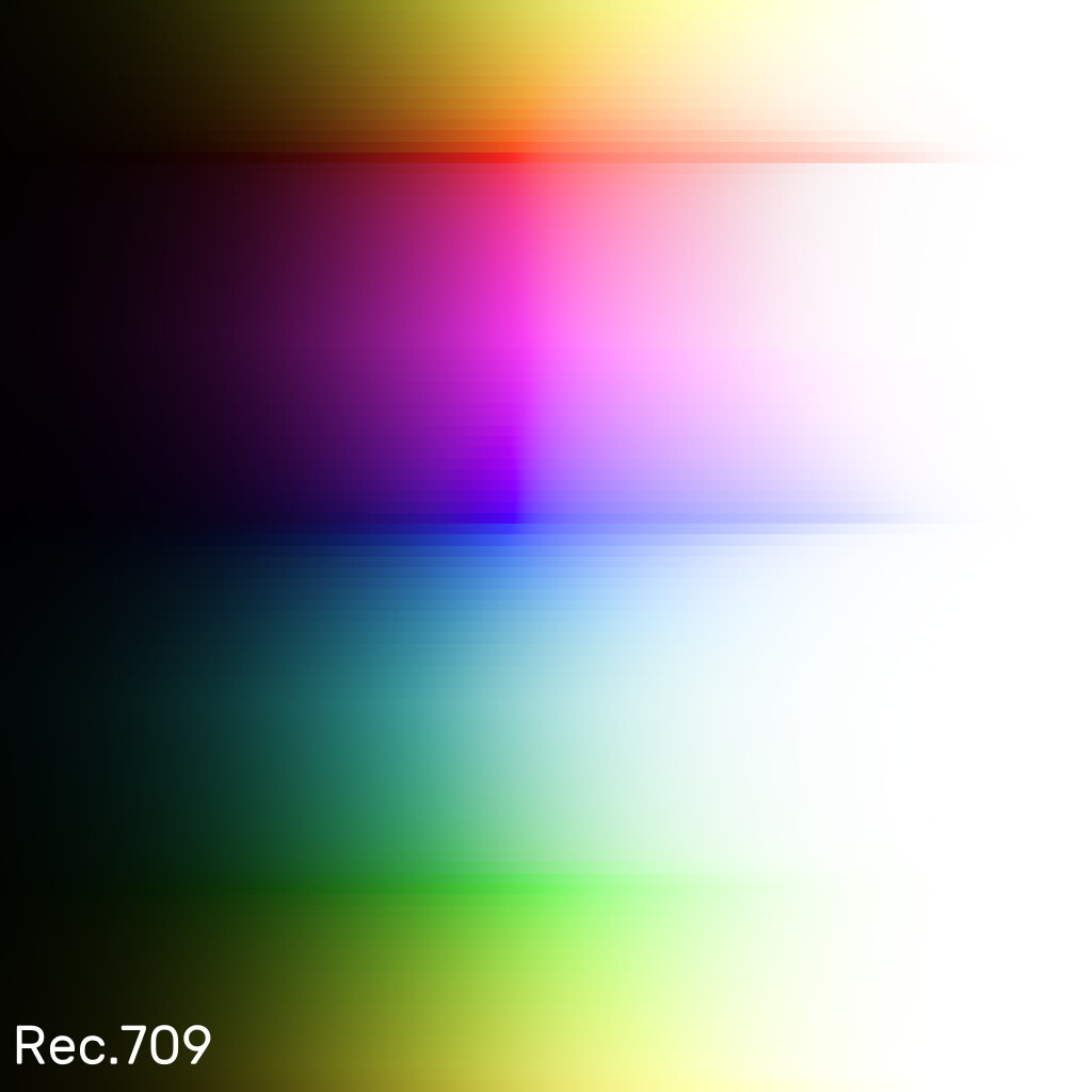
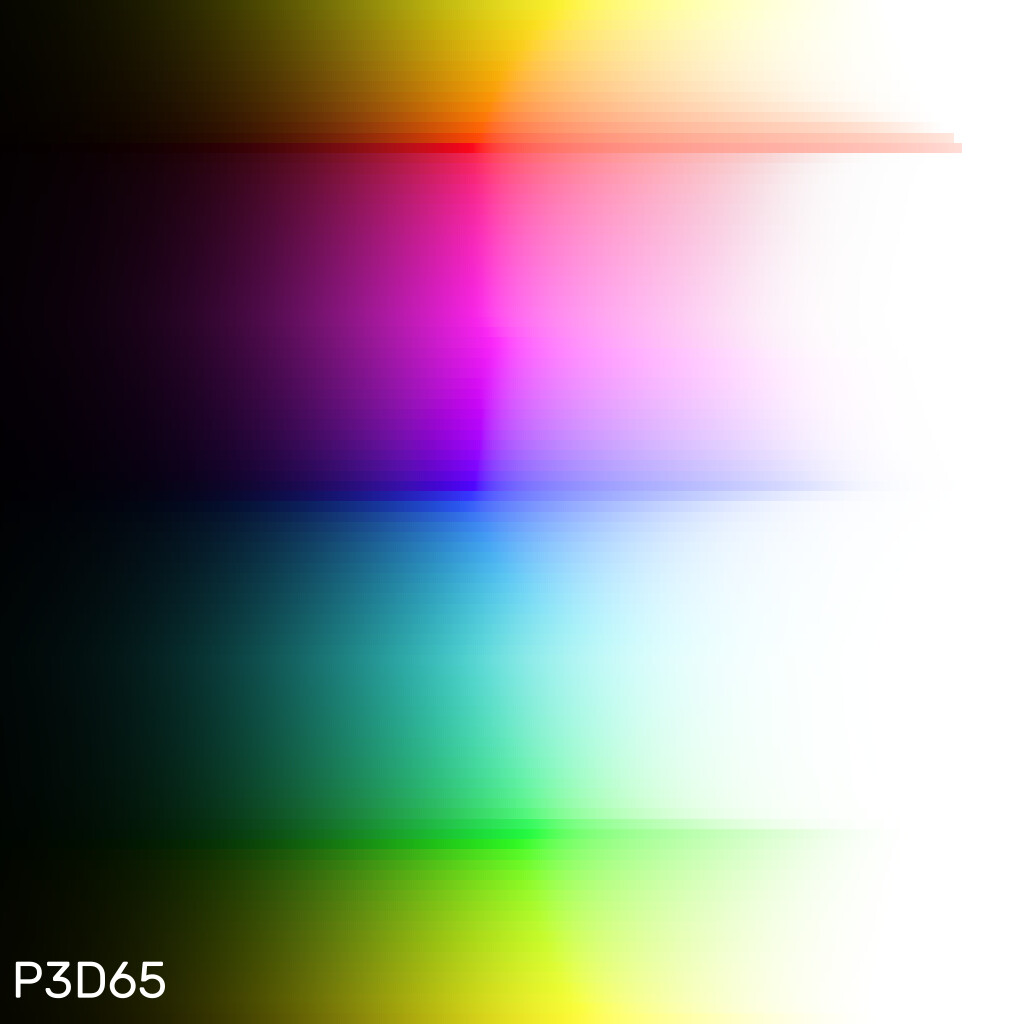
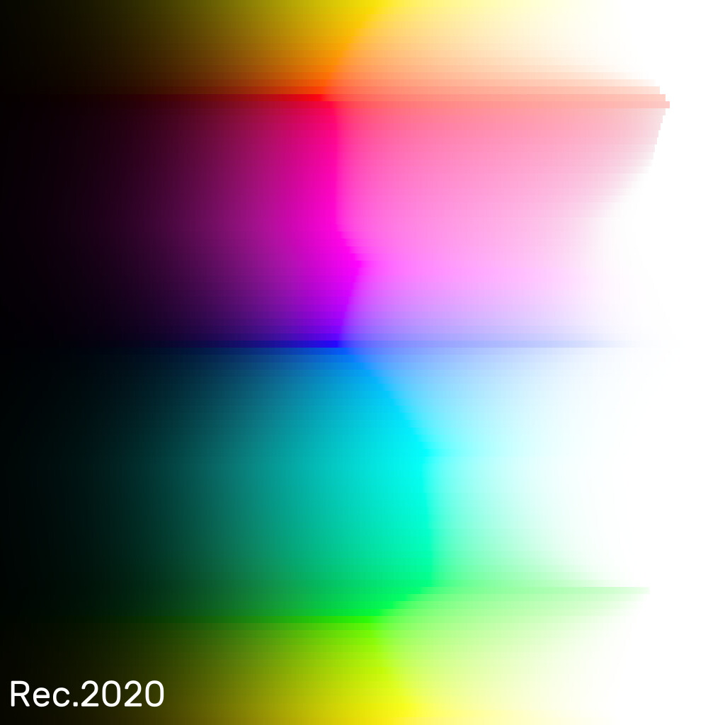
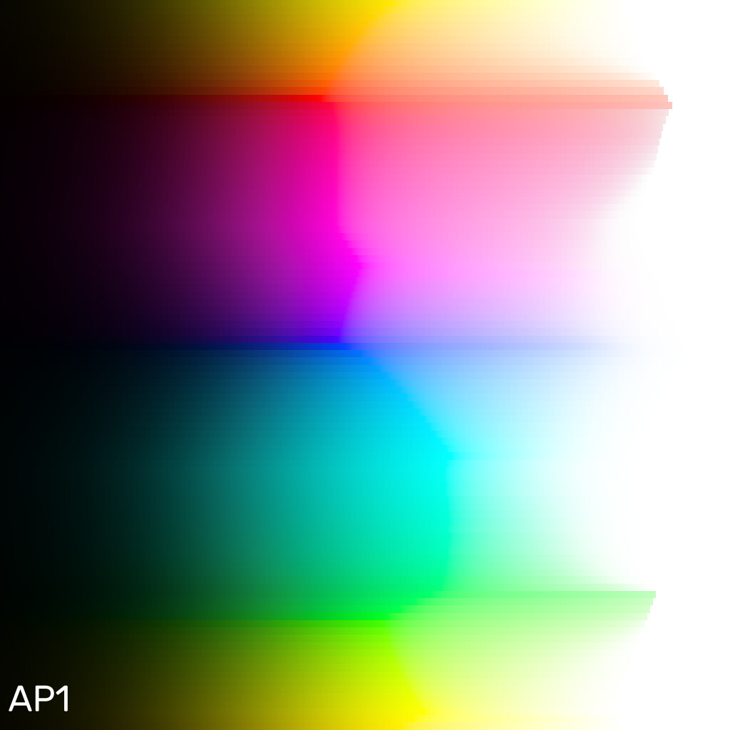
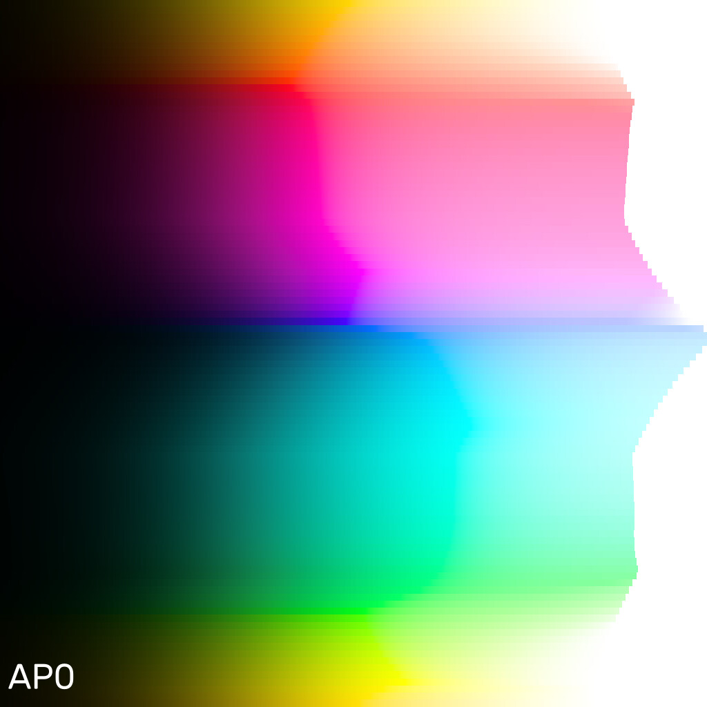
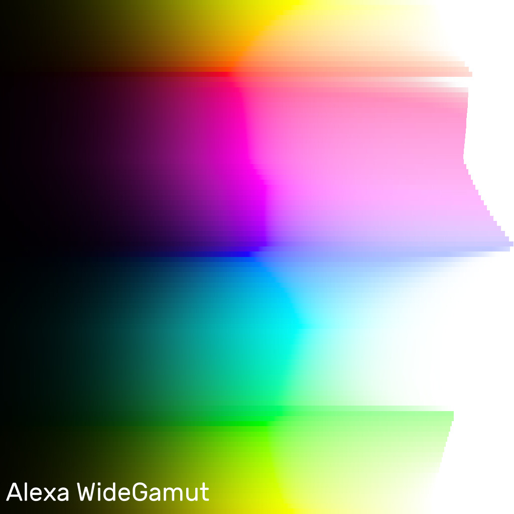
Following images are ramps of Rec.709, P3, Rec.2020, AP1, AP0 and AWG inputs, in CAM DRT v052 with focus distance value set to 1.0 for a steeper projection. This is a way to clearly demonstrate the issue:
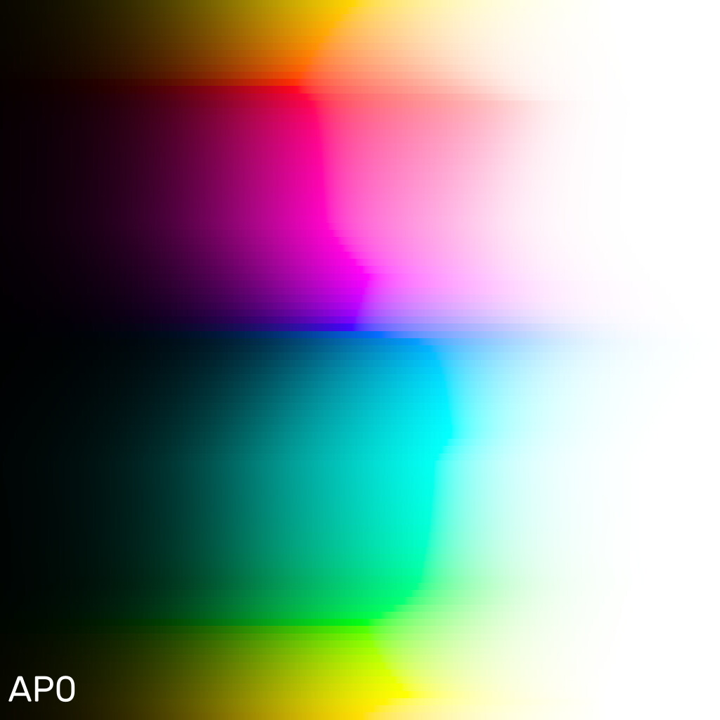
What we’re seeing here is that not all of the mapped hues have proper path-to-white. All colors are mapped within Rec.709 gamut, but only the Rec.709 input seems to have path-to-white for all the hues. All other examples show that some or most of the hues instead clip to white.
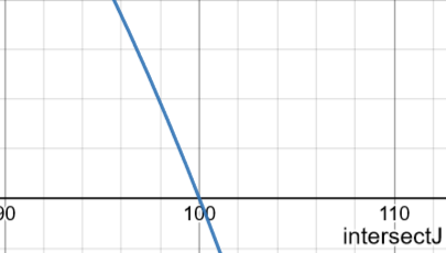
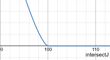
This happens because the quadratic used in the computations doesn’t have the ability to smoothly change the projection from a steeper angle to a more horizontal angle as it approaches display white (and black), as shown in the example slope plot below.
No path-to-white:
Smoother path-to-white:
Here is an example rendering of the above ramp image with a mapper that always has a path-to-white for any input value. This is the experimental version of the AP1 reach mapper:
As far as I can see, there’s few things that can be done about this:
Do nothing, and set the focus distance to a high enough value (near horizontal projection) so that the slope hits the display white with shallow enough angle so that visually everything looks to have smooth path-to-white. This is the current approach. The downside is that highly saturated colors will lose saturation very quickly in SDR. The current value in v052 was picked to have visually smooth path-to-white in AP1, but AP0 and beyond shows clipping.
Go back to the old mapper we have which has smooth path-to-white for any input value. This mapper doesn’t use the quadratic approach. A reach version of that mapper can be done the same way as the current one. The downside is that the inverse will become an approximation. This mapper would have no limitations on how steep the projection is, it would always have smooth path-to-white, regardless of the input value.
Perhaps a separate path-to-white step after the gamut mapper could be added, but it sounds hacky.
This looks rather like it might shred to bits on pictures formed from tristimulus colourimetry that have transparent with reflected sheens or sharp reflections in it.
I have a very strong inclination that testing tristimulus data with an attempt to express this sort of spatiotemporal articulation will reveal the rate of change along the purity dimension as being too slow. The tests, I suspect, will reveal a cognition of the “things behind” the reflective surface as “punching through”.
One thing I tried experimenting with when I saw the shape of your desmos plots was using a cosine raised to a power to create a “hat” weighting function for the current mapper, i.e. a function that is mostly 1 but falls off rapidly but smoothly near 0 and 1, unfortunately I lost my experiment as I forgot to save the desmos. but I’ll try have another go later today, if I have the time.
I think that as soon as you start modifying the slope function in the current mapper, you might as well go back to the earlier non-analytically-invertible version with slope as a function of source J and M, as @priikone has proposed.
The purpose of the slope in the current mapper being based on the J intersect only is so you can solve for a J intersect value which passes through (M, J) and hence will lead to the same solution for any compressed (M, J) values which lie along that same line. That’s what creates the invertibility, by leading to the same J intersect (and hence slope) before and after compression, but it also imposes constraints. If the constraints are problematic, we need a different approach.
I don’t believe a slope function modified in this way will lead to a simple formula solution for the J intersect. And if the solve needs to be iterative, we are back where we started!
It wouldn’t be exactly where we started. In the start we didn’t have reach mapper and the forward direction had iterative boundary finding as well.
It would a reach mapper with approximation for the boundary in the forward direction (like it is now), and the iteration for approximation (if non-iterative isn’t possible), would be only in the inverse direction.
@FedorDoc We are currently testing with colorists, vfx artists, etc. and would be happy to get you transforms if you’re interested in giving the latest output transform candidates a try. We are still targeting February for the develop release start and are working with key implementation partners (e.g. OCIO) to get them what they need based on their release schedules.
I’m a colorist and I work in DaVinci Resolve. I was playing with v052 in Fusion (I got it from here). I have not encountered major bugs yet, but I have not tried to grade a project underneath new DRT.
Is there a specific bug report topic on the forum? How bug report should be formatted? Is there any specific information that should always be included in the report?
I would be happy to help!
Experimental gamut mapper with smooth path-to-white. The mapper can be disabled by checking disableFocusGain, which reverts back to the default mapper.
Two new controls for adjusting the path-to-white, Focus Gain and Focus Peak Gain.
Analytic inverse for values <= cuspJ
Approximate inverse for values > cuspJ. The approximation is only a 2-round inverse, which seemingly produces quite accurate inverse.
Darker mapping
cusp-to-mid-blend now changes with cusp so that lower cusps have higher midJ blend, and higher cusps have lower blend. This is to avoid darkening bright colors like yellow and cyan, while darkening colors like red and blue.
lowerHullGamma now used in place of model_gamma with reach mode in chroma compression and gamut mapper
Chroma expansion and threshold sliders added to GUI
Slightly lowered chroma compression and expansion values
Higher cusp smoothing value because the steeper projection is harder to invert cleanly with lower value.
Fixed lowerHullGamma value of 1.15
Small adjustment to Blue LMS primary to lighten blue a little bit, y value changes from -0.1 to -0.2.
Here’s two images comparing the Rec.709 BT.1886 inverse difference to CMSTestPattern. First image is the default mapper and the second is the experimental mapper, all else being equal. The images have been gamma-upped to show the differences:
In ACES OT VWG Sample Frame #21 the leather furniture appears more greenish in HDR and more reddish in SDR (tested with Nick Shaw’s v52 DCTLs on the same monitor and “Encode as BT.2100 PQ” ticked). It would be nice if someone could check this because I’m not sure how much I can trust my monitor.
It is otherwise same as v053-pex2 but the threshold at which the focus gain gets applied is now determined by a blend of cusp J and limitJmax. The inverse is analytic below that threshold and approximation above it. The result is now that most of the transform is analytically invertible.
Here’s the same images of Rec.709 BT.1886 inverse round-trip difference to CMSTestPattern. First image is the default mapper, second the new mapper, all else being equal.
It looks like there’s no difference between them, but there are. They’re just insignificant and not visible in these gamma-upped images.
Edit: v053-pex4 is out with one change. Based on testing SDR/HDR appearance match I decided to add scaling of the focusDistance value. The projection gets slightly less steep as peak luminance goes higher which makes the match better. Without that the mapping in HDR is a bit dark… It can be toggled on and off (with disableFocusDistScaling in kernel params).
Unfortuntely something in this latest update (pex3 and pex4) stops it from compiling under macOS on Intel.
OpenCL returned error (-5)
EDIT:
Turns out it’s compiling file. But my GPU doesn’t like running the larger 2880 entry long hue tables (360*8).
Reverting back to 360 gets it going.
I think 360 is safer anyway. There are a number of implicit values of 360 in the code. For example, the lookup index is usually just (int)h, without any scaling based on table size. So changing the table size is not as trivial as it might first appear.
I found out that Calman’s built-in calibration of my Dell UP3221Q monitor is causing this issue. Without calibration there is no hue shift. So be careful with Dell UltraSharp monitors!
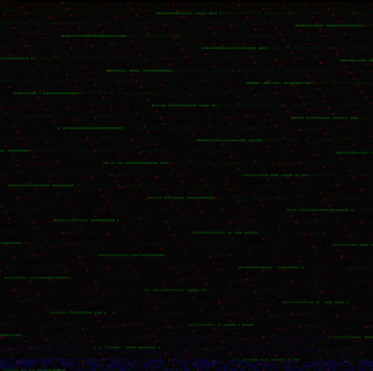
The following image is the difference between the default mapper and the new mapper in v053-pex4 inverse round-trip, all else being equal. This is gamma up 8 to show the small differences. Notice the green and blue channel values for the selected pixel (shown in bright green). Very small differences. Green is 0.0000012, blue is 0.00000024. The selected pixel represents well the other pixels visible in this image.
I have a few questions about the ACES 2 candidates, hopefully I’ve got the right place to ask these questions.
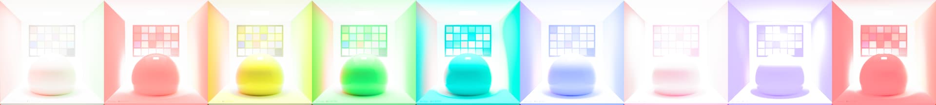
For the Baselight v052 candidates on Github I noticed that there are only two viewing conditions set under the .fltransform, but there is more .cub files than that included in the package. Is it recommended to only use those two at this point? or should the user manually add other entries.
I’m also curious if there is documentation on the naming. For something like “ACES2_Candidate_CAMDRT_rev052_P3D65.cub” is this supposed to be P3 D65 2.6 Gamma or P3 D65 1000 nit? Apologies if this is an obvious question as I am new to ACES.
What are the Rec 709 sim transforms meant to be used for?
ACES2_Candidate_CAMDRT_rev052_P3D65 (Rec709 sim).cub
ACES2_Candidate_CAMDRT_rev052_Rec2100 (Rec709 sim).cub
Pending the answer to #2, I’m curious if there is a plan to include the full family of transforms for Baselight similar to what is available in the Trulight Cam transforms (108 nit theatrical for example). Also, will the final release to baselight be baked down cubes as they are in this candidate?
Lastly, I believe there is a typo in the FL Transform
Forward = “ACES2_Candidate_CAMDRT_rev052_Rec2100.cub”,
Inverse = “ACES2_Candidate_CAMDRT_rev052_Rec2100 (P3D65 1000nit Limited)_inverse.cub”
For the forward transform, there is no .cub with that name.
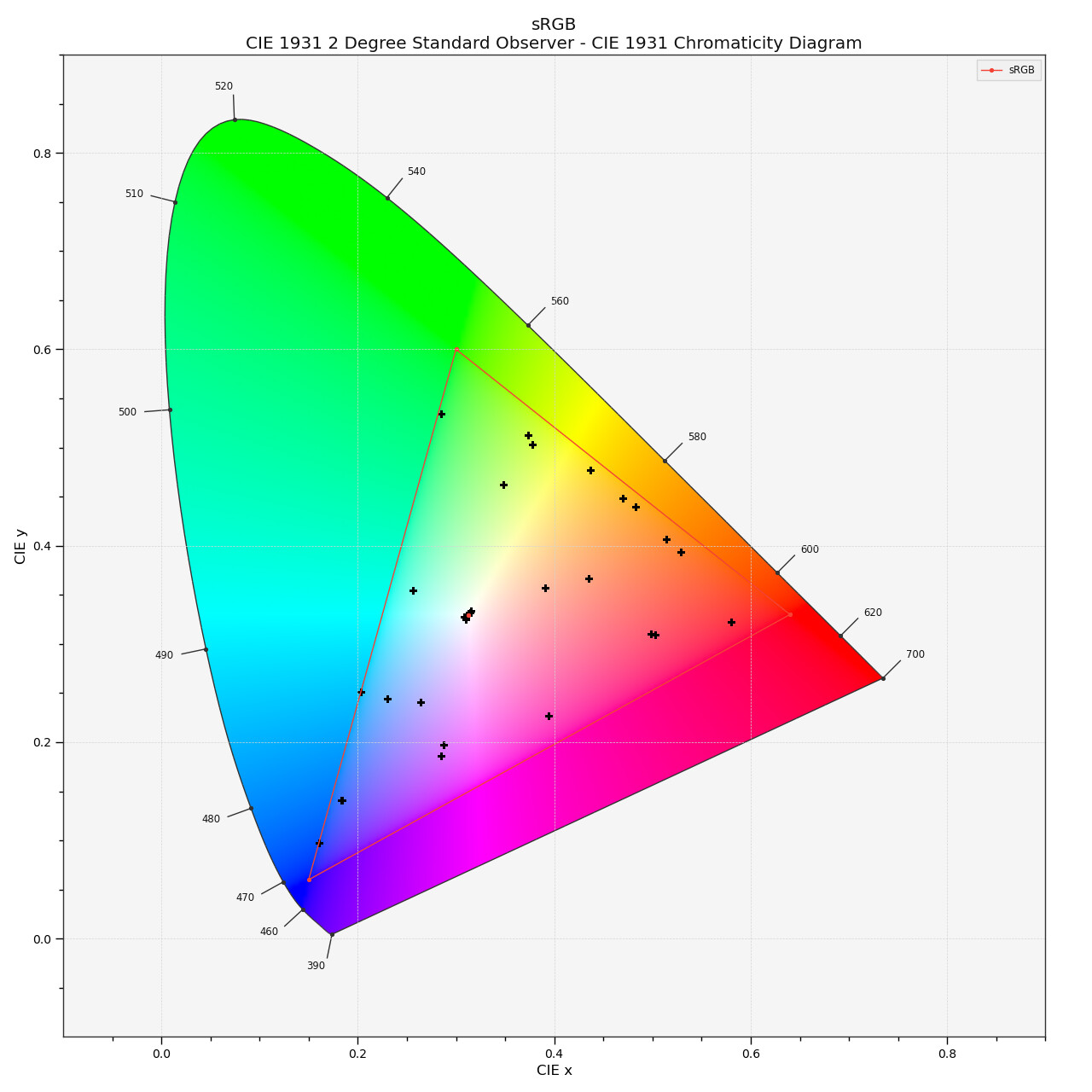
At last I wanted to see how the patches shift with the ACES 2.0 candidates.
I tried the v052 over OCIO and v053 directly out of the nuke node.
The plot is in both occasions somehow different to the other plot above.
After a while I realised that there is a plotting + symbol also in the lower left corner of the plot.
It’s best visible by enlarging one plot and flip through them. The filename shows what is what.
First I thought this might be an error from the OCIO lut bake, but it’s not.
Do you have any idea what this plotted + in the corner could represent in the data?