Interesting.
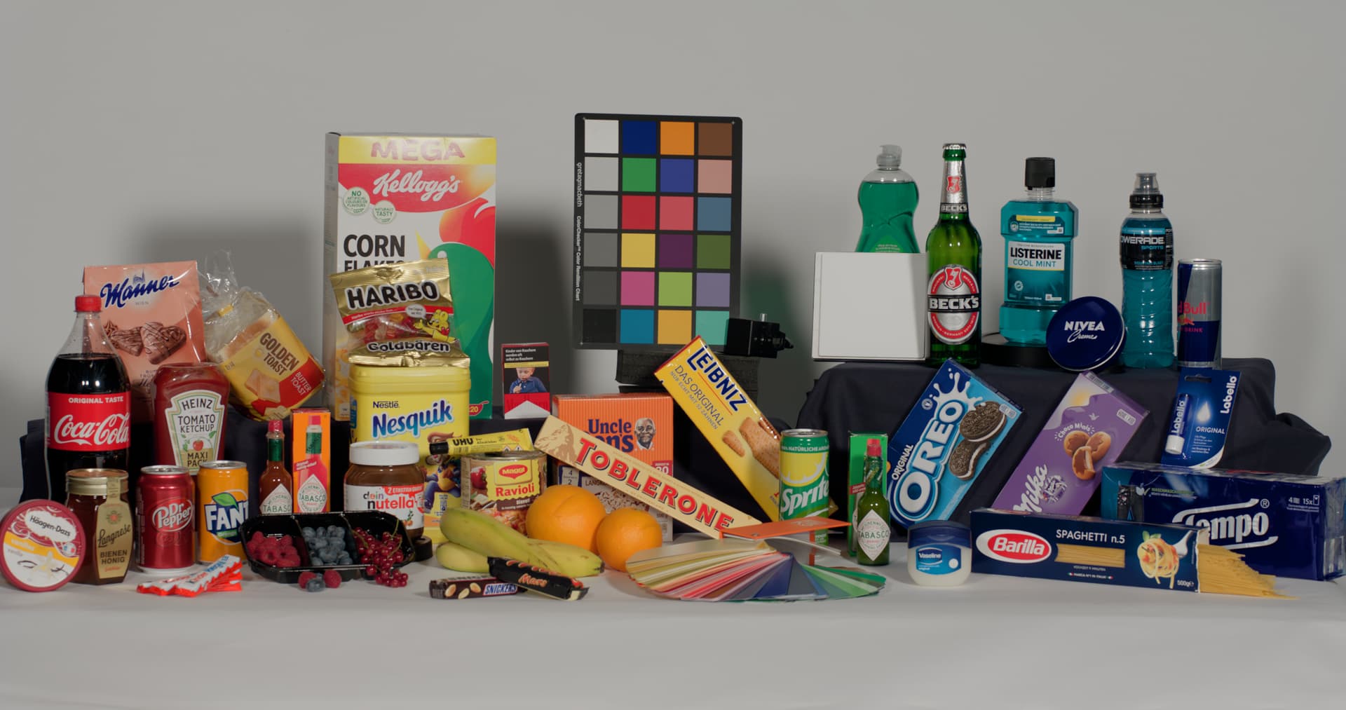
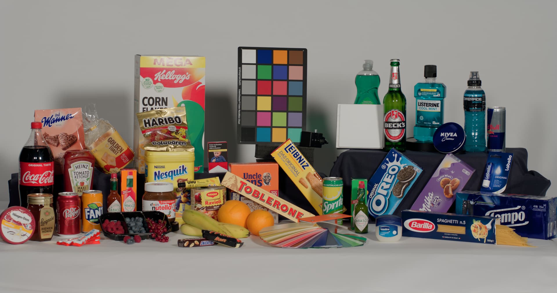
I’m guessing, but perhaps there is a NaN being produced somehow. Can you find what pixel in the ColorChecker image is producing that, by cropping the image until it disappears?
Interesting.
I’m guessing, but perhaps there is a NaN being produced somehow. Can you find what pixel in the ColorChecker image is producing that, by cropping the image until it disappears?
@alexfry should confirm, but I believe the LUTs used in the Baselight version are just batch converted from the LUTs used in the OCIO and Resolve versions, but because Baselight’s colour management is more flexible, they are not all actually needed.
The posted .fltransform file only contains two viewing conditions. But there is no reason you can’t edit it to add others that LUTs are provided for.
That is P3-D65 gamma 2.6.
These are not used. The LUTs are the Rec.709 rendering encoded in the other display spaces, so a monitor can be set to Rec.2100 PQ or P3-D65 2.6 gamma and show the Rec.709 rendering, to enable toggling between different renderings without changing the monitor settings. So “simulating Rec.709” on a different display.
But these are not needed with Baselight, because although by default the appropriate transform from a DRT family is selected automatically based on the Viewing Colour Space, you can manually choose e.g. and SDR rendering in an HDR Viewing Colour Space.
You are right. That is a typo. The forward transform .cub name should also include “(P3D65 1000nit Limited)”.
I will try. At a first glance I don’t see any unexpected values.
After I cropped the next out and only used the patches, the + is still there. No change yet.
I don’t see the cross in the bottom left when I plot your EXR:
I am plotting every pixel. You appear to have pre-processed it to reduce the number of samples. Is it possible something has happened there?
For reference, here is a plot with just the 24 patch values from your EXR, removing the patch edge anti-aliased values.
Thanks for checking the file @nick.
I am not sure what and where, but it seems I make a mistake somewhere on the way. This is the first time that I noticed a + where it does not belong. I will write you a direct message, maybe you can tell me how to plot the last image you made.
In the end I only noticed that something was off because the graphic of the wavelength numbers changed in size from plot to plot.
Still it’s interesting to see how the patches shift depending on the chosen image formation.
I am coming to the conclusion that small discrepancies near zero in a round-trip may be an inevitable consequence of forward/reverse matrix operations. And then the inverse BT.1886 EOTF turns a negligible linear difference into a noticeable code value difference.
I just tested two Nuke ColorSpace nodes back to back, one going sRGB 2.4 gamma to XYZ and the other doing the inverse. That doesn’t round trip perfectly. Cyan [0.0, 1.0, 1.0] becomes [0.0022, 1.0, 1.0]. That’s a difference of two 10-bit code values, just going to XYZ and back.
It actually already happens with the current OCIOv2 implementation of the ACES 1.3 display transforms. [0.0, 0.5, 1.0] round-trips to [0.00107, 0.5, 1.0] using OCIODisplay in Nuke with the Rec.709 Output Transform. And I do not believe that is one of the values that should be impacted by the non-invertibiity of the RRT sweeteners.
A similar (but for different input) error happens wit @jedsmith’s Blink implementation of the ACES Output Transforms. [0.0, 1.0, 0.75] round-trips to [0.00220, 1.0, 0.75].
If current implementations of the relatively simple forward/inverse Output Transforms cannot accurately round-trip (discounting the non-invertible region) then it seems inevitable that the new version, with its more complex processing and multiple colour space conversions, will suffer the same effect.
I think if the imprecision is only noticeable when pixel-peeping at exact code values, but not visible on a display or waveform monitor, it is probably not a problem.
Yes, and the latest CAM DRT, regardless of which mapper is used, inverts clearly better than ACES1 (even with sweeteners disabled).
I have been doing some further investigation into where these small round trip errors creep in, using @priikone’s v53_pex4. In a 17^3 unit cube, the colour with the largest round-trip error is [0.0, 0.9375, 0.0].
Using Nuke’s debugPrint() statements at the various steps though the forward and inverse process, I get the following results:
// inverse transform
float3 srcRGB = 0, 0.9375, 0
float3 luminanceRGB = 0, 85.6507, 0
float3 XYZ = 30.6274, 61.2547, 10.2091
float3 compressedJMh = 69.0652, 71.6736, 136.472
float3 tonemappedJMh = 70.0035, 84.1431, 136.472
float3 JMh = 101.084, 121.587, 136.472
float3 dstRGB = 0.550096, 1.99705, 0.0747953

// forward transform
float3 srcRGB = 0.550096, 1.99705, 0.0747953
float3 JMh = 101.084, 121.587, 136.472
float3 tonemappedJMh = 70.0035, 84.1429, 136.472
float3 compressedJMh = 69.0652, 71.6736, 136.472
float3 luminanceXYZ = 30.6274, 61.2547, 10.2091
float3 luminanceRGB = 0.000249863, 85.6506, 2.86102e-06
float3 dstRGB = 0.00456816, 0.9375, 0
As can be seen, everything round-trips perfectly as far as the output XYZ of the forward transform. It is in the final conversion to RGB that a small linear error creeps in, and then the BT.1886 gamma amplifies that.
So everything we do in JMh is inverting perfectly. It’s the final matrixing from XYZ to RGB which introduces the issue (such as it is).
The XYZ to RGB matrix is calculated in the code as the inverse of the RGB to XYZ matrix, so the problem does not come from declaring matrices at insufficient precision. Would performing the matrix operations at 1.0 scale instead of 100 scale help? I am not sufficiently familiar with the limitations of floating point maths to know.
Since we have talked about creating a transform which goes from linear AP0 to display-referred XYZ, and leaving the final RGB encoding up to implementers, it could be argued that we have a perfect round trip, with no precision issues! But that is just kicking the problem further down the line!
Thanks for posting these results Nick! To answer one of your questions, no, normalizing differently (e.g. 1 rather than 100) will not help with floating-point math. However, if you’re not already calculating the inverse matrix coefficients at double precision (even if it’s applied at single-precision), that might help.
In OCIO, calculations are done at single precision, and in OCIO v1, the matrix coefficients were also kept at single precision. But as of OCIO v2, the coefficients for matrices were upgraded to double precision. And when we invert them, we do so at double precision, which we found helped. Here’s a round-trip of your same matrix conversion as separate processing steps in OCIO:
linear Rec.709: [0, 85.6507, 0]
linear XYZ: [30.62735, 61.25470, 10.20912]
linear Rec.709: [2.38419e-06, 85.65070, 0.0]
That was all with single-precision floating-point RGB evals.
But, as you know, the conversion from XYZ to RGB is essentially a saturation boost, and then applying the gamma is another boost. So both steps will be amplifying the errors introduced at previous steps.
I would recommend testing your setup by just applying the forward and inverse matrix and see how much difference you get. If it’s more than what I show above, try calculating the inverse matrix at double precision. If it’s already similar to what I show above, then I think your round-trip to XYZ is actually not perfect and whatever small amount of error is simply gained up by the matrix (as well as the gamma of course).
Nick, regarding your comments about the ACES 1.x inverse, the [0.,0.5,1.0] test value you used is actually impacted by one of the known bugs in those algorithms.
As I mentioned during the working group meeting two weeks ago, several of the “harmless” tweaks that were made to the look in the final weeks of development wound up breaking the inverse. One was the change to the red modifier and the other was the introduction of a saturation modifier. Inverting colors that have one or more components at 0 or 1 are known not to invert cleanly due to the saturation-related bug.
Moving even a small way inside the gamut allows for a much better inverse. So, for example, in OCIO a Rec.709 value of [0.02, 0.5, 0.98] round-trips to [0.020089, 0.499996, 0.9799951], which is not perfect, but better than your results on the gamut boundary suggest.
(And sorry for not being able to attend the working group meetings regularly, the 1 pm PST time conflicts with two separate ASWF meetings.)
Unfortunately BlinkScript does not seem to be geared up to work in double precision. When I change the working variables in the matrix derivation to doubles instead of floats, Nuke instantly crashes with a seg fault when I recompile.
Maybe getting a bit confused with all the various depositories in GitHub. Are the most recent transforms at GitHub - ampas/ACES_ODT_Candidates ?
If so I am getting a lot of saturation compared to previous versions. Also could instructions for using these in DaVinci Resolve be restated. Since the iPad can only still add DCTL and not ACES transforms can I still just remove the first line to make them work (this was working well before and want to know if still valid.) (I am testing on both AMD system with Decklinked OLED TV and the iPad Pro in Reference Mode, SDR and HDR versions of ver053.)
Also, is the timeline space now AP1 which I thought originally was AP0? Maybe I have the settings mixed up which gives the saturation issues. Thanks
That’s the correct repo. I tested v053 Rec.709 DCTL and I can’t see any issues compared to previous versions. That was with normal ACEScct color managed setup in Resolve.
After testing with ACES v053, I have a few observations.
It seems very good overall and many artifacts are resolved by using ACES 2. The match between SDR and HDR is much better. My main concern, if I’m using the correct terms, is that both the gamut compression and chroma compression seem quite aggressive compared to ACES 1. Is this something that can be backed off without causing artifacts? I am viewing images on a Sony x310 in HDR.
-Very saturated looks are a fight in v2. Saturated colours start blowing out and going bright rather than becoming more saturated. Certain projects I work on would be fighting this gamut compression.
-Reds look more pink and desaturated than red/orange and saturated (fires, stop lights, many of the ACES test images). It easy to desaturate extreme colours or bleach highlights, but it is hard to get that back once the colour is gone.
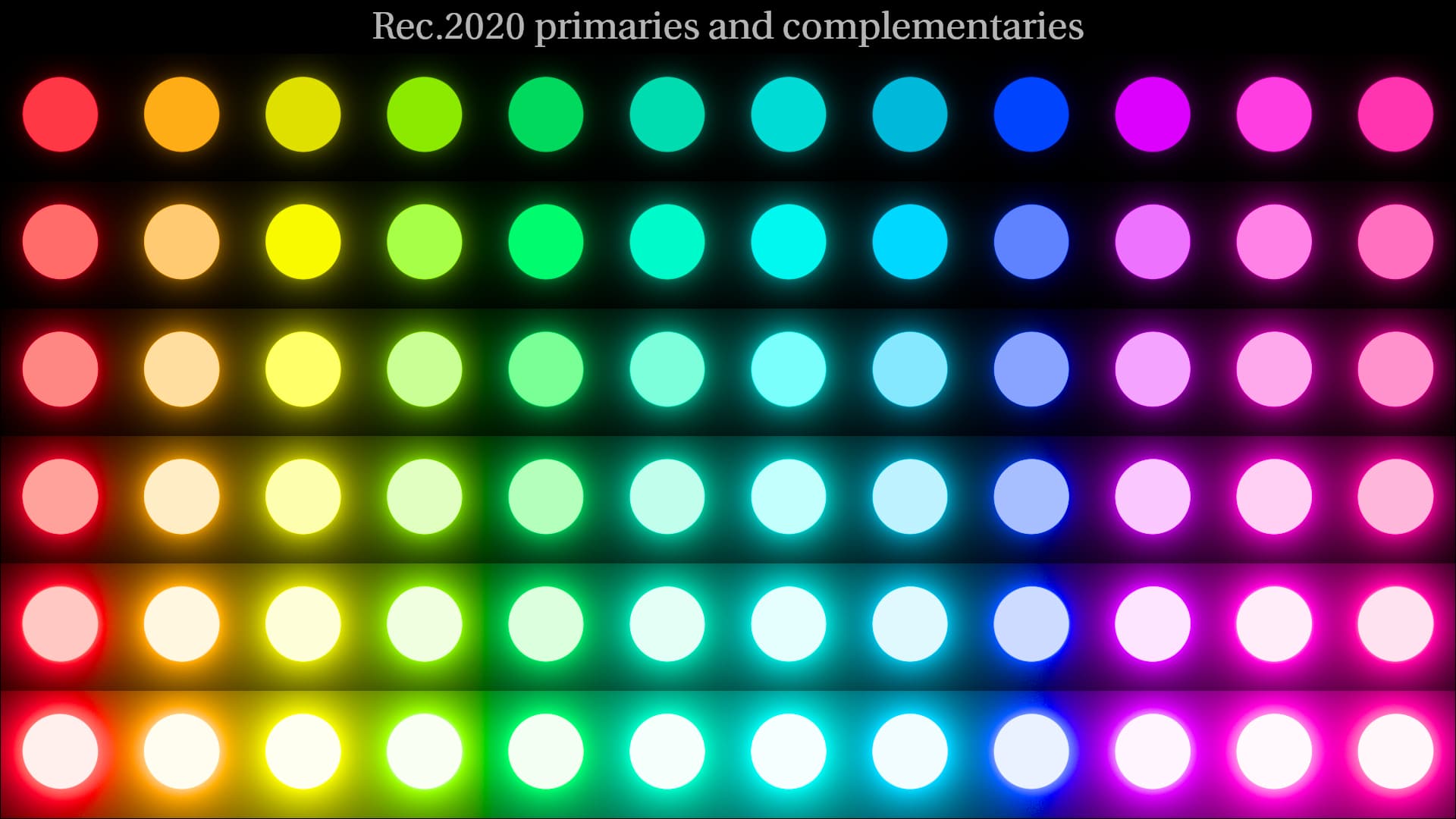
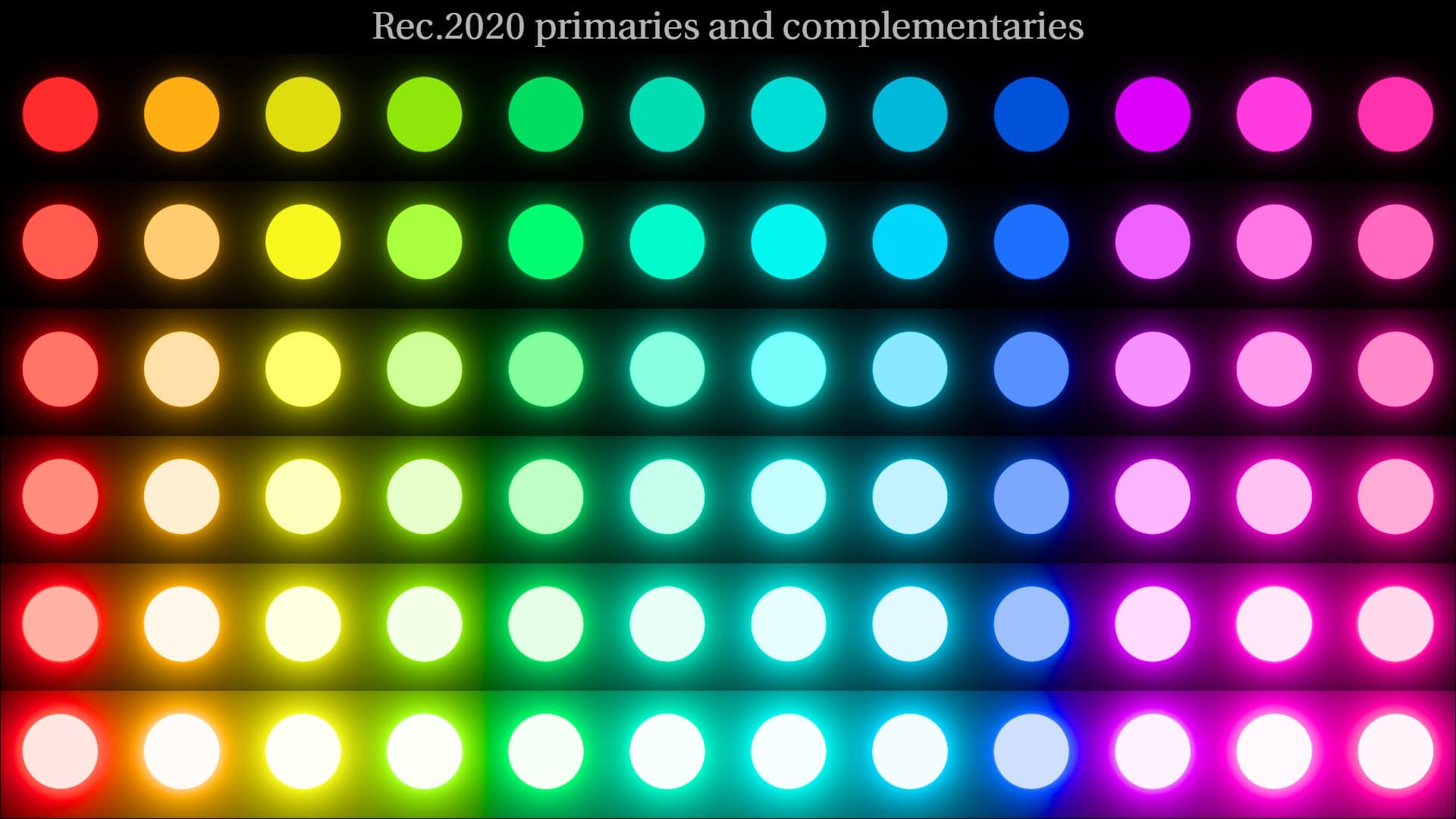
-Strong pure blues don’t seem to exist. They are very desaturated and swing towards different hues. In the ACES test shots this is most noticeable on the rainbow board of circles, the rainbow balloon, the frontier casino sky, and the bluescreen shot.
Thanks for taking the time to test, all feedback is useful. I would say your feedback is in line with what we’ve received so far.
This is what we’ve heard before for Rec.709 100 nit transform, especially for reds, and blues as you also mentioned. Are you saying that you’re seeing same happening also with Rec.2100 1000 nit transform? One way to retain that saturation is to darken highly saturated bright colors in Rec.709, but so far based on my own testing it shouldn’t be necessary in Rec.2100.
For some highly saturated blues ACES2 is still going to need the RGC (Reference Gamut Compressor), like with the blue screen image you mentioned.
I guess the follow up question is, are you able to color grade with it to get the colors where you want?
Here is one more attempt at changing the transform so that we can retain colorfulness better in SDR and have smoother gradients. What I learned almost a year ago with the Alternative compress mode is that the reason why blue and red desaturate so quickly (and contribute to poor gradients) is partly the compress mode, and not the gamut mapper alone. In that thread I went over why we need the compress mode, but I now believe there is a way to entirely remove the compress mode from the transform.
I’ve done that as CAM DRT v054-pex1 experimental version, available from my repo under that name, as well as Rec.709 and Rec.2100 LUTs and DCTLs, available under the LUT directory. It does the following:
This brings the following (IMHO) positives (and no negatives that I have seen so far):
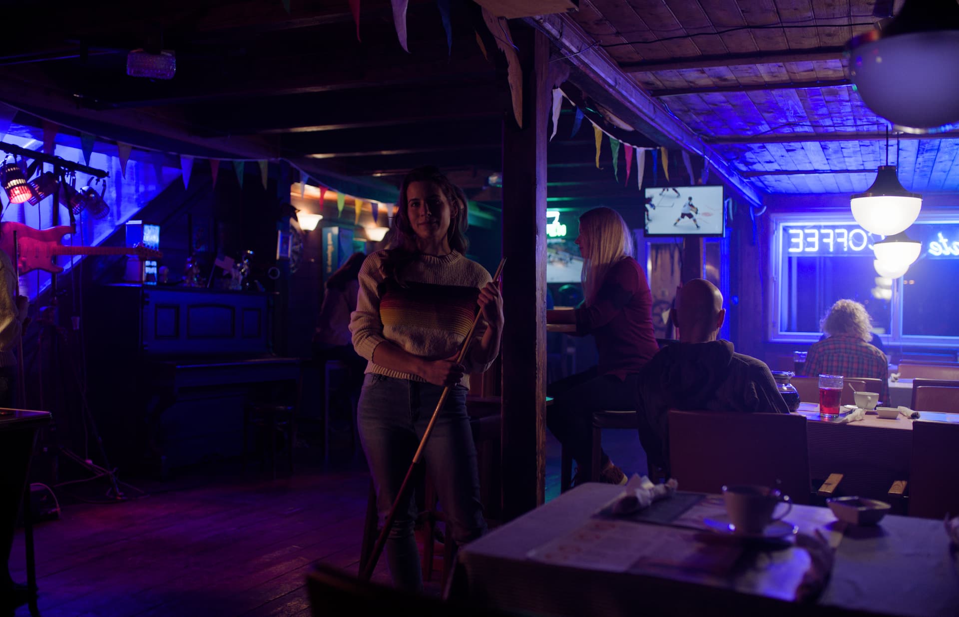
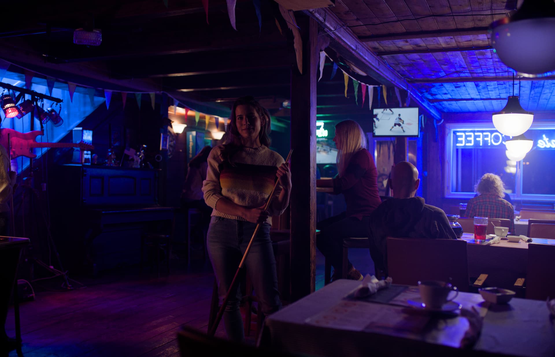
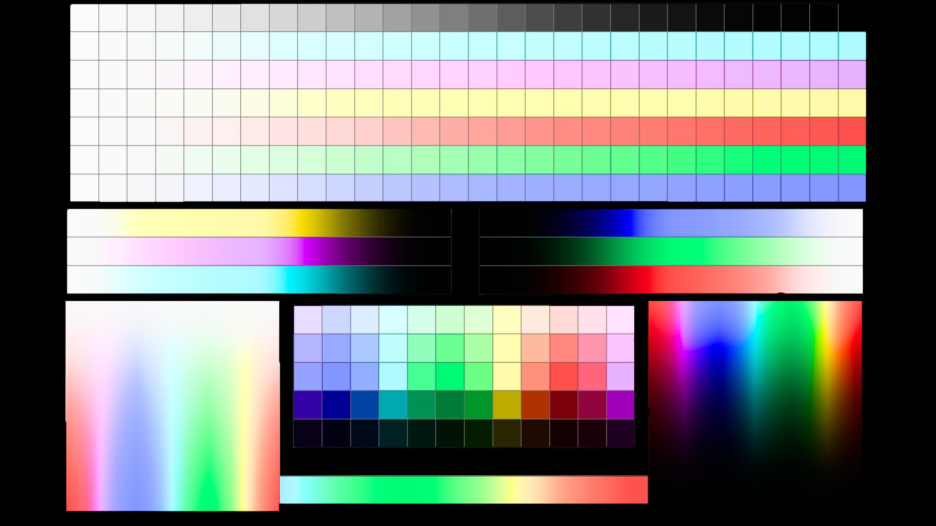
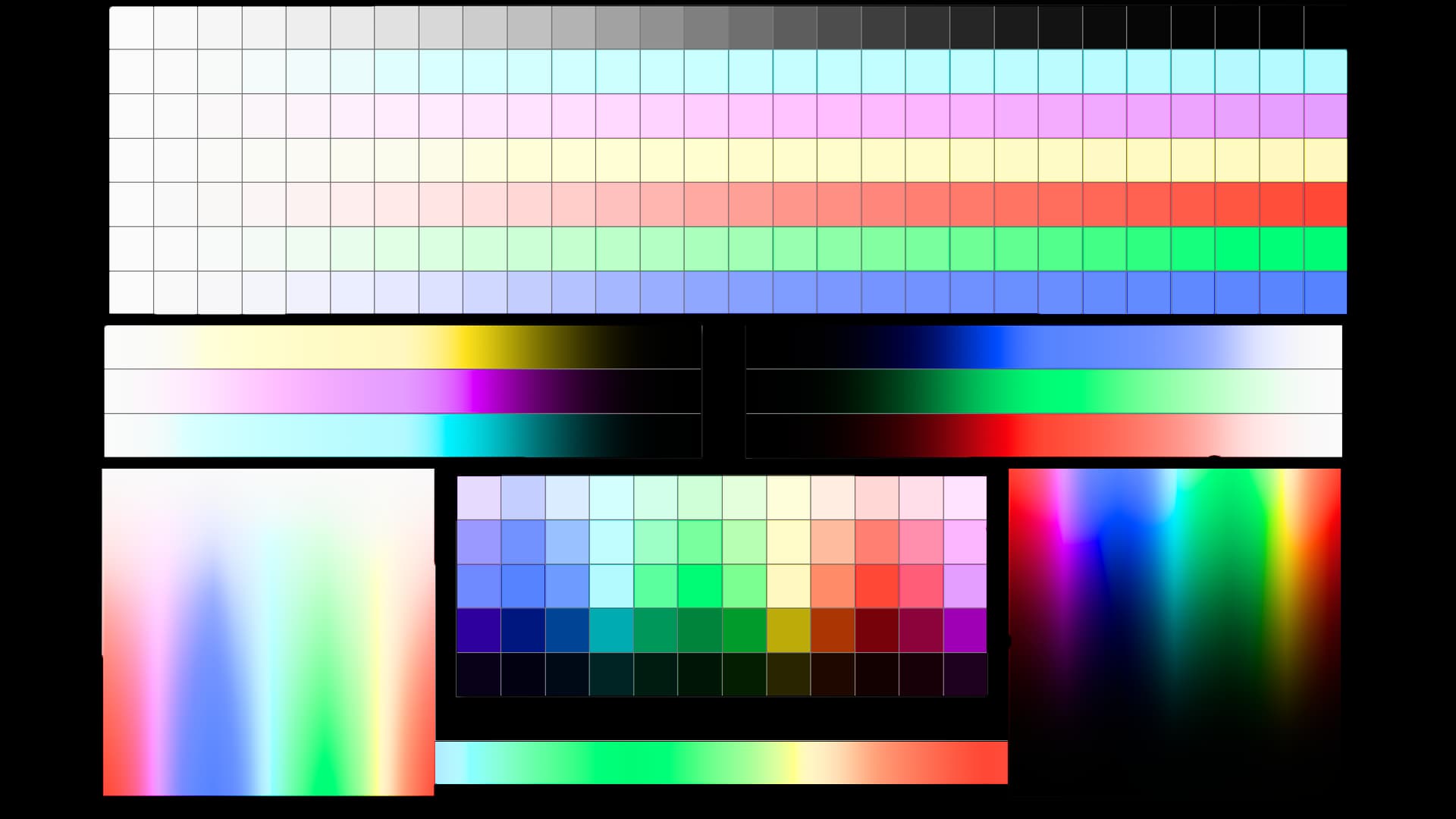
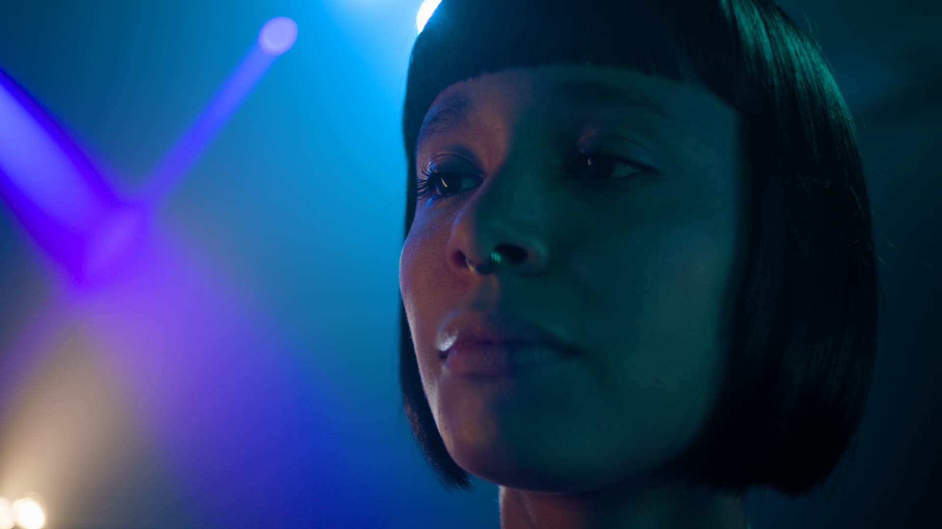
I’ve tested this with both SDR and HDR. This was a quick test and with small parameter adjustments it can be improved more. To my eye the match is markedly better with highly saturated colors, especially in images like the Blue Bar (good match), and in the color gradient images (improved match).
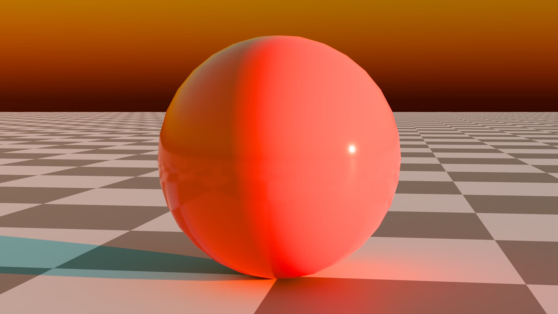
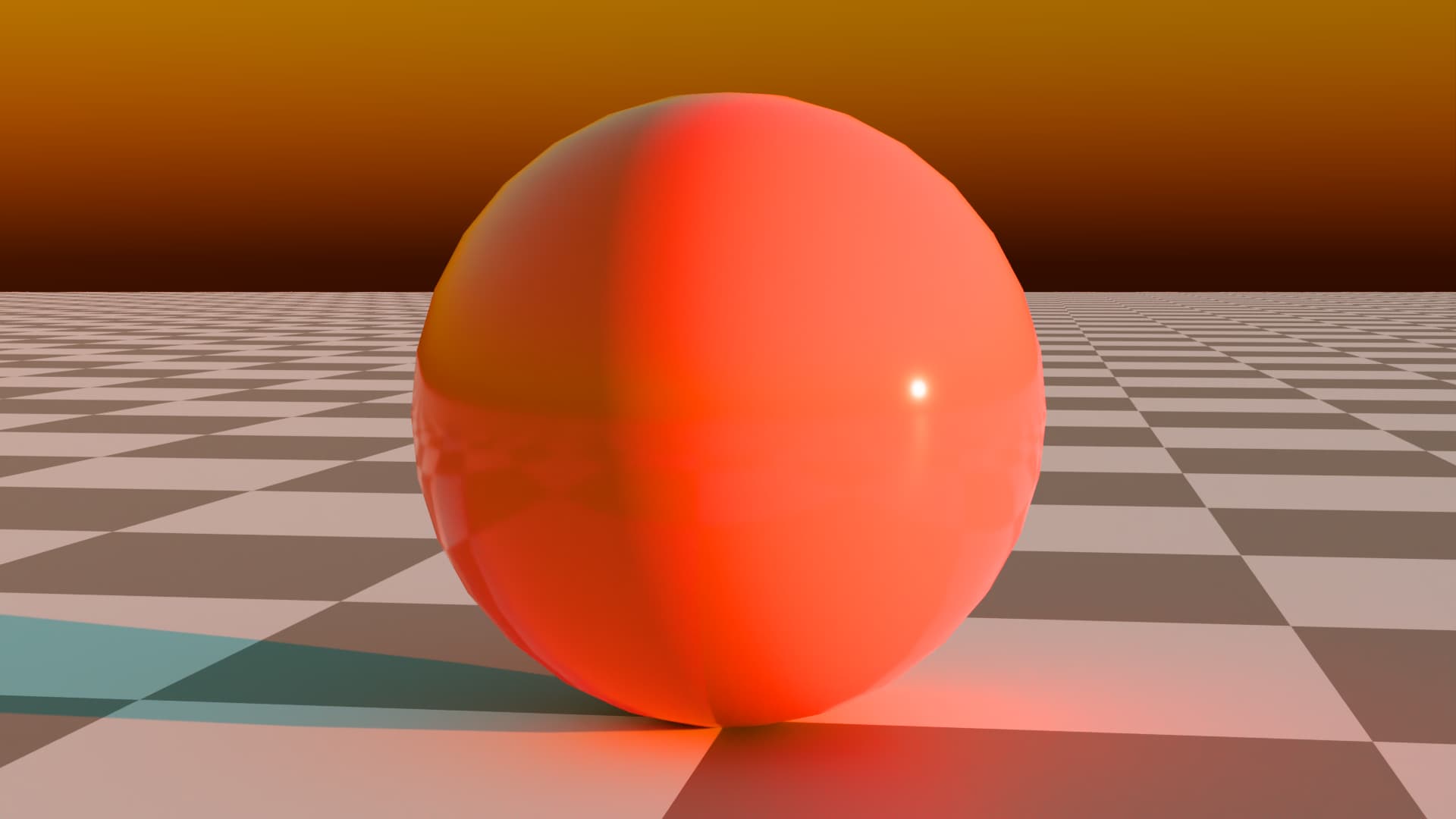
Below are images of v053 sRGB vs v054-pex1 sRGB, in that order.
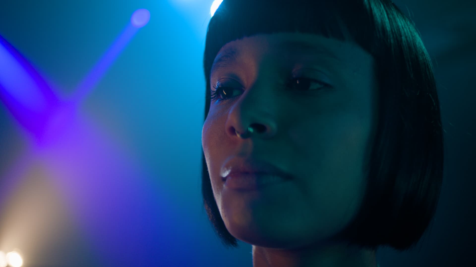
Thank you for all the hard work! Some gradients look better and some look worse. For example, the wall in this picture have much smoother gradient now but blue reflection on the table is more saturated.
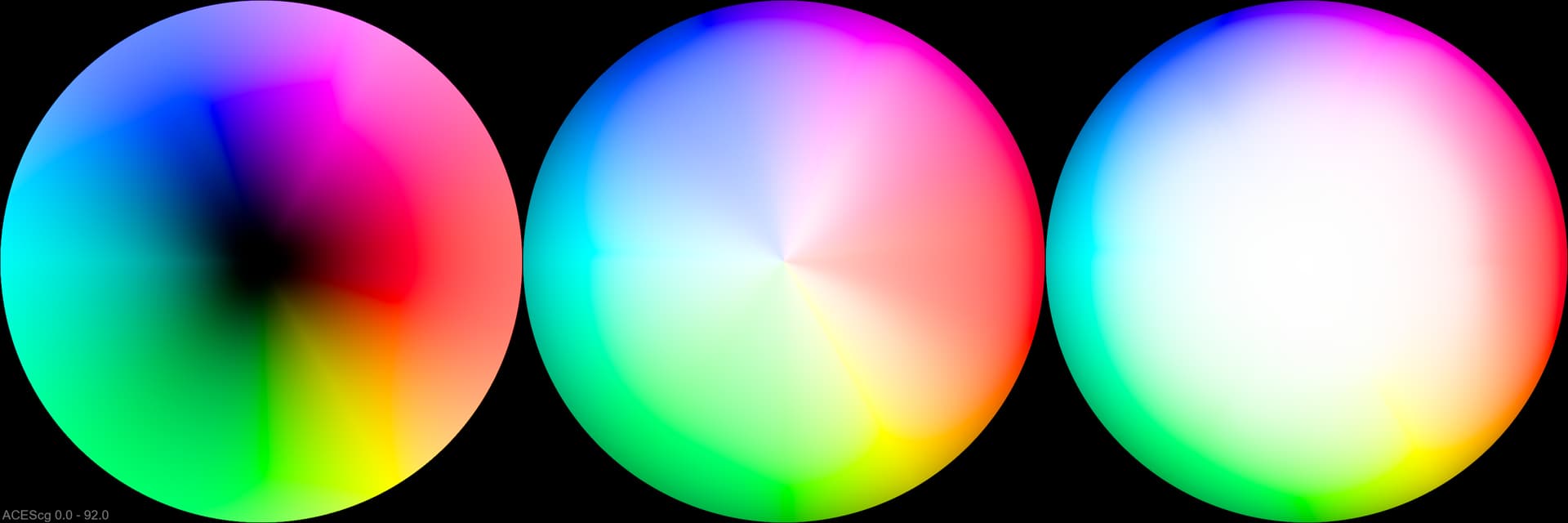
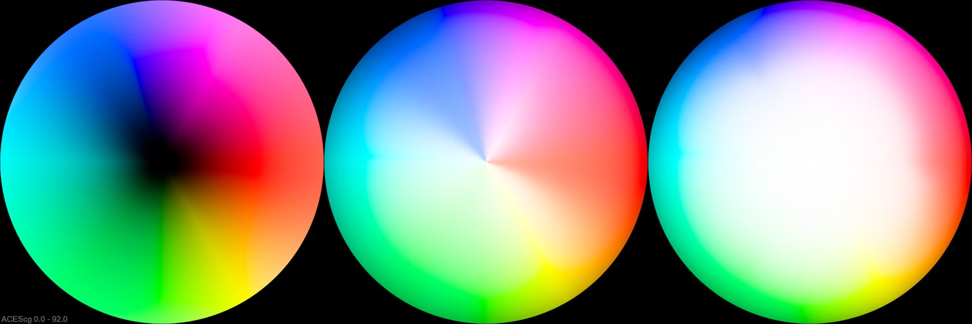
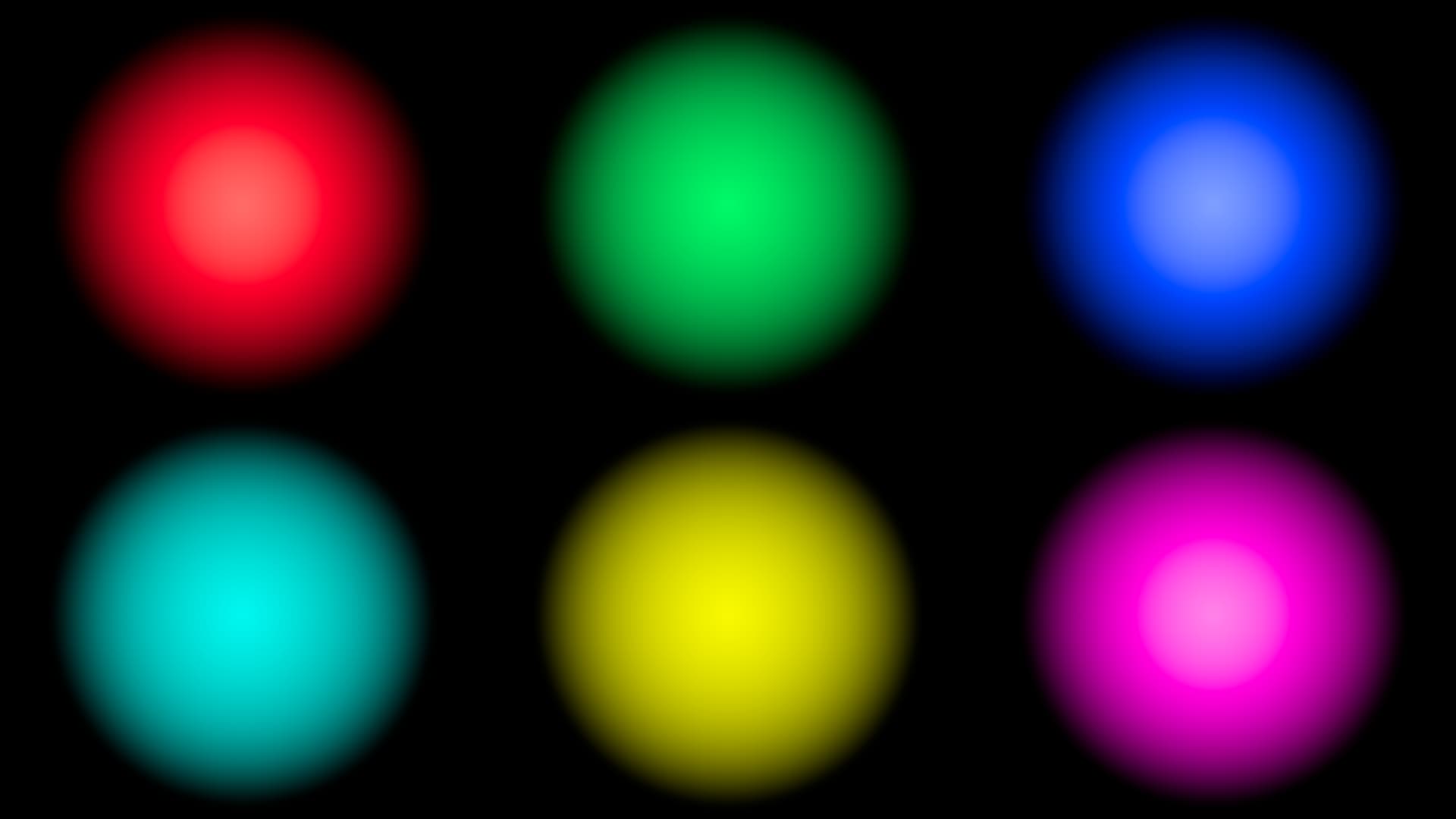
Blue orbs have smoother halos in the new version but overall brightness and peak brightness (!) is lower. It can look really weird in a real image.
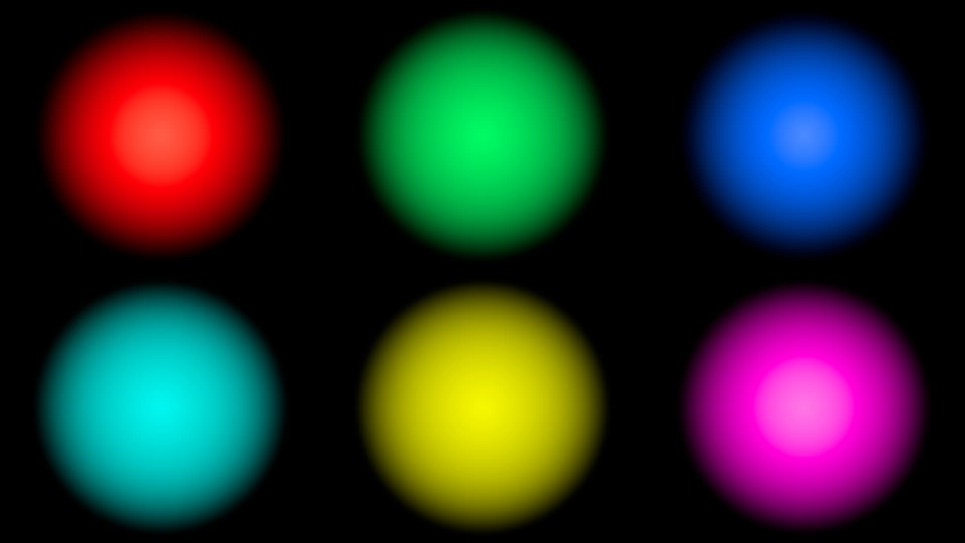
Same with the red orbs.
rev054 from Pekka looks good to me and better then rev053. I would like to have the rest of the 2100 ST2084 set this way… but hopefully will get them soon as DCTL rather than LUTs.
I am not sure about the overall and peak brightness issue mentioned by Fedor as the “real” images of the sample group look pretty good with blues and reds not looking out of place… but will pay attention to this. And keeping in mind that these are LUTs which can break towards extremes… but I feel adjustments can be made to these two rev054 better than most previous versions.
I am still wary of baking a clamp like this into the transform, with its resulting scene space skews.
Clamping the input to AP1 is easy for the user to do. It could even be part of a default LMT if it was felt desirable for the “out-of-the-box” look. But putting it in an LMT makes it easier to switch off for those who don’t want it. And there’s always the RGC…
That’s an important point. Extreme images may well include values which are not covered by the LUT shaper.