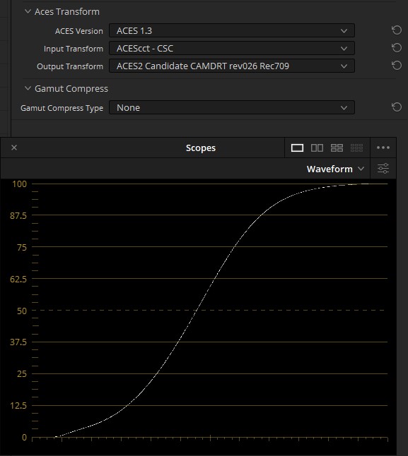
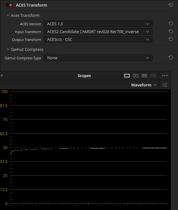
I probably missed something, but seems like .dctl inverse doesn’t work as it should. I mean inverse should go into IDT folder, but in this case it doesn’t look like an inverted S-curve that is expected (with the log csc on the other end of course), but almost like a horizontal line instead.
If I get it right, at first should be a LUT, and after that the conversion to Linear AP0, but it has the reversed order now.
Uses the “live from params” by default with the values set to new primaries that gets greens and yellows closer to Hellwig model (without Compress Mode), and improves blues. Blue gets lighter and the blue-magenta skew is reduced. Greens will get a bit darker and yellow/orange a bit more saturated.
Changes gamut mapping compression to use 1.7 for limit and 1.9 for power. This improves gamut mapping result especially in shadows, reducing the chance of skews. It does affect pure colors a bit, with blue and red getting a bit lighter.
Changes the shadow_boost control (inside the kernel) to automatically scale with peak luminance (affects SDR/HDR match)
The largest impact to color rendering comes from the new primaries. They skew especially greens more closer to where Hellwig model has them out of the box.
@meleshkevich I’ve updated the repo to now have proper inverse transforms for Resolve (Under the IDT subdir). Thanks to @nick for providing the DCTL structure.
Although I left my dongle a work, so if you’re able to give them a quick test that would be great.
Also added @priikone’s new v027, forward and inverse.
(Update: Forgot to hit save on the inverse DCTL template, updated repo, thanks @nick )
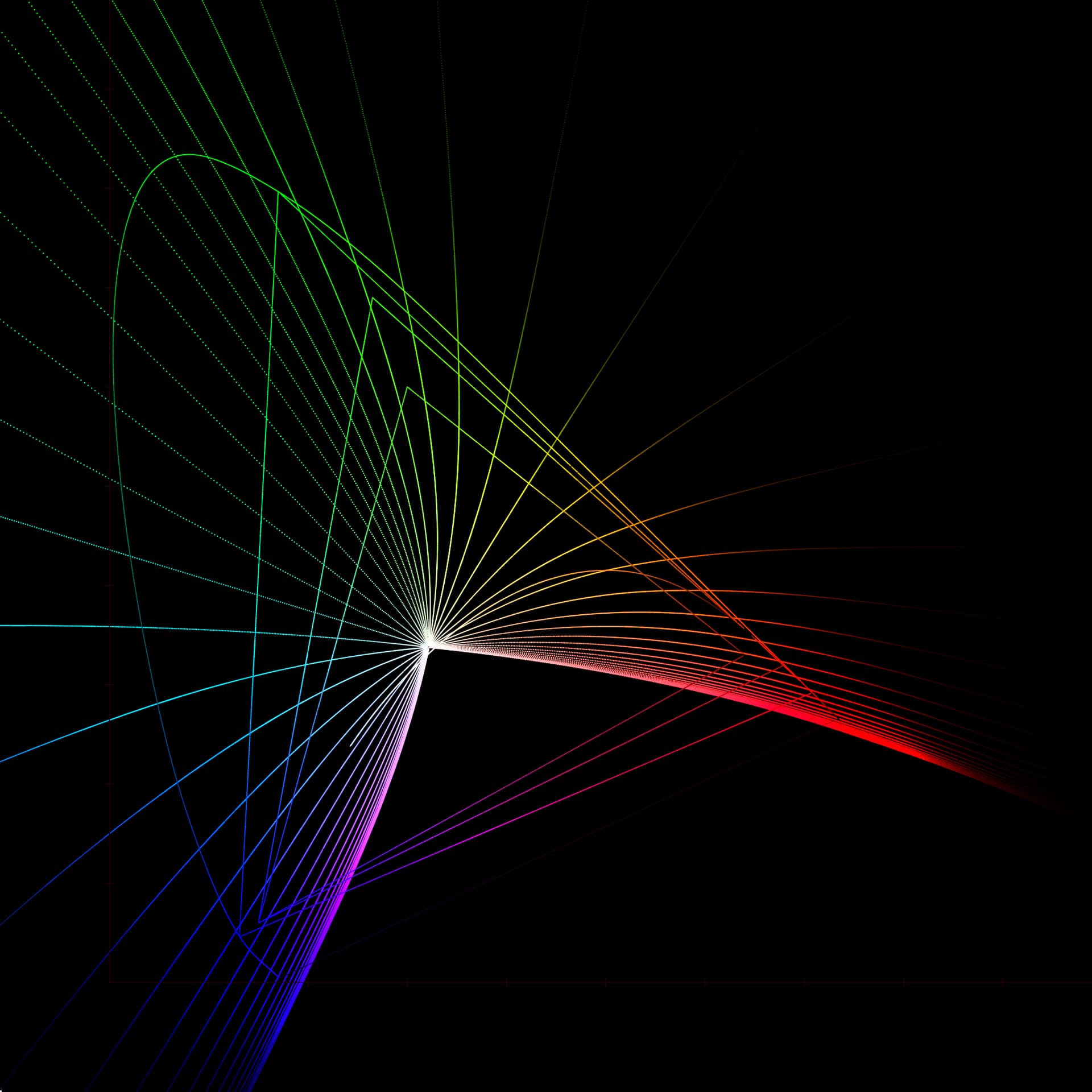
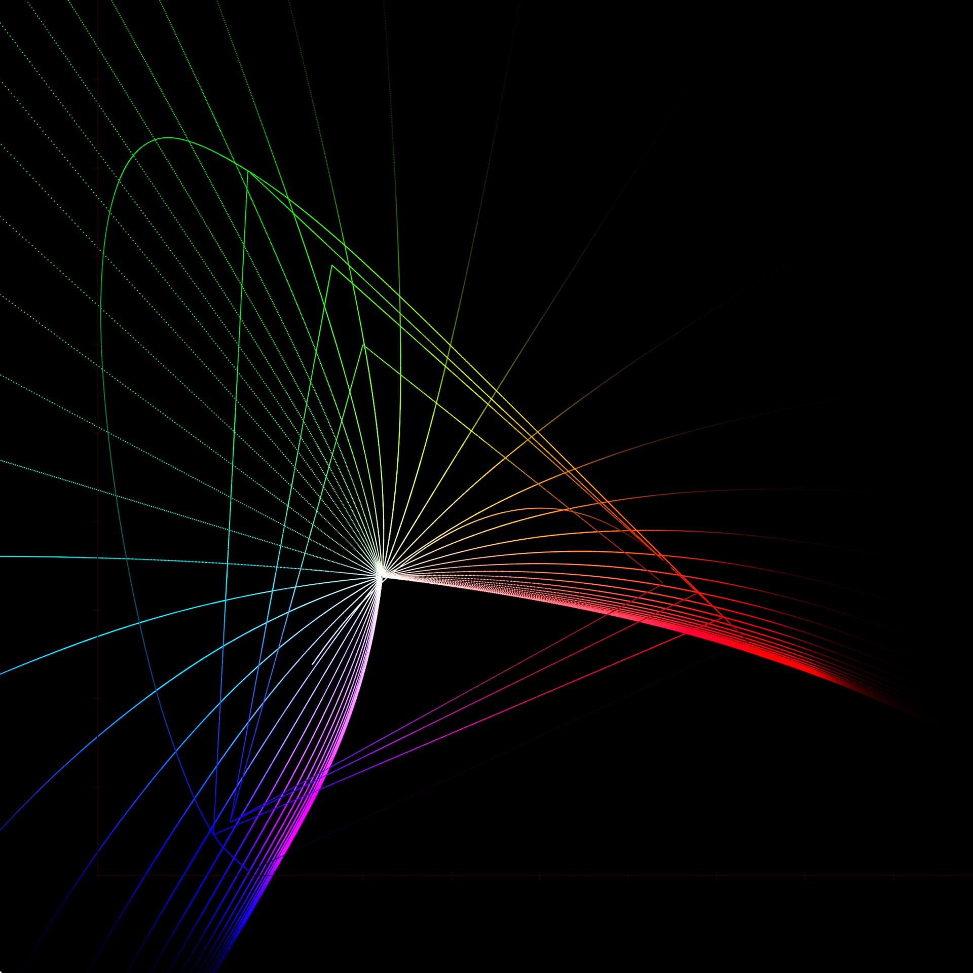
I guess, these artifacts are coming from the implementation that uses LUT, and with the actual code it will be smoother?
It’s Inverse DRT to ACEScct to DRT
I haven’t checked that image recently but the current gamut mapping result is not entirely smooth. As for inverse it does invert Rec.709 display cube in and out. The question is whether the inversion is sensible in the working color space. One thing that the new gamut mapping compression params (in v27) do is that it increases compression, which will have negative impact for the inverse. Inverse will end up pushing values more outward. So I think the new params should be a temporary solution to the channel clipping in the shadows.
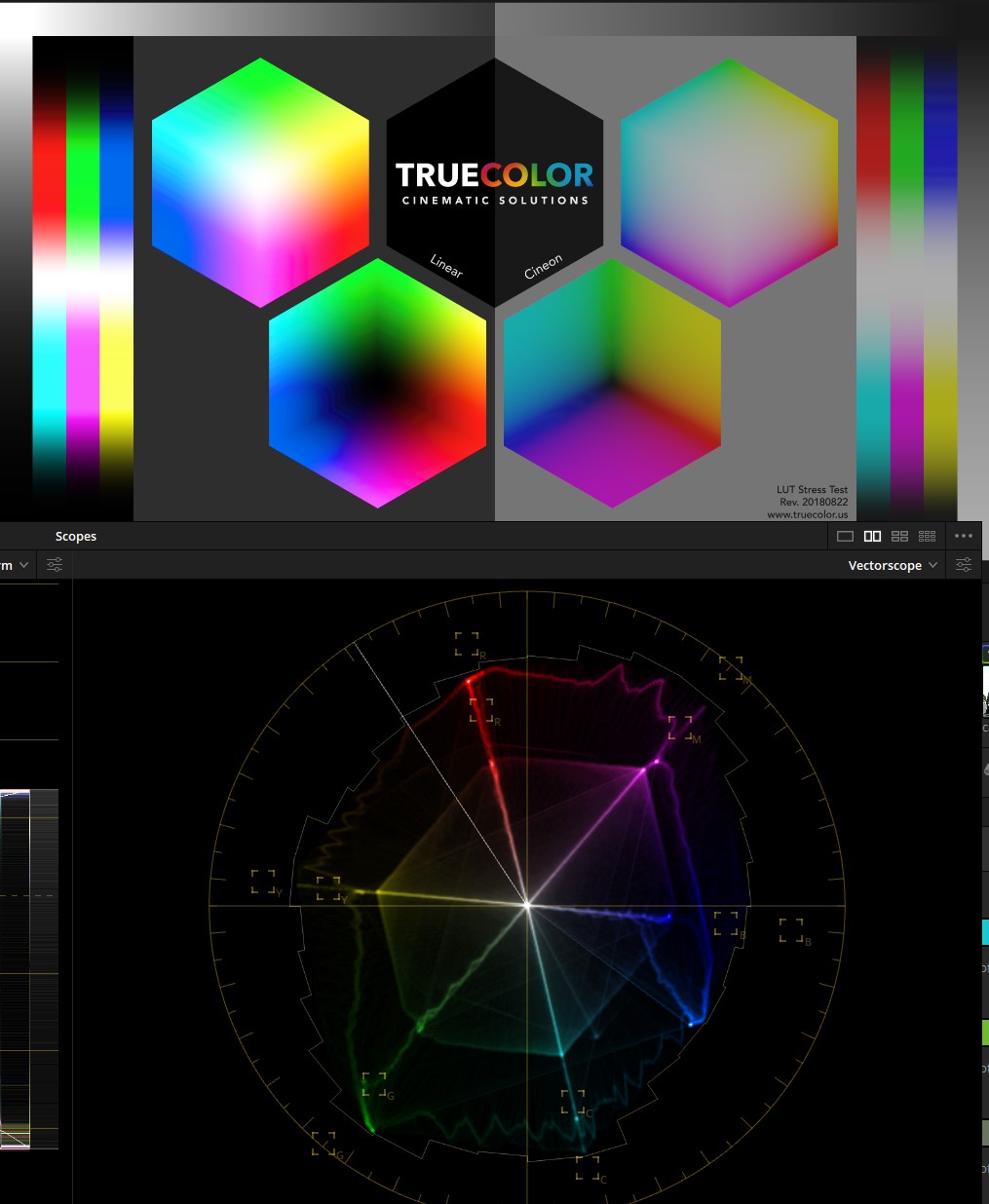
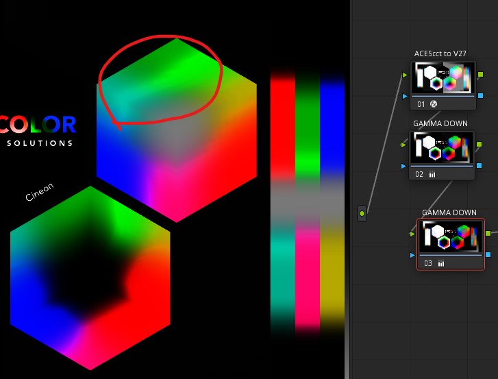
I doubt this stress testing is relevant at all, and for sure it is not something scientific, so this is just from a user perspective. I was curious how smooth is v27 in the highlights so I applied it to the image using ACES Transform with ACEScct set as input, and made the resulting image darker with gamma wheel.
Everything looks as expected for me, except for this region. It goes from the darker greens to the brighter, and then to the darker again.
Maybe this is what it should look like at the current stage of development, so I decided to mention it just in case.
Overall, V27 feels almost ready for the actual use in real projects. I’m talking about SDR only, don’t have an HDR display with the acceptable black and white levels.
I really like its “path-to-black”. Sometimes it behaves a bit unexpected, but adding RGC (in its default state) after all the grading and before DRT helps with those issues and the darkest regions become very nice and smooth.
But most important is that I can lower flare level now (with v27) without a need to constantly eyeball for the artifacts, that may become visible on some displays.
I have been looking at some smooth gradients, Grey, Resolve’s four color.
Concerning the most recent versions 026 and 027:
One thing I am noticing is that the versions for both 026 and 027,
Rec2100 (Rec709sim),
Rec2100 (P3D65 540nit limited),
Rec2100 (P3D65 1000nit limited),
all look to have banding, whereas the SDR Rec709 versions do not.
Also this banding is not noticeable (or very little if it is there) in previous versions 024, 025.
As to comparing the latest 026 and 027
Rec2100 (Rec709sim) vs Rec2100 (P3D65 540nit limited) [called HDR below]
as is with no grading, comparing 4 at a time in split screen:
027 might have an edge in overall look and matching, however there are still differences as the following:
0067(Isabela) - Both Rec709sim look to have a magenta cast in the shirt which seems to be closer to the intended blue in the HDR.
0005(trumpet player) - The dark skin and the Brass color look more real in the HDR than the Rec709sim. This seems to be a reddish tint in the Rec709sim.
0029(laundry) - All the colors vary in all four, but vary most between HDR and Rec709sim.
Also, another check using the two computers showed that the Rec2100(Rec709sim) and SDR Rec709 were fairly close for 0026 and 0027.
As to the inverse for both 026 and 027 with Rec2100 (Rec709sim), Rec2100 (P3D65 540nit limited) and Rec2100 (P3D65 1000nit limited):
Setting up a node with each of the six variations and then turning it on and off showed differences which would indicate that the inverse is not an exact inverse or there is some clipping somewhere.
Testing SDR/HDR match of v27, which I think is closer than older versions, I think I’ve noticed couple things related to the tonescale. I’m noticing that the lifting the middle gray from 100 nits to 1000 nits is maybe a bit too much. It’s a nit higher than where Jed’s original curve had it (though it matches ACES 1). Another thing I’m noticing is that shadows feel lifted in HDR in most images. I think the “flare” we have for 1000 nits is a bit too much compared to 100 nits. Ideally we’d have an offset control for flare but it’s currently driven mostly by the w_g. Higher the middle grey offset is more it lifts also the shadows.
The best compromise I was able to find is to lower w_g to 0.12 or 0.125 from the current 0.14. That brings the middle gray for 1000 nits where it was in Jed’s curve and lowers a bit the amount of lift in the shadows in HDR (SDR doesn’t change). To my eye it improves the match between the transforms, though I’d still like the lift to be less. I’m not necessarily suggesting that we change the tonescale anymore, this is more of a report of my testing.
When I look at v27 on my LG C1 48" OLED (admittedly not a reference monitor) I do not see any more shadow detail at 1000 nits than I do at 100. What monitor are you looking at @priikone? Is it possible that your monitor has some clipping at the bottom end, and simply lifting the mid grey point to 15 nits from 10 is raising some of the shadow detail out of the range that your monitor is clamping?
On a separate subject, I was thinking more about the discussion in last night’s meeting about gamut compression inverting Rec.709 to values outside AP1. It seems to me that this is an inevitable consequence of having a gamut compression in the DRT capable of bringing out of gamut values like those in Blue Bar to within the display gamut. Inevitably an inverse of this DRT is going to map values near the display gamut to extreme out of gamut values like those in Blue Bar.
For the same reason that it is hard (or impossible) for standard grading tools to bring those out of gamut values into AP1 (hence the need for the RGC) it is hard (or impossible) for those same tools to grade AP1 values to the extremes needed to render to the display boundary through the DRT.
So I come back to the thought I expressed in the meeting, that perhaps it is better to lean on the RGC to ensure that all values are within AP1 before the DRT. Then the DRT can have a less aggressive gamut compression, that only needs to map AP1 to the display gamut. This also means that colourists should be able to more easily hit the display gamut boundary, while grading positive AP1 values (and perhaps, where necessary, the small amount of negative range available in 0-1 ACEScct).
I obviously don’t have HDR reference monitor either. I’m using Samsung’s quantum dot OLED (S95B). I wanted something that isn’t WOLED. Actually I found I had PQ boost enabled unintentionally. I disabled that and re-did the test, this time in very dim room, and I’m much happier with it. Obviously things lift as exposure is changed, so in the end it depends on what one considers shadows. Blacks definitely are not lifted, AFAICS. We need someone with reference monitor to give the final verdict. Thanks for testing this, Nick. How did you find the match?
I’m still hopeful that inverse can be improved. I’ve been playing with a version of the chroma compression that addresses also shadows (which the current one doesn’t enough) so that the gamut mapper wouldn’t need to use as much compression as in v27 to deal with the channel clipping. It’s not ready yet, but it brings the inverse back to around what it was with v26 compression values (with the v27 primaries), and even improves the clipping issue from v27. The primaries seem to have very large impact as well…
My heuristic on invertibility:
If something in the pipeline is perfectly invertible without any consequences it does not move you forward in the pipeline.
I get what you are saying. But my point goes beyond invertibility.
Ignoring inversion, if a DRT maps a crazy out of gamut value to the display gamut boundary, then if you need to place a value on the display gamut boundary in grading, you need to push it to that same crazy out of gamut value. Traditional grading tools don’t generally have the ability to do that.
Yes sure. Ideally, you have a working gamut which fills the target display gamut completely. And you need a bit of room on all sides of the display gamut.
Happy New Year
I thought it would be interesting and informative to use the new iPad Pro 12.9" AXR display in Reference Mode to evaluate the ODT candidates.
However I am having trouble finding the file to put them in. The iPad file system shows a “DaVinci Resolve” folder and in that folder several others like “CacheClip”, “Fusion”, “LUT”, “Photo Library Imports”, “proxyMedia” and Resolve Project Library". I tried adding “ACES Transforms” with sub folders “IDT”, and “ODT”, and the candidates in those.
Then in Resolve (for iPad) I put an ACES Transform into a node and when I checked the drop down list the packaged IDT and ODT are there, but none of the new Candidates show up.
I tried various other folder names.
I also tried placing them into the LUT folder and they show up as DCTL, but they do not work as such. I have added some custom DCTL and they work fine.
So, is there another folder I should be using so that they appear in the ACES Transform drop down menus?
Or is there a way to use them as DCTL?
I have asked on the Blackmagic Resolve forum, but have not had any response.
Thanks for any help.
That’s an interesting question. Since Resolve on iPad doesn’t have separate user and system LUT folders, like the Mac version does, it is not obvious where custom IDT/ODT DCTLs would go. I’ll see if I can find out.
In the meantime, you can use them as normal DCTLs by removing the first line:
Daniele et all,
Seems to do more than just that according to Apple:
When using “B: Stock DaVinci YRGB project with manual ACES node” as suggested in:
When setting the Output Color Space to Rec.709 the display looks to be a maximum of 100 nits and the ACES2 Candidate CAMDRT rev027 Rec709 looks pretty close to that on my SDR computer with same settings with an ASUS ProArt PA329C 32" 16:9 4K HDR IPS Display at Rec709.
When setting the Output Color space to Rec.2100 ST2084 the display looks to be a maximum of 1000 nits with the ACES2 Candidate CAMDRT rev027 Rec2100 (P3D65 1000nit Limited) and looks pretty close to that on my HDR computer with same settings with a LG C8PUA 55" 4K HDR OLED TV.
Also when using the ACES2 Candidate CAMDRT rev027 Rec2100 (Rec709 sim), (on the iPad), the maximum white of an image looks to be 100nits and very close to that on both the SDR computer and the iPad with Rec.709 settings and ODT (and on the HDR computer set to SDR.)
I am confident that the differences are due to calibration (or lack thereof) and could easily be corrected. In fact, I might even guess that my i1 Display Pro sensor might be more inaccurate than the new iPad Pro.
I also add that the iPad Pro seems to give a better image at full screen than in the small Resolve color page window, but they are close and the Resolve window on the iPad could be used for rough grading of either SDR or HDR. Of course, I would always recommend checking with a fully calibrated pro monitor for any important work. Even so it is nice the be able to put the three screens next to each other.