Yes. But, I think we can later look at approximating the cusp as well. I think the next thing to do is to try and see if we can simplify the lightness mapping so that we could have inverse without iterative solve for the original lightness. Unless people think it’s not a problem to have iteration in the inverse?
I don’t know if it’s relevant to the issue with the DRT in any way, so just in case:
I found a similar sharp transition using RGC on Alexa V3 footage with a defocused face (a chin) in front of a TV that was displaying a logo with magenta-blue solid color. I’m not allowed to post it except for a crop.
When I turn off RGC, the logo on TV changes its color (that feels more correct, but that’s only feeling, not sure if it is actually), and the transition looks smoother.
I made the images about a week ago, but when I found it’s RGC related I decided not to post it (until I watched the latest meeting recording where gamut compression was mentioned), so I’m not sure, but most likely it’s with v28 DRT if it matters in this case at all.
WIth RGC:

Without RGC:

And here is the circle in linear AP0

OK!
I’ve updated the LUT repo with v029.
I’ve left v028 in there in parralel to make it easier for people to compare both of them if needed.
3 Likes
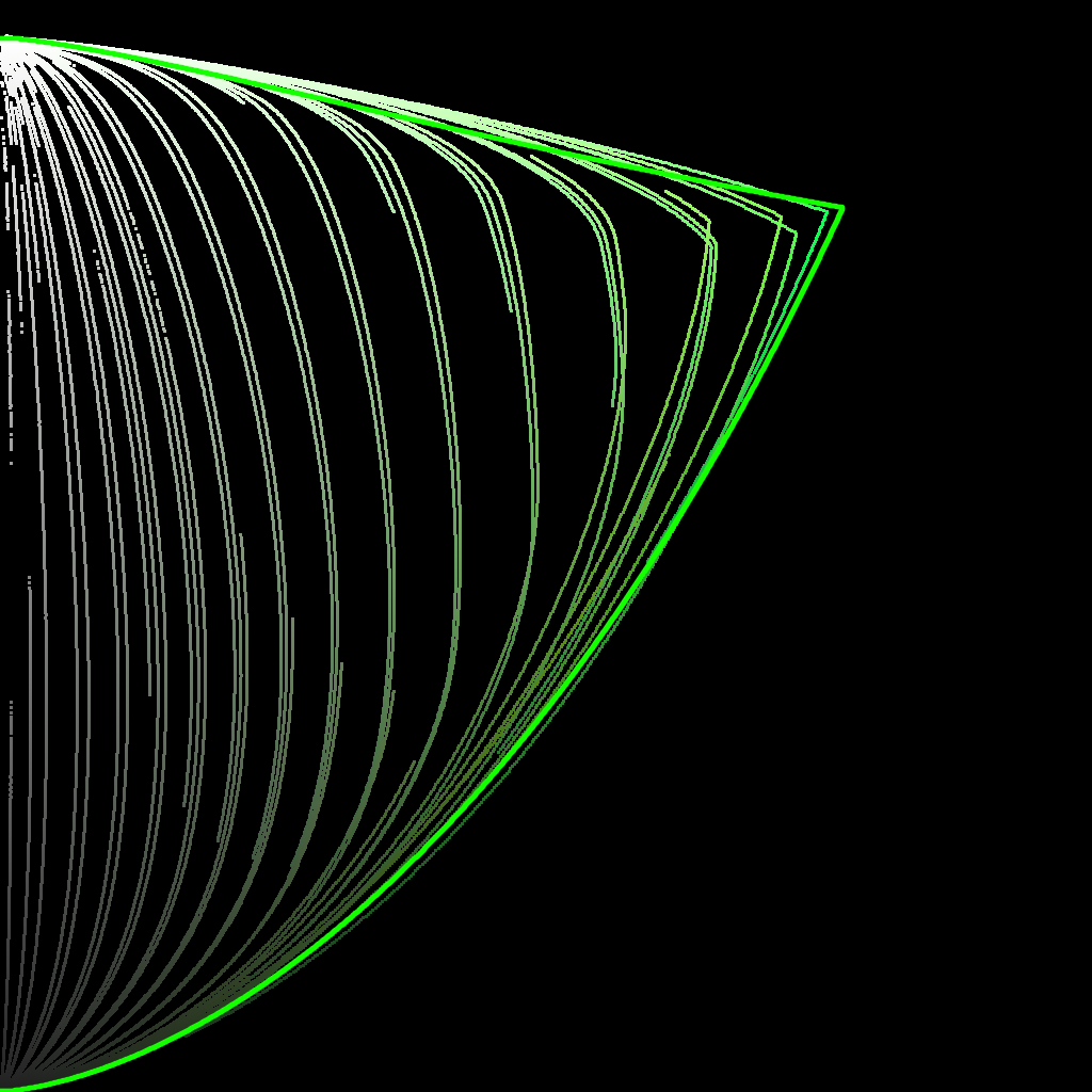
Started working up some tooling to visualise the compression vectors better.
In this first visualisation, we see a 0 → 360 h sweep.
Red is post tonemapped JMh
Green is post chromaCompression JMh
Blue is post gamut compressor JMh
Most of the sweep looks good, but it does seem like the chromaCompression around green is pre-compressing the gamut to inside the target gamut, leaving green values on the table.
This graphic uses a fixed h of 140.1 (max green in 709) whilst ramping chromeCompression from 0 → 1
1 Like
That’s nice. I’m not sure what the issue with the green is, though. The chroma compression is pulling all colors into gamut because if we don’t the interior of the gamut isn’t smooth. That’s the main reason for doing that step. Gamut mapper can’t do that. It does pull highly saturated colors less than less saturated colors, but everything is being compressed.
It has two steps. 1. path-to-white/path-to-black which is global hue-independent compression. All colors are compressed the same amount. 2. hue-dependent compression of different levels of colorfulness. Less saturated colors are compressed more than highly saturated colors. Gamut boundary is not considered. Now that it’s possible to get the boundary efficiently (since v29), it perhaps could be considered - somehow.
EDIT: did you use v28 or v29? My plots below are v29.
Here’s example of green with chroma compress set to 0 and 1 (step 2 still happens with it set to 0, but step 1 doesn’t), with gamut mapping:
chroma compress 0:
chroma compress 1:
(ignore the discontinuities in the lines. The input is just HSV hue sweep.)
1 Like
Is the solid green line the actual boundary? Does that mean we can’t quite hit the green primary? Or at least that we need an M value >100 to do so?
Those images are just for illustrative purposes for what happens in the interior of the gamut, they can’t be used to judge the exact limits. The input is not perceptual hue, it’s HSV ramp.
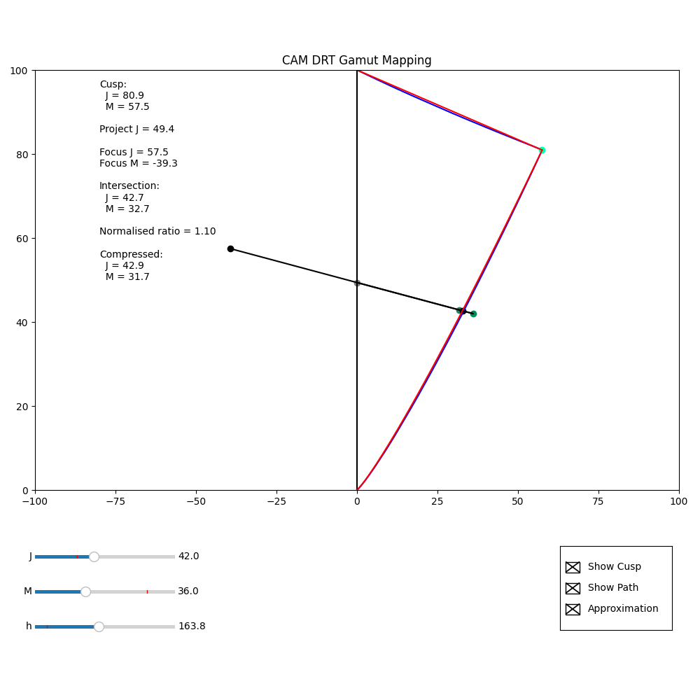
The Python in my Colab and repo, can now show the actual position of the focus point. This makes it clear that the focusM value is unaffected by the source M value, but does vary with source J.
The images below show (at least for this example) by displaying the focus point for a source – JM = (37.0, 62.0) – and then the focus point derived from the compressed values from that source – JM = (42.0, 36.0) – that although the focus point differs, the compression direction is not that different.
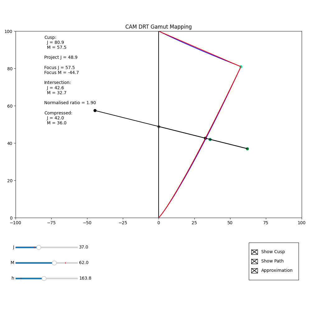
I was wondering if it might be possible to modify the calculation for the focus point, so it incorporated source M in the calculation, such that the focus point for a JM value after compression was the same as that for the value before compression. If this were the case, inversion would be simple.
But this is just me thinking aloud. I don’t know if it would even be possible.
(I do realise that I may just be saying “If the compression were trivially invertible, then it would be trivially invertible”!)
3 Likes
Hi,
I downloaded the CAM_DRT_v029 config during the last meeting and played around the the red_star image again together with an exposure node.
Plus I compared the output to a simple EOTF.
I figured I should have used the P3-config for my iMac when doing a screen-recording?
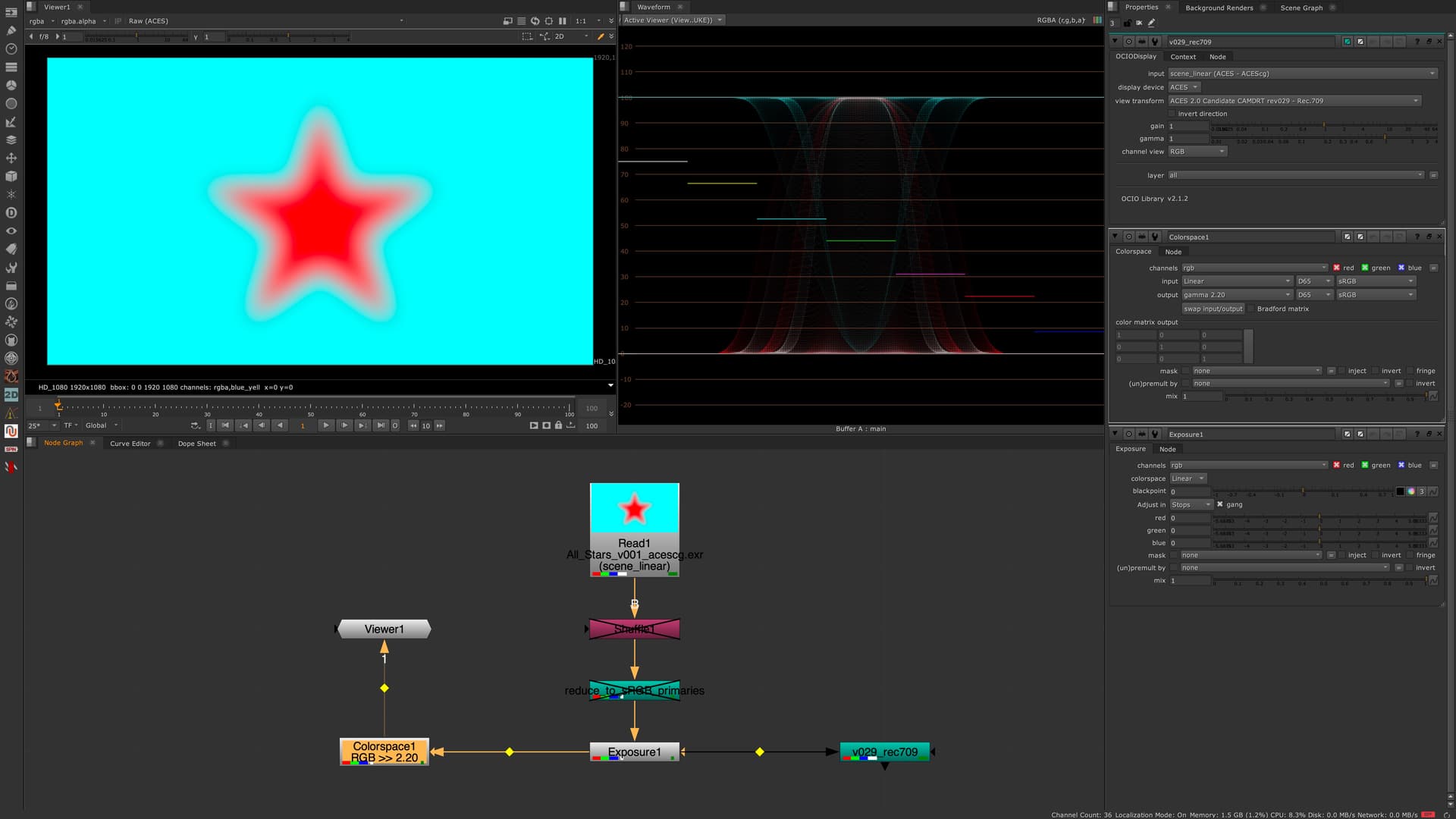
—> linear_sRGB 0-1 values with gamma 2.2
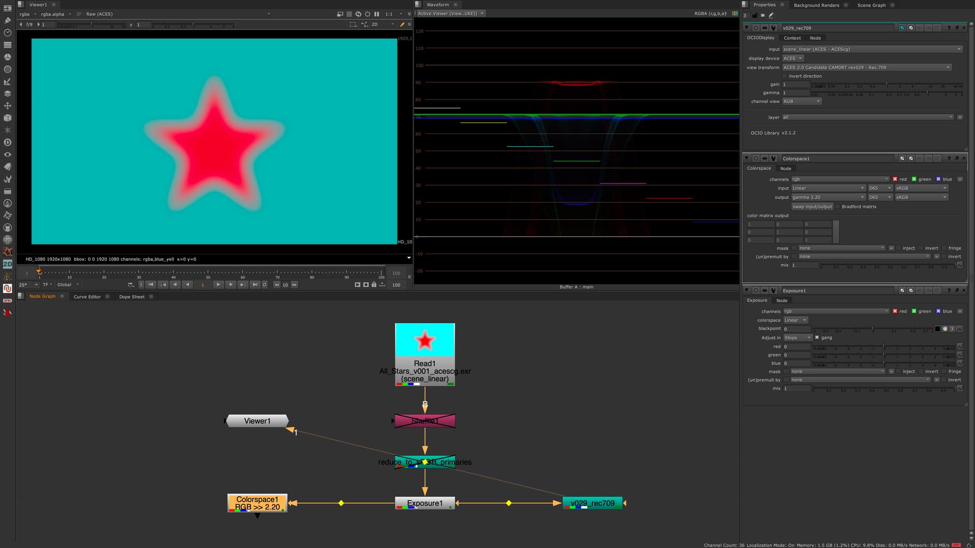
—> ACESCG 0-1 values over CAM DRT v029 for Rec.709
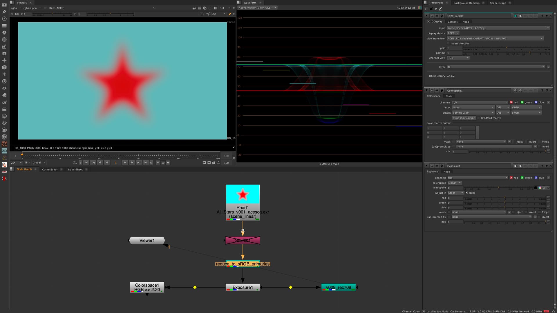
—> linear-sRGB 0-1 values in ACESCG over CAM DRT v029 for Rec.709
I wonder about the dip in the center of the red star in the waveform.
The displayed values are getting lower in the center of the star.
I could imagine it’s complicated to map the ACEScg red to the display, but a sRGB red?
To illustrate this better, I made a screen recording from within Nuke and a Histogram. I do not understand what is happening, but it looks strange to me that the red channel moves so different from the green and blue channel. The link to the video is here: HiDrive
1 Like
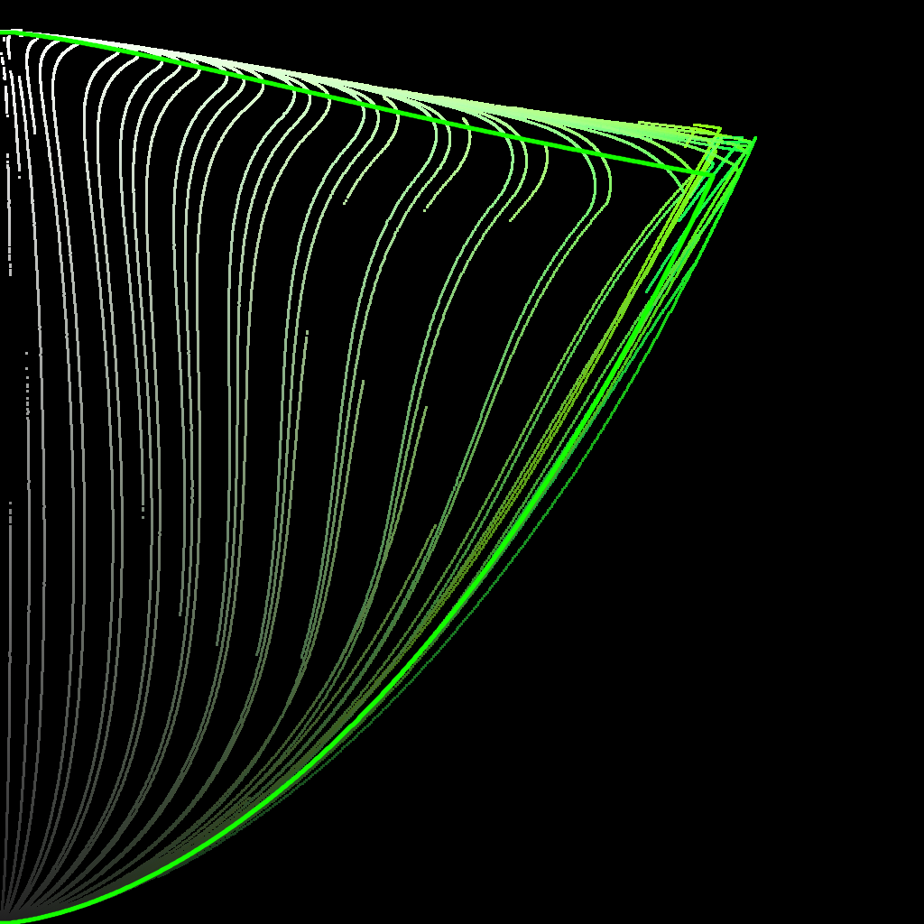
Following on from my previous comment about making the compression vector the same for any point along the line, I wondered if it might be possible to calculate the vector not from the J value of the pixel, but rather work backwards and calculate the vector from the J intersect value, and solve for what J intersect passes through the (M, J) coordinates of the current pixel.
This Desmos graph I hope illustrates the point.
I have not managed to work out the maths for solving for the right J intersect (or even if it is possible). My gut feeling is that it could possibly be rearranged to a quadratic equation, so the solution is given by the quadratic formula.
An iterative solve might be a temporary way to see if this idea is even worth pursuing. Maybe an inverted vector calculation like this will not give an appealing image.
And of course, as has been discussed, there is the trade-off between adding complexity to the forward transform and the possible benefit of an exact inverse.
I think I have found the solve.
Try this Desmos Plot, and if you drag the JM point along the line of the vector, you should see that the direction of the vector does not change.
My only concern is that there is not a solution that makes the vector go flat for J values of 0 and 100 if M is above a certain threshold. But hopefully the path to white and path to black should ensure this does not happen.
Updated, better annotated version for those who are interested, including “showing my working” for the quadratic solve.
3 Likes
Opened a new pull request for @alexfry for CAM DRT v030, also available from my fork.
It brings the new gamut mapper. The rendering of out of gamut colors changes quite a bit. Here’s my observations testing it, compared to v29:
- Highly saturated blue, green and cyan render darker
- Overall dark out of gamut colors render darker
- Looses a bit of saturation in blues/reds at higher exposures
I think this is a good starting point for further improvements now that the mapper itself no longer require iteration in forward or inverse direction.
2 Likes
I believe it’s the gamut mapper that’s pulling the red in gamut and mapping it also darker. sRGB red would be pulled in gamut a bit too.
I quickly tested exposure ramps with all the stars with v30, and the rendering has changed a bit. I like it better now, interesting to hear how you see them.
1 Like
@priikone Ive merged your PR
There is now a v31 in there too, which is your v30 with the addition six axis control over the gamut compression parameters.
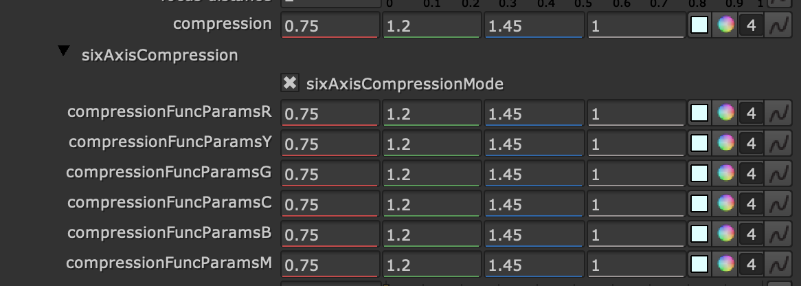
I think this should make it easier to tune the agressiveness of the compression along the yellow border, with the intention of helping the inverse.
1 Like
I started experimenting with hue-dependent gamut compression as well by using the same hue-dependent curve as what chroma compression uses (with different scaling). They both do the same thing so in principal the same curve should work for both. My initial findings were that it’s easy to improve the compression of yellow and orange, but not red. If red compression was reduced much from the current one, it produced ugly hue skews. Reducing compression comes at the cost of more clipping in the forward direction.
I also think the gamut mapper should have proper hue-dependent lightness mapping as well. The midToCusp blend worked better with the previous mapper than it does with the new one and that’s the only control we have for that.
1 Like
@alexfry a quick note, I noticed the v31 chroma compression slider is not in the default position (1.0). For baking the LUTs same way as before it should be set to 1.0.
1 Like
Derp, yeah I was swizzling that whilst looking at the inverse. Will update before I bake anything.
(edit: repo updated)
1 Like
Nick,
Taking a look at DRT_v30_709.dctl
Got working after fixing 2 errors and 1 warning.
Warning fixed in line 854 change 0.1 to 0.1f
Similar naming errors fixed by dropping the s from degrees and radians in lines:
548, 550, 555, 557, 744, 822, 940
Hope this saves a few moments for those running at this point.
Thanks and looking forward to more as it comes.
2 Likes
Regarding the white point discussion last week:
I always think of the white point journey like this:
- Scene White Point →
- Scene-Referred Encoding White Point / Mastering White Point →
- Encoding White Point
You see, I conceptually treat the scene-referred encoding white point and mastering white point as the same. But let’s start from the beginning.
Scene White Point
The scene white-point is the location the observer in the scene is adapted to. In our case, this is the white point you balance your camera.
We leave the balancing algorithm to the camera manufacturer typically (but not always).
So we can assume that a spectrally unselective object in the scene will land on R=G=B thanks to the camera’s white balance. And we can also assume that colours are falling roughly into place based on a given scene-referred encoding white point / mastering white point.
Scene-Referred Encoding White Point / Mastering White Point
The following white point I like to define in a backward direction. The mastering white point is the white point of your mastering colour space. Your mastering colour space describes the actual capabilities of your mastering displays. It encompasses all colours your mastering display can show. Typically the mastering colour space is something like
- Rec.1886/709 up to 100 nits for Video
- P3* up to 48 nits for theatrical (leaving HDR cinema out of this discussion)
- P3* above 600 nits for HDR TV
The mastering colour space can easily accommodate different white points by scaling its RGB primaries differently. For theatrical, we can have P3D55, P3D60, P3D65 etc… So I can dial in the mastering white point on my mastering display to my liking; this is why sometimes it is called Creative White Point.
It makes little sense to me to have a scene-referred white point which is different to the mastering white point, for several reasons:
Suppose a motion graphics artist creates a grey constant in a motion-graphic package by typing (r=g=b=a number) or a colourist fully desaturates an image until every pixel is (r=g=b=a number). In that case, the white point she sees is intuitively the white point of the data she works with. She does not care if we label the encoding D60 and the DRT D65sim. What counts is the mastering white point.
You could argue that the IDT target defines the scene-referred encoding white point. But the IDT optimisation assumes that the observer also sees the scene-referred white point; hence it should be equal to the mastering white point. Otherwise, the IDTs are not ideal.
Encoding White Point
That is the white point of the encoding colour space.
Sometimes the encoding white point is equal to the mastering white point; sometimes, it is not. You must NEVER put data in the encoding colour space outside the mastering colour space. Otherwise, you would produce colours the creatives have never seen and approved.
Very often, the encoding colour space is much larger than the mastering colour space (think of XYZ), but this is just because we are lazy in defining encoding colour spaces, so we always define the biggest one we can think of and move the actual challenges to someone else (who is typically not present in those meetings).
Recap
So I think (from a practical point of view) the mastering white point backpropagates the white point into the scene encoding, and the DRT should keep r=g=b on r=g=b.
You could argue that if that is the case, you must redo all the IDT matrices when you change the mastering white point. Yes, that is correct. We tried it with a few cameras where we knew the spectral sensitivities, but it is not worth the hassle for the amount of white point shifts we usually do.
Here is a video explaining some of that:

I hope this helps
Daniele
11 Likes