Sorry, I was not so serious in that moment). I only noticed that visual detail: the visual artefacts of clipped color data are same on initial image and transformed.
(and sorry for out of gamut colors was called “overexposed”)
Do not be “sorry”! It’s an absolutely critical definition that is ill-defined currently.
What is “overexposure” relative to a radiometrically open domain “scene”?
What is the sound of one hand clapping?
![]()
Apologies for the 1 month delay in any update. I have started a new job so my infinite free time has been significantly reduced which means progress is slower.
I have continued to work on my chromaticity preserving display rendering transform project as “color pragmatist by night”, and have made some progress which I will share.
I am still continuing under my initial assumption that this would be a neutral simple robust invertible display rendering transform which would not look great out of the box, but would do a good job at being information preserving and unbiased, and that it would be accompanied by an upstream LMT which would do the heavy lifting of crafting a pleasing image according to subjective aesthetic considerations.
I’m going to put this disclaimer in bold.
This project is highly experimental, under active development, subject to change without notice, and should not be used for production image creation. USE AT YOUR OWN RISK.
I have started a github repository here and written up some initial rough documentation here.
A few words about where I’m at. I am pretty sure that there is a much simpler version of this model hiding somewhere in the long labored hours of this monkey at a typewriter here, but I have yet to get there. So for the moment, this is not as simple and elegant as I would like. However I do think the image is getting to a place that is at least in the ballpark of looking marginally acceptable.
More to come…
7 Likes
There’s one thing that is currently not implemented correctly in the OpenDisplayTransform and I was wondering if any of you smart folks might be able to help me out. Maybe @sdyer if you have time?
It is regarding the HDR outputs. I admit I have a limited knowledge in this domain, and could probably use a little more reading and learning on the topic.
For the HDR outputs I have the implemented the PQ and HLG inverse EOTFs (basically copying what was done for the ACES Output Transform). However I’m not entirely clear on what needs to happen in the tonescale when changing the output to a higher nit-range display device. I know the mid-grey point might need to be shifted, and I know the luminance range mapped to the log domain might need to change, and there might be an overall exposure adjustment needed. But my knowledge here is a bit fuzzy.
Can any expert in this domain explain it like I’m five?
Thanks in advance!
As you have probably seen from the CTL, the HLG Output Transform is just the 1000 nit PQ Output Transform, followed by the PQ EOTF then the HLG inverse EOTF (with L_W = 1000) thus creating an identical image on a 1000 nit PQ and 1000 nit HLG display.
While obviously everything is up for debate, the current HDR ODTs all map mid grey to the same level – 15 nits. You can see clearly what changes if you run a linear ramp in ACEScct through the various HDR Output transforms, and look at the results on a waveform. The mid grey point stays at 15 nits (10-bit PQ CV 340) and everything below that barely shifts between the 1000 nit and 4000 nit PQ OTs. It is really only the roll-off above mid grey that changes.
1 Like
Last month I stumbled across something interesting which I will share here.
I was re-reading the paper A 3D-Polar Coordinate Colour Representation Suitable for Image Analysis - Hanburry / Serra 2002 for the 4th or 5th time, trying to wrap my head around the various forms of HSV HSI HSL and how they are constructed. I was trying to see if it were possible to construct a cylindrical HSV space defined with V in terms of max(r,g,b) instead of (r+g+b)/3.
As most of you probably already know, Chroma can be constructed as max(r,g,b) - min(r,g,b), and S in HSV is defined as (max(r,g,b) - min(r,g,b))/max(r,g,b). At the time I was also experimenting and testing as many norms as possible to better understand the pros and cons of each. In that paper there is a proof that Chroma is a semi-norm. So I wondered if I could use something like that as a norm for constructing RGB Ratios.
Max(r,g,b) works well as a norm. It’s arguably the most robust. Using Min(r,g,b) as a norm is just weird. It results in RGB Ratios that are entirely negative and … giant. Not useful. So then I thought, “Hey what if we go somewhere between the two?” So I chucked down a dissolve node and lerped between the two. The results were super interesting.
vec3 rgb = INPUT_RGB
float norm = max(rgb.x, rgb.y, rgb.z)*0.5 + min(rgb.x, rgb.y, rgb.z)*0.5
vec 3 irgb_rats = (norm - rgb) / norm
RGB Ratios generated with the above method look pretty similar to those generated using the max(r,g,b) norm, except they had less secondaries mixed in. With “traditional” Inverse RGB Ratios, the red green and blue channels represent the secondaries: cyan magenta and yellow. But the secondaries are “wide” in that they incorporate all colors, just centered on the secondaries. In my many experiments it has been useful to have access to individual hue directions. Make reds darker, reduce luminance of blue, bias hue direction of red towards yellow, etc, etc. Ideally you would want a model that did the right stuff without resorting to per-hue adjustments, but per-hue adjustments are still necessary at a certain point.
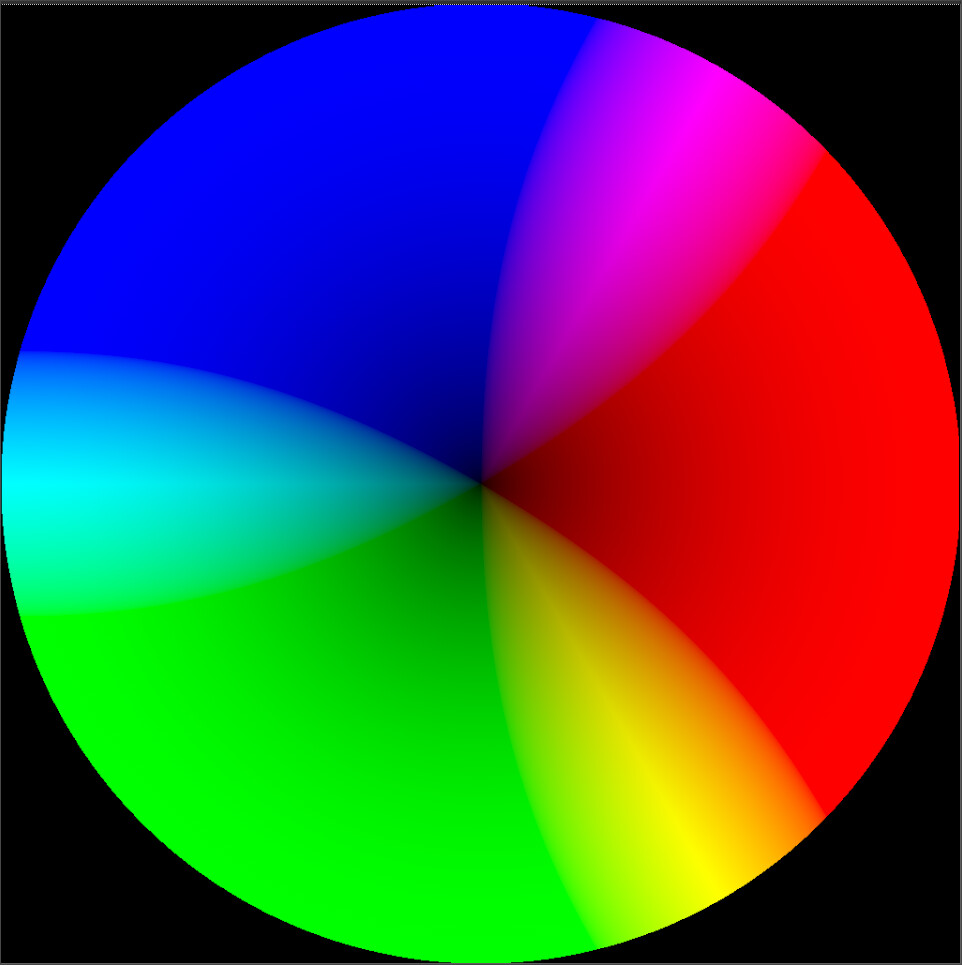
So to show what this looks like here are a couple screenshots of a standard colorwheel.
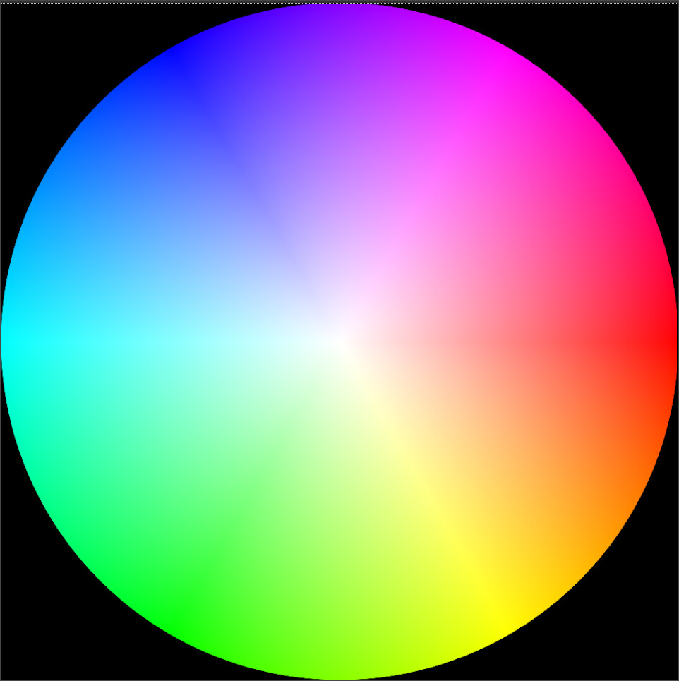
“Traditional” inverse RGB Ratios look like this.
Notice how the “cyan” (red channel) incorporates all colors from input yellow around to input magenta, centered on Cyan. This is what I mean by “wide”.

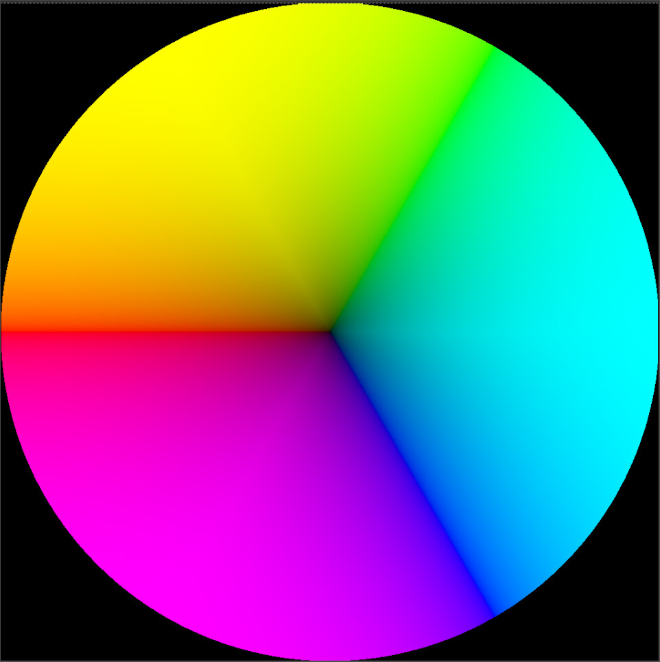
Using the “halfway between min and max rgb” norm, the inverse rgb ratios look like this instead:
Complements are positive, primaries are negative. It’s like a 3-component opponent colorspace which represents all corners of the RGB cube hexagon.
The red channel representing cyan, looks like this:
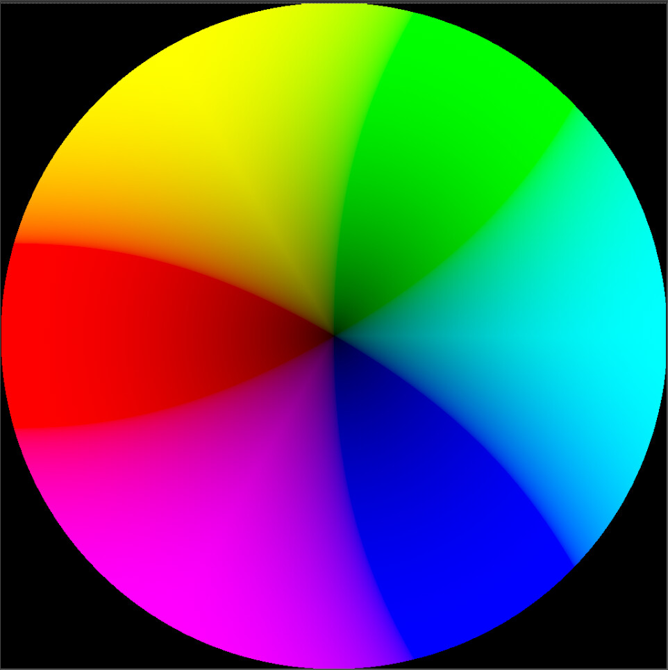
And if you multiply the ratios by -1 you get the primaries:
Anyway, just something interesting I stumbled upon in my experimentation, which I thought might be useful.
3 Likes
It is a good model I came across last year during the gamut mapping ramblings (and poked at a bit), I made an implementation in Colab back then and there is a PR pending to get it in Colour here:PR: Implement support for "IHLS" colourspace. by amulyagupta1278 · Pull Request #614 · colour-science/colour · GitHub
Hey folks,
Appreciate the conversation here. I wanted to share something I am observed in regards to color/hue shifts when sRGB primaries are brought into ACEScg color space. In this image the color swatches on top are from a linear EXR in sRGB primaries. Below are the same in ACES on bottom (read in with the scene-linear Rec.709-sRGB to ACEScg color space).
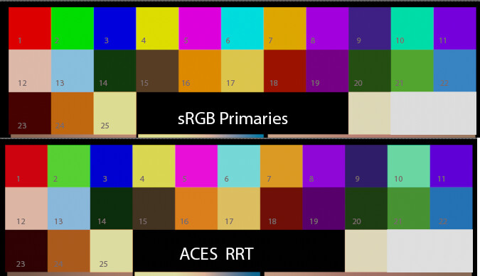
Most notable to my eyes are swatches 4, 6, 10, 11, 18, 21.
de/Saturation
#4 is desaturation of yellow. This was listed in the dropbox paper Output Transforms Architecture.
#6 desaturation of cyan
#10 desaturation of teal
#22 saturation of blue.
Darkening
#18 (also 14 & 23) darkening (luminance). Paper says under tone scale design requirement “slightly lower default contrast” I think this would likely solve this.
Hue shifts
#2 hue shift green to yellow
#10 hue shift cyan to green (plus desat)
#11 hue shift violet to blue (plus desat)
#21 hue shift green to blue
The paper mentioned hue shifts of primaries with increased exposure, but I did not see mention of hue shifts going from sRGB primaries to ACES. Is this something on the radar for the new Output Transform?
Let me say that I am coming at this from the perspective of an artist, and that I’m offering these naieve observations in no way to make conclusions, but rather in the hopes that bigger brains than me might have some insights into what’s going on. It’s been pretty awe inspiring lurking here and listening. They say if you are the brightest guy in the room, you’re in the wrong room. I think I’m in the right room 
Yes, it is part of the discussions pertaining to a chromaticity-preserving rendering transform. Keep in mind though that as desaturation occurs and because the sRGB and ACEScg basis are different, it is expected to get different hues.
Cheers,
Thomas
@Derek #18 (and #1 too if you look carefully) is the red modifier of the RRT. If I’m not mistaken, it’s in there because Rec.2020 red was deemed too red. Moving this modifier to a standard LMT is one of the big requests of the RAE paper.
Jean-Michel
1 Like
Hi @ChrisBrejon and everyone who has not seen enough the RED XMAS clip  yet.
yet.
Here is my take on the “Red XMas” footage. I ran the R3D file though Resolve 17 (ACES) and FCPX (HDR-WideGamut project). As the bulbs are clipped in the sensor I am never able to “see” them as a red light source, I can only see all the objects around that receive the red light from the bulbs. I had a a simple 3D scene for a HDR test from last year and turned the “lights” red. In this way I can play with the intensity of the red bulbs without any clipping (only in LogC encoding for in later tests)
If you view this page on an iPhone (11 or higher) in Safari you can see the following links in HDR (EDR).
Without a proper HDR monitor setup I cannot judge a HDR project on my iMac (EDR) screen in Resolve. FCPX works far better here, that’s why I do the majority of my HDR tests with FCPX and review the results on my iPhone screen (and soon on the new iPad Pro )
First I took the R3D file and passed it though Resolve 17 (ACES)
https://vimeo.com/544454696 (check the work steps in the subtitles)
Next I passed it though FCPX that allows via the RED SDK to read the file as RedWideGamut or Rec.2020.
I also converted the R3D in Nuke to Alexa LogC, because I found FCPX works best with Alexa encoded footage when working in a HDR WideGamut project, especially if material is rendered in ACEScg.
ACES is not supported in FCPX.
https://vimeo.com/544466973 (check the work steps in the subtitles)
The next clip in SDR. I rendered some red bulbs in Blender linear-sRGB and compared them with the standard sRGB (left) and FILMIC view transform (right). The red emission is in the first and last image the same, only the strength of the HDRI is different. The “cyan” patch on the colorchecker sticks out a lot in this strong monochromatic light setup.
https://vimeo.com/547176470 (check the work steps in the subtitles)
Blender FILMIC has no HDR view transform to my knowledge. So I exported the linear sRGB renderings as LogC ProRes files and imported them into FCPX. This time you see on the left the ungraded result and on the right a more please grading attempt with the color correction tools from FCPX. The next clip is again in HDR.
https://vimeo.com/547185384 (check the work steps in the subtitles)
The next HDR clip is showing the R3D footage and my rendering side by side.
I had to grade down the R3D bulbs to around 400 Nits to get a pleasing result, but the 3D render looks also fine when I push the bulbs up to the 1.000 Nits limit (FCPX has a nit limiter that can be set to different maximum levels. I am always using maximum 1.000 Nits).
https://vimeo.com/547202998 (check the work steps in the subtitles)
And the last clip is again from Resolve 17 in ACES. The renderings full screen.
https://vimeo.com/547213466 (check the work steps in the subtitles)
Its a pity I cannot judge any HDR output directly on the Resolve UI. I filed this as a bug, I hope this will get fixed one day. FCPX works very good with HDR material without an external monitor setup. FCPX is working with a linear Rec.2020 working colorspace as far as I could find out. I don’t think it has any gamut mapping function. But the Color Wheels are very intuitive to control and I find it a very good tool to learn about HDR grading.
I check my results also from time to time on a LG C8 in an office and must say, the general impression of the HDR clips feels quite similar between the TV screen and the iPhone display.
Best
Daniel
3 Likes
Just a quick note to say I’ve pushed a new release of my OpenDRT project.
I finally got to a point where I felt like there was enough stuff sufficiently figured out to share another version. I’ll be working on a DCTL port tomorrow so that there’s a less arcane reference implementation compared to Nuke expression nodes.
4 Likes
Hi Jed,
here is just a quick followup test of the RED X-MAS footage with your new DRT.
I used the preset Rec.2020 1.000 Nits. Then I exported a ProRes444 out of Nuke and did a colorspace override in FCPX to Rec.2020 PQ and re-exported the ProRes again without any other operation. But I had to apply the HDR tools and set a PQ limit, otherwise the exported file is not recognized by Vimeo & YouTube properly.
Is there a way to write the right color tags into the ProRes file directly in Nuke?
The file looks good on the new iPad Pro ![]() (HEVC 10-Bit) through a .m4v file that I compressed out of the ProRes 444 with Compressor.
(HEVC 10-Bit) through a .m4v file that I compressed out of the ProRes 444 with Compressor.
For the Vimeo upload I used the ProRes444 file directly.

(not shown in HDR/EDR on the new iPadPro in Safari, but in the Vimeo App)

Greetings
Daniel
2 Likes
There is now a first version of a Resolve DCTL implementation as well. Presets are not there yet, but it’s functional in both forward and inverse directions. There may be bugs as it is a first pass, but it should be solid enough to play around with.
1 Like
Hi @jedsmith ,
I felt I needed to reply to my own posts, because although I managed to get the Red XMas footage and my renderings in the last post to platforms in SDR & HDR, I still did not have an answer to my own question:
Why is a red bulb displayed „white“ instead of „red“ in the R3D file? I know it’s a red bulb and it shines only red light to the surrounding areas.
I would like to see and show that somehow. And I used your new version of the OpenDRT at the end again and compared it to the ACES ODT output.
One part I can answer to myself easily:
In the RED footage the bulbs are always clipped to „white“, because the camera sensor was „saturated“.
The information of the bright red light brought into the „scene“ was lost on input.
That’s why I took a step back and setup some 3D renderings where I have more more control.
I „filmed“ my own „RED“ bulbs scene.
With this step I skipped the IDT part of the R3D footage and started directly in the „scene“. And as everything is generated in the scene, I can only get „clipped“ values on output.
Over the last weeks I rendered different tests and I presented some of them in my previous post. The renderings look similar to the R3D footage in a way as I replicated a night time scene and red bulbs that shine only red light onto the surrounding objects.
But an even more simple rendering made me „trip over" my own question.
I made a 3D scene which is as simple as possible:
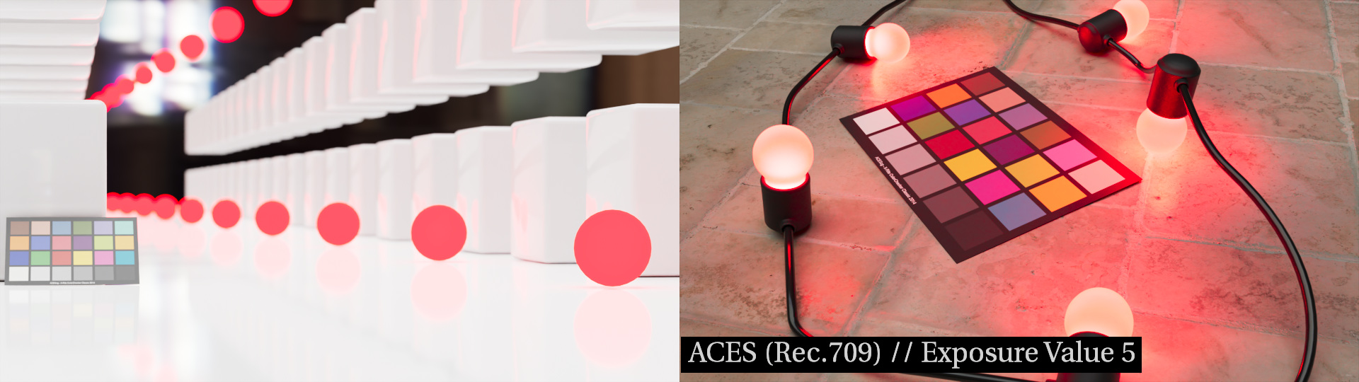
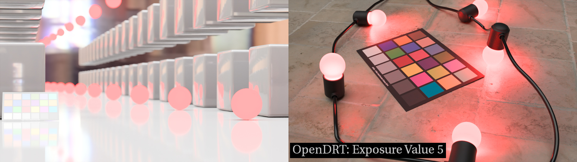
A scene in linear-sRGB and a sRGB view transform (inv. EOTF); a random dark environment HDRI that I created myself; a scene with red spheres with an emission shader of 0.5/0.0/0.0, some objects to receive the red light; and a color-chart.
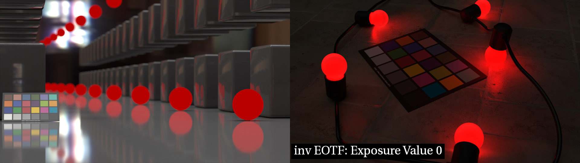
My question still is, what happens to the red emissive objects if I raise the overall exposure of the scene. Based on the initial rendering I did an exposure sweep from -4 EV to +5 EV stops and rendered the results into a file.
I am only focusing on the left side of the split screen. Of course I expect that my scene gets overexposed in an ugly way.
At the highest exposure I basically see red and white on the display.
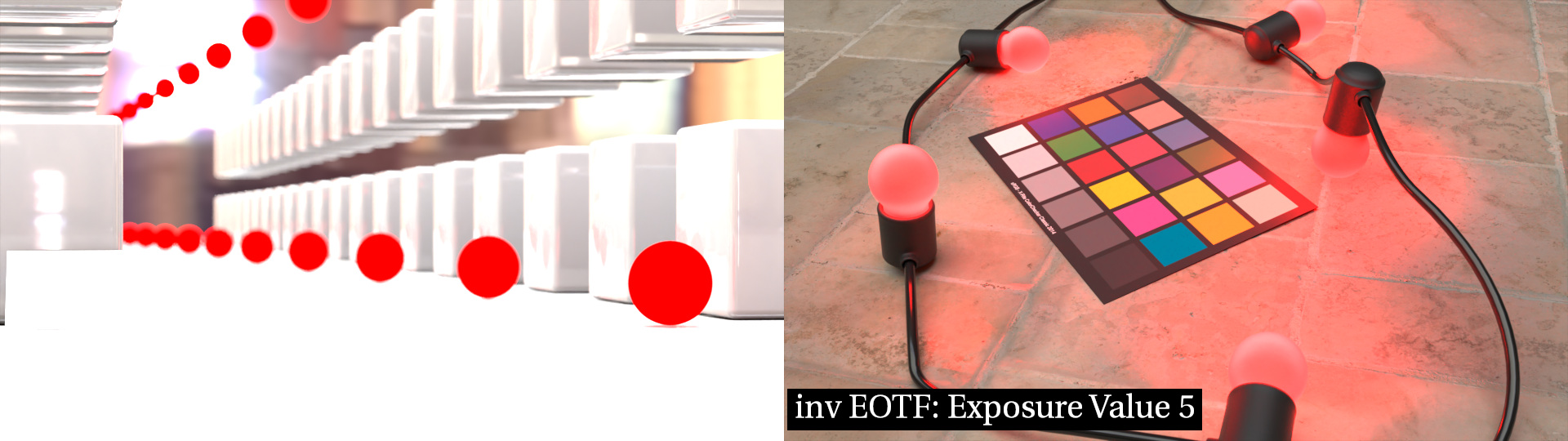
The scene values read around 15 on the red emissive spheres and around 3.3 below on the floor.
Now I see what I wanted to see.
Very bright red emissive objects that in this case are around 5 times brighter than the surrounding floor.
But now the floor looks „brighter“ than the red spheres. Between EV +1 and +3 the image „flips“ somehow over.
Although everything gets brighter, the actual red emitting objects start to appear darker. This feels wrong. They should also get brighter.
I know that the display cannot emit more red light than the display maximum, so it has to get struck at full red emission.
I am happy that I could render this result, but I am not happy with the „look“ of the result.
When I now go back to this clip, I am somehow more happy with „white“ bulbs, because they feel brighter.
To finish up this post, I rendered the same images though ACES (Rec.709) - I use ACES in my daily work - and though the latest OpenDRT from @jedsmith compare the results further:
Here I use a properly setup scene in ACEScg.
Here I use the linear_sRGB scene.
Both renderings desaturate the red emissive spheres, but still they never feel like being bright enough.
If someone wants to have a look at the EXR files, I can upload them of to the dropbox or somewhere else of course.
2 Likes
@TooDee I think it would interesting if you ran these tests with a non-pure red light too, say (1, 0.05, 0.05). In theory, as exposure is raised on a pure saturation (1,0,0) it would never go to white, but the “non-pure” red would as the 0.05 for green and blue would eventually hit 1 with enough exposure.
Hi @Derek ,
why do you think it’s interesting to do this test if you know already the outcome of it?
The math is rather simple and yes you would eventually end up with “white” on the display.
But I don’t define in Blender my shader value on a display value, I define it as a “light source” or an emissive object in the “scene”. That is something completely different.
Yes, I am referring to the light/emissive color in scene-linear, not to a display value.
What would be interesting is to see is how it behaves differently through a chomatically-preserving output transform than it does through a per-channel one. Since they handle the path to white differently, I don’t know the answer already ![]()
Hi @Derek,
are you familiar with Blender? I am happy to share the scene file. Then you can try it for yourself as I don’t know what kind of different tests you are thinking about.
But for sure you know the answer. Even with standard sRGB and the then not pure red emissive spheres, the image will blow out to white to display “white” eventually. With Blender/Filmic it happens in a different way. And in the the last two images of my post you see the results with the ACES ODT and the OpenDRT.