Aces 2.0 DRT Testing

Hello,
I’ve been somewhat following the development and candidate testing for the new Aces 2.0 DRT, but am currently out of the loop about the most current version and am wanting to do some personal tests. However, I am having trouble finding a download for the most recent version of the DRT – I think I found a .ctl for the correct version but don’t know how to transform images using a .ctl, so am looking for some help with that or some help finding a .dctl implementation for DaVinci or a Nuke implementation.

Thanks in advance for pointing me in the right direction!

For DCTL, all the ones with “rc1” in the name here should be the latest. Make sure that includes hellwig_lib_rc1.h.

For OCIO, I believe the ones called “rev060” here are the latest. But @alexfry would have to confirm that.

There is a full procedural implementation in OCIO v2.4.0 which was recently released, but that is not in any shipping apps yet, so can only be tested via e.g. the Python bindings, or command line tools.

And the rev60 Blink implementation for Nuke is here

1 Like

Thanks !

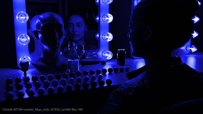
I did download v060 from Alex´s repo and checked one of my renders with a blue grade.

Basically, my setup is:

  • working space: linear-bt.709
  • blue is grade is a mult at (0,0,1) (a blue primary basically)
  • display space: rev060 - Rec.709 (ACES)

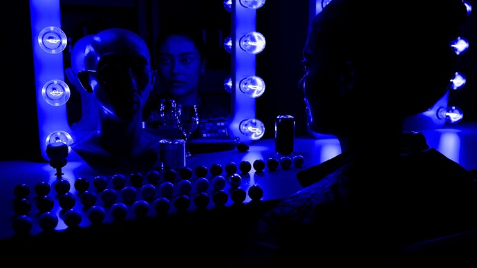
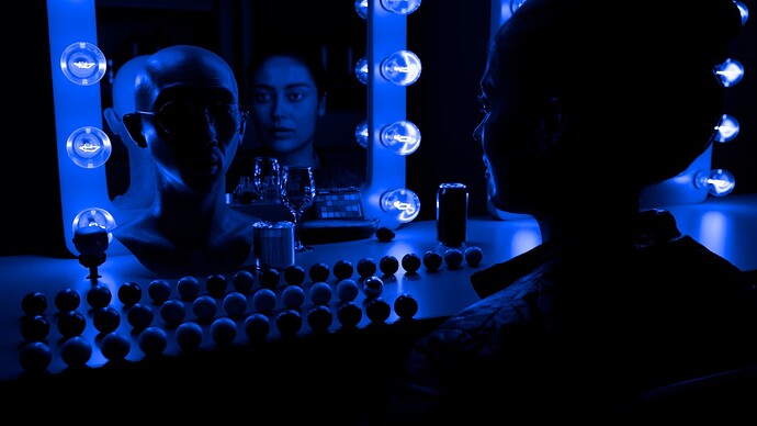
I see some weird sharp disruptions in the gradient. But weird thing is that I cannot remember seeing such artefacts in the meetings.

Is my setup wrong somehow ?

Chris

Can you share your rendering before “grading” it blue?

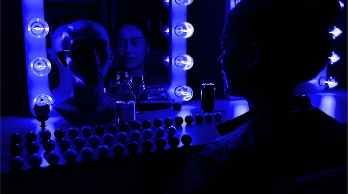
Yes, here it is.

Technically, there is only one mesh light in the scene representing the filaments.
So, when I put the blue grade, it would be the same as putting the light color to (0,0,1).

Thanks !

Sorry, I meant sharing the EXR file :slight_smile:, so that we can try the DRT ourselves.

Sorry, I misunderstood.

It is in the Dropbox

The exr has been encoded in ACES2065-1 but actually rendered in “linear-bt.709”. So your Nuke working space should be “linear-bt.709”.

Thanks for having a look !

2 Likes

Hi @ChrisBrejon ,
now I am a bit confused.

I understand you rendered this file with a working space linear-bt.709. So not ACEScg, therefore you never “lookdev” the image seeing it through any ACES view transform, right?

Then the EXR was saved as an AP-0 EXR, so a matrix was applied from linear-Rec.709 to AP-0, right?

To test out your file I use the OCIO config from @alexfry (rev060), read your file as AP-0 and view it through the ACES 2.0 view transform for Rec.709.

Why should I change my working space to linear-bt.709? It should by anyway ACEScg, right?
This is the step where I have trouble following you.

Visually I get in any way a different result than you have.
Please note that I use a MAC, so I am using the DisplayP3 limited OCIO config.

The visual difference between the DisplayP3 and regular Rec.709 view transform is basically not noticeable.

Best, Daniel

Hey,

at some point in the OT VWG (maybe like 2 years ago), I remember switching my CG tests to a “linear-bt.709” rendering space for the sake of simplicity.

This scene was indeed lookdev using TCAMv2 back in the day. But I do not think it matters for the point I am trying to make.

You may observe the same issue by:

  • having your working space set to ACEScg
  • setting the light to (0,0,1) in “linear-bt.709” (with a constant in Nuke for instance)

I think it is a valid choice to keep working/rendering in “linear-bt.709” but using the ACES 2.0 Output Transforms for display.

Here are more images:
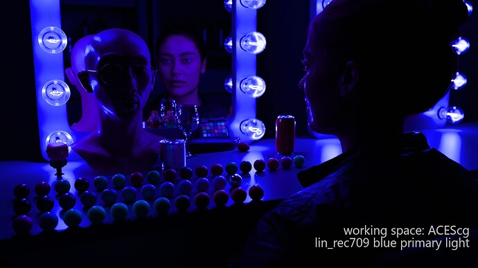
Working space is ACEScg but the light is a “linear-bt.709” blue primary:

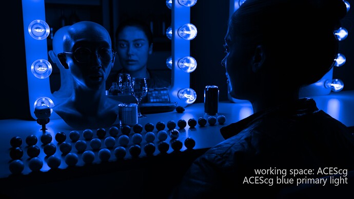
Working space is ACEScg but the light is an “ACEScg” blue primary:

The breakup is easy to reproduce with “lin-bt.709” ramp displayed with the ACES 2.0 Output Transforms:

Hope that clarifies things,
Chris

2 Likes

Hi,
I took a step back and started from the beginning:
Reading you initial EXR into Nuke as AP-0 in a linear.BT709 working space and then did the multiply operation actually in linear-BT.709 and saved out the new “blue only” EXR as a Lin-BT709 file.

This file is my new “blue” master. In this way I can avoid of doing the multiply operation in different working spaces.
I also created a linear-BT.709 ramp similar to yours.

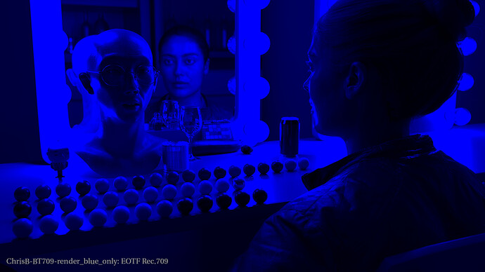
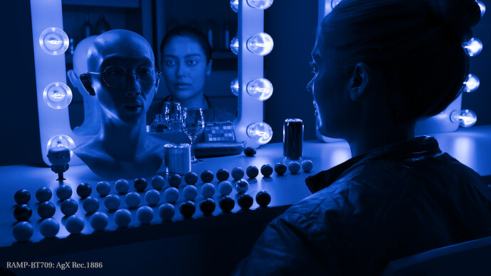
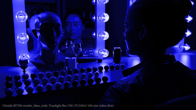
These two EXR files I passed though different OCIO configs and render out each a JPG (EOTF Rec.709, AgX Rec.1886, TCAM Rec.709 and ACES2_rev060 Rec.709) file.


What puzzles me the most - as far as I can see none of your images look identical to the ones I created.
Just by chance we should have done the same steps somewhere, right?

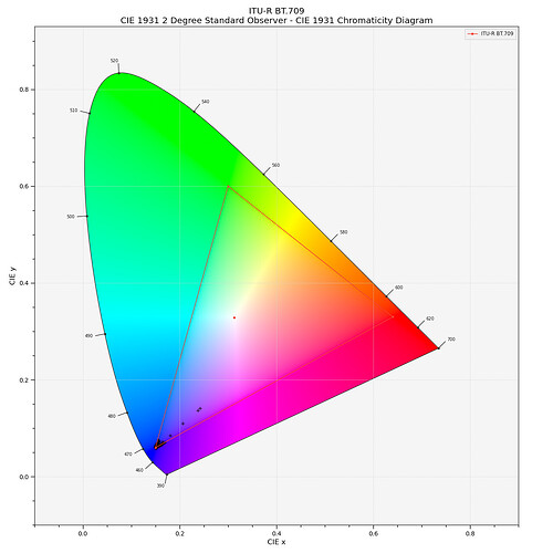
I wanted to plot the “blue” only EXR, but I always got an “empty” plot.

Then I tried to multiply with other values than zero for red and green and ended up at 0.0001/0.0001/1.0.

I guess when I multiply by zero, all the remaining plot points collapse on the blue primary, right?
That’s maybe why the plot seems to be “empty”?

Hello,
I did some testing based on all of this and it may be helpful-
I built an OCIO config based on the rev060 LUTs that Nick shared, and confirmed that it matched the Blinkscript implementation (as a note, in my config I’m using the BT.1886 rec.709 rev060 LUT but converting from BT.1886 to sRGB for my display) .

Using my rev060 config and Nuke, I tried to recreate Christophe’s results-
First, I worked as explicitly as possible where I knew for certain what colorspace the image was in at every step-
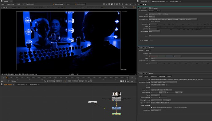
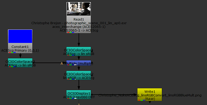
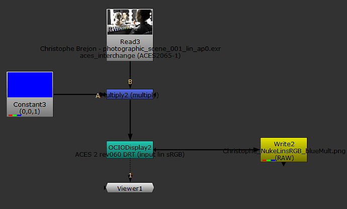
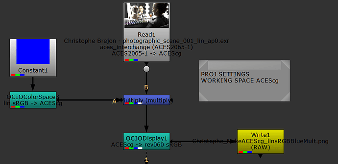
Christophe_NukeACEScg_linsRGBConvert_linsRGBBlueMult-NukeOCIO
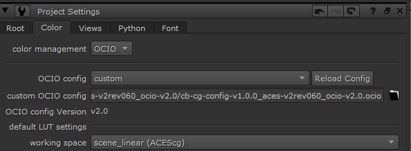
In my config, the scene_linear role is ACEScg, matching a “regular” ACES config.


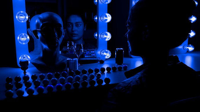
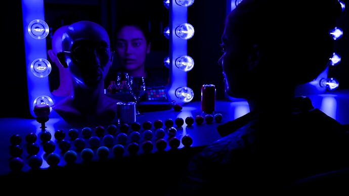
I read in the image as AP0 (thus transforming from AP0 to AP1), then matching Christophe’s desire to perform this operation in linear sRGB, I converted from ACEScg to linear sRGB. I created a primary blue image with a constant, but since my Nuke working space is ACEScg, I converted from ACEScg to Linear sRGB, and multiplied that linear sRGB blue primary (EDIT: Mistake here, this is the ACEScg primary in linear sRGB) with the linear sRGB image. I then converted back to ACEScg for the DRT, which resulted in this image, which does not have the artifacts that Christophe experienced-

I then did the exact same thing, except instead of multiplying by the linear sRGB blue primary, I multiplied by the ACEScg primary blue instead by bypassing the colorspace transform:

Which resulted in this image, which does have the artifacts Chris mentioned-

As I mentioned, I first wanted to do this test when my Nuke working space was set to ACEScg, because I have not experimented with changing the Nuke working space away from the scene_linear role, so I wanted to first perform testing in an environment when I knew exactly what was going on.

My final test was to actually change the Nuke working space in the settings, though:
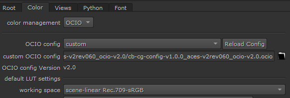
Christophe_NukeLinsRGB_blueMult-NukeOCIO

And then read in the image with the AP0 transform, multiply the image by 0,0,1, and then view the image under the DRT where the Display Transform is expecting a linear sRGB input rather than the scene_linear role ACEScg input.

This workflow resulted in an image matching the artifacts as well-

In both cases, multiplying by the “working space primary” with values of 0 in the red and green channel resulted in the artifacting, which frankly is not something I am surprised by. I’m a CG artist and have read Christophe’s CG cinematography book (Thank you for that resource Christophe, by the way), which is where I originally learned about avoiding pure primary values with zeroed out channels in lighting, which resulted in artifacts with ACES 1.3 and other color management workflows that this instance reminds me of.

In the first test that I did that did not result in these artifacts, I believe that I followed Christophe’s desired workflow (bringing the image into linear sRGB, multiplying by the linear sRGB blue primary, and viewing with the ACES 2 rev060 DRT), but I did it within the context of the ACEScg working space which prevented any 0 values in the multiplication.

Another factor that may be important here is just that – the working space in Nuke. My standard workflow with OCIO configs is to define my working space with the scene_linear role, and when you load a config into Nuke that is the colorspace chosen as the working space by default, and when you create OCIO nodes in Nuke the colorspace that role is set to is the default for many of the options. I am unsure that it is a good idea to change the working space away from this role in the project settings – firstly because defaults in nodes will not match your newly set working space, and secondly because I’m not sure how much of Nuke actually adapts to that working space change – for example, when using the Nuke viewport View Transform (in the top left of the view panel), if you are looking through only a single read node with a properly set IDT, the visual result in the viewport will change, which suggests to me that either the IDT transformation from encoded → working space or the view transform from working space → display is not properly reflecting the user change in the project settings. This introduces unknowns into the equation in multiple ways – since I’m not able to explicitly know what Nuke operations are properly reflecting this change, I would rather not change my working space there.

Hopefully some of this is helpful–
Conlen
1 Like

Thanks, I think your results confirm my findings.

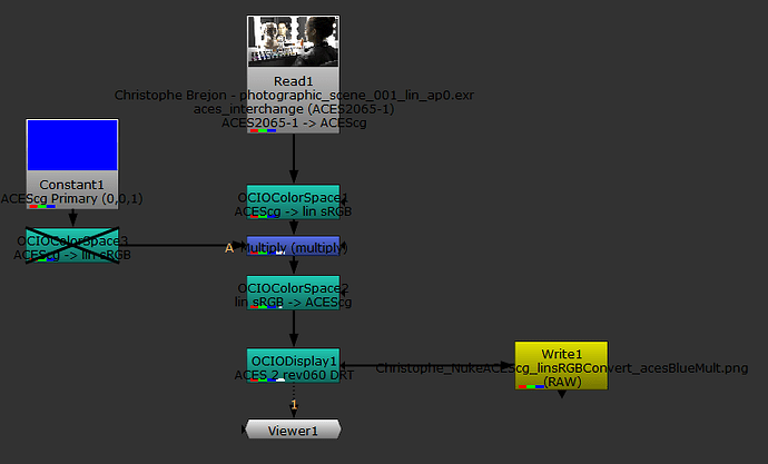
In this screenshot:

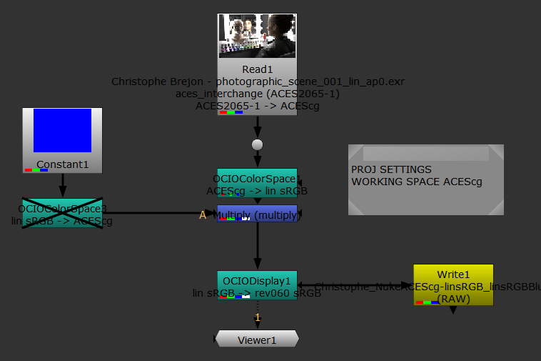
  • try to remove/disable the “OCIOColorSpace1” and “OCIOCOlorSpace2” (the ones right before and after the multiply)
  • Invert the transformation of “OCIOColorSpace3” (it should be from lin_sRGB → ACEScg)

Could you confirm you are seeing the artifacts with these changes ? That would be helpful.

I have seen similar artifacts when I work with wide gamuts but never in lin_sRGB. Hence my surprise.

Also, there might be an upside of having your working space set to “linear_sRGB” in Nuke. It is that some color nodes of Nuke have been designed with such primaries in mind (such as saturation I think).

Chris

Hi Chris,
Following those steps I produced this node tree:

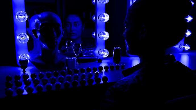
Taking the ap0 image into ap1, and multiplying the image (in an ap1 working space) with the linear sRGB blue primary results in the artifacting-

Conversely, with this node tree:


Taking the image from AP0 to AP1 and then to linear sRGB and multiplying by the linear sRGB blue primary and displaying the image with the DRT (expecting a linear sRGB input) does not seem to result in the artifacting:

To my understanding, this second node tree represents multiplying the image by the BT.709/sRGB primary blue while in linear sRGB, and does not have any artifacting.

However, I am now unsure as to why multiplying by the linear sRGB blue primary while in ACES is resulting in this artifacting, assuming that I am correctly setting everything up.

As having the nuke working space be in linear sRGB, I definitely agree that based on specific workflows this can be a valid or even correct choice – what I meant to demonstrate in my last message was that simply changing it in the Nuke UI seems to result in unexpected behavior, at least from what I was seeing. It seems like a better choice to specifically construct the OCIO config so that scene_linear is already linear sRGB, at least from what I found.

Conlen

i get the same result as @ChrisBrejon when doing the same thing in resolve using the RC1 dctl version of the DRT .

1 Like

In that specific scenario, you don´t see the artifact because the blue primary is ACES, not linear_sRGB. In Nuke, the constant will be expressed in the working space.

So that second example is not 100% accurate in my opinion. But I think we agree on the important part which is a linear_sRGB blue primary will create artifacts at a certain exposure.

Chris

Even with chromaticities matching the bt.709 blue primary, significant disruptions in gradients are observed as the signal crosses the blue corner of the display gamut cube.

Significant disruptions and non-smooth behavior occur in that region at lower purity, and it gets even worse at higher purities between bt.709 blue and AP1 blue primary chromaticities.

These issues have been pointed out before and were not addressed much. See @TooDee 's post here, Nick’s visualization here, @jpzambrano9 's post here, and @meleshkevich 's post here

I think it’s safe to say that ACES 2.0 prioritizes invertibility and “reaching all corners” more than having nice image appearance. Those two design goals are strongly opposing I would say.

The nuke script that generated the above plots if anyone wants to try for themselves:
photographic_scene_001_bt.709_plot.nk (357.7 KB)

4 Likes

You make a good point @jedsmith. But I would just expand on it to say that we sacrifice having a nice image appearance for every possible source image “out of the box”, in order to hit the corners and be invertible. You can of course use an LMT which “rounds off the corners”, and will therefore smooth out the appearance for extreme images such as the pure blue example.

Yes, and there are other “corner” cases also, like if you have values outside AP1, they would be clamped and may cause visible skews and/or discontinuity.

Thanks for your answers ! Thinking out loud here:

  • Should we provide such a LMT to the users, maybe even activate it by default in the CG config ?
  • I recall that one of the design requirements was to look good “out-of-the-box”, so maybe we should plan for that.

Chris

1 Like