Discrepancies using a “pseudo” ACES workflow in DaVinci Resolve via ACES Transform OFX Plugin

The latest versions of Davinci Resolve (from 15.2.2 but maybe since v15?) allow for creating a very powerful “pseudo” ACES workflow using DaVinci’s new ACES Transform OFX plugins. It also allows for using tools designed to work in Davinci YRGB colour Science inside a full fledged ACES workflow within DaVinci.

The scope of this post is not to dive deep into all the possibilities of both scenarios but to explore what I found to be a slight discrepancy on the rendering that DaVinci applies to an Alexa LogC image when you create a pseudo-ACES workflow using ACES Transform nodes (in YRGB colour science) as opposed to setting your Colour Science to ACES (ACEScct in my case) on the colour management preferences.

The pseudo ACES workflow was briefly described in a previous post:
https://community.acescentral.com/t/luts-that-emulate-the-aces-workflow/1334/11?u=theoribeiro

I’m no colour scientist, rather a curious cinematographer who is very interested in colour so forgive me if my tests are very empirical and the results not exactly conclusive.

I created three testing scenarios to see if the results were the same when processing both a 16bit Linear Grey Ramp and the classic ARRI Isabella.dpx test image.

Scenario 1 consisted of Setting Resolve’s Colour Science to ACES on the colour management preferences.
Scenario 2 used a “pseudo” ACES workflow using ACES Transform OFX plugins in two nodes.
Scenario 3 used Lattice in conjunction with Resolve to create a 128^ sized CUBE LUT in Lattice that concatenates 5 corresponding ACES CTLs and then processing the files using the generated LUT in DaVinci Resolve (I tried processing the DPX files in Lattice but the results were very poor).

I analysed the images layered on top of each other on a timeline using the “Difference” blending mode (and looking at a waveform of the result) and I also plotted a waveform that reveals the contrast curve applied by the 3 different methods from the linear grey ramp imeges.

The results showed that Scenarios 1 and 3 produced virtually identical results with minor difference that I’m chosing to attribute to Resolve’s LUT rounding issues as it’s not using mathematical transforms but a LUT instead.

Scenario 2 was different from the other two and the main difference occurred on the mid to top end of the contrast curve. I don’t have a proper way of judging volumetric colour differences but they look perceptually the same so:


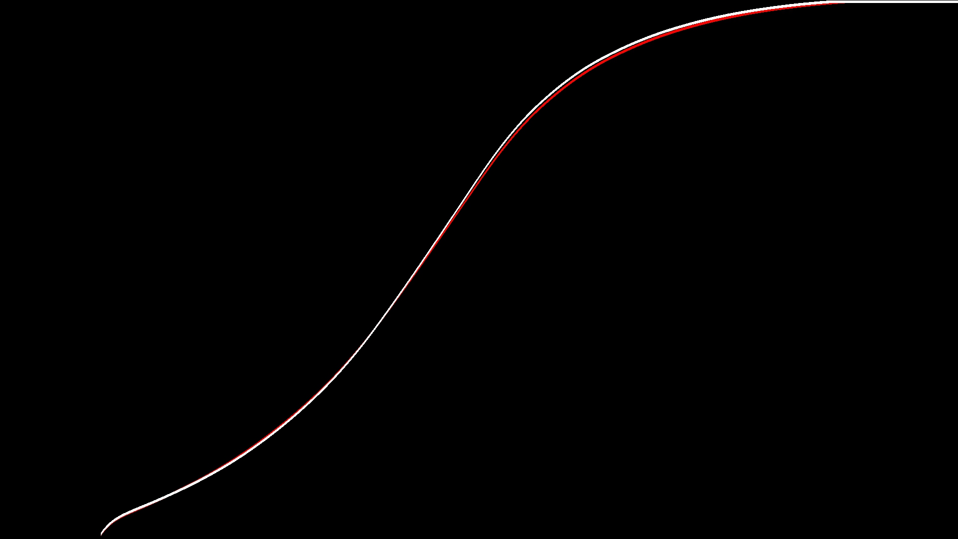
This image Shows the two curves layered on top of each other. The Curve in red represents Scenario 3 and the curve in white Scenario 1 notice the difference on the upper part of the contrast curve.

Also, if I layer the grey scale images on top of each other but change the overlay mode to multiply, it reveals the part of the curve that is really different:

The difference that exists is barely perceptible in real world images and thus I hadn’t noticed it before when testing the “pseudo” Workflow but with these tests I now realised it’s there and it’s really bugging me.

This testing only proves that there is a difference in DaVinci’s processing when using the specific ACES version, IDT and ODT combinations I didn’t test any others so I won’t assume anything.

If anyone has any insights I’d love to hear them. I’l probably post this on Blackmagic’s forum and Lift Gamma Gain to try and find some more insight :slight_smile:

Scenario 1: Setting Resolve’s Colour Science to ACES on the colour management preferences using:

  • Colour Science: ACEScct
  • ACES Version: ACES 1.1
  • ACES IDT: Alexa
  • ACES ODT: Rec.709
  • Preset Node LUTs in: ACEScc AP1 Timeline Space
  • No other nodes or colour corrections applied

Scenario 2 uses a “pseudo” ACES workflow using ACES Transform OFX plugins o two nodes:

  • Colour Science: DaVinci YRGB
  • Timeline Colour Space: Rec.709 Gamma 2.4
  • Node one ACES Transform OFX plugin is set to:
    • ACES Version: ACES 1.1
    • Input Transform: Alexa
    • Output Transform: ACEScct
  • Node two ACES Transform OFX plugin is set to:
    • ACES Version: ACES 1.1
    • Input Transform: ACEScct
    • Output Transform: Rec.709
  • No other nodes or colour corrections applied

Scenario 3 is creating a 128sized CUBE LUT in Lattice that concatenates 5 ACES CTLs and then processing the files using that LUT in DaVinci Resolve.

  • Lattice CTL Sequence in ACES 1.1 is:
    • IDT.ARRI.Alexa-v3-logC-EI800.ctl
    • ACEScsc.ACES_to_ACEScct.ctl
    • ACEScsc.ACEScct_to_ACES.ctl
    • RRT.ctl
    • ODT.Academy.Rec709_100nits_dim.ctl
  • Resolve Settings are:
    • Colour Science: DaVinci YRGB
    • Timeline Colour Space: Rec.709 Gamma 2.4
    • 3d Lookup Table Interpolation: Tetrahedral

Original DPX test files and result DPX files on the link below for anyone interested:
Download DPX Files (Dropbox)

Have you tried with a different IDT? ARRI IDTs have a slightly different LogC to linear transform at different EI settings, but you don’t get to select the EI when choosing “Alexa” as the Input Transform in Resolve (or most other grading systems). I wonder if ACES mode, and the OFX ACES Transform use a different EI version of the LogC curve? The difference is minimal, and as soon as you start grading, the changes you make are far more significant. But when you want different pathways to match exactly it can be frustrating.

Most other cameras use the same log curve at all EIs.

Hi Nick, no I haven’t tried other IDTs, I’ll probably give it a go tonight when I have a break.

Indeed the differences are minimal and as per the post, when I put the adjustment on real world images and compared stills from the “pseudo” ACES workflow to the ones from a normal workflow I couldn’t tell the difference.

Only by looking at the curve and layering images with a difference blend mode did the change become apparent.

I wonder why the OFX plugin would use a different IDT than the Colour Management system though? Seems a bit odd specially since you are not given a choice.

Anyway, that’s a good insight and I did notice that ARRI has more IDT versions than any other camera at the ACES repository.

I’ll have a look and post more results later.

Hi Nick, so it seems you were spot on the right track.
I did the same batch of tests but this time trying to find some more unambiguous IDTs.

I ended up testing both IDT.Sony.SLog3_SGamut3Cine and the Blackmagic Design Film IDT and with them, indeed there is no difference whatsoever in the result.

It seems then that the OFX plugin is choosing a different IDT for the Alexa then the colour management system.

I’ll try and find out which but at least it really seems to be only an IDT choice issue and not anything else in the chain of operations.

It also means that apart from the odd automatic IDT variant choice, the “pseudo” ACES workflow is rock solid in terms of it’s transforms which is a comfort :slight_smile:

Thanks for the tip.

Hi Theo, I would like to know if you get any improvement on your method when using Arri? I haver a high budget shortfilm coming and I kind of being the colorist/postpo supervisor. As I work mainly in ACES I wanted to use your method and spice up some stuff between the 2 transforms to help the DP.

Hi Fabian,

I’d say you can go ahead and use it. The fact is, even though there is a discrepancy, the difference is so minor as to be almost invisible perceptually so I wouldn’t really worry about it.

As per Nick suggestion above, I believe the difference was really only the transform node using a slightly different variant of the Alexa IDT but since you are in a float point environment it’s really not an issue.

Do bear in mind that if you are traveling to smaller colour spaces and depending on the adjustments and transformations that you are doing there, you could possibly clip data before you travel back to ACES. Just make sure you do some testing and that it works for you.

I do think the ACES Transform nodes are pretty rock solid though and I’ve been testing/using them for a while.

Thanks Theo, mainly I will use it, to make a viewing LUT for the shooting with 1 underexpose between the transforms since the dp tends to go extremely low to the point of crushed blacks.

If you never tried, Lattice has a great tool for generating precise exposure adjustment LUTs (which can be very high resolution 1D LUTs) for most colour spaces/gamma pairs including ACES.

Here is a link for a sample -1 Stop in ACEScct AP1 exposure change if you want to try:

1 Like

I know about lattice, I’m planning on VM my windows machine only for it!!! I did try the method and I also compared with the Luts provided by Antler Post I didn’t saw any big difference. We used it on the shooting and It worked as intended.

Thanks!!!

You can export DCTLs and LUTs from within Resolve using ACES 1.1 OFX Plugin. Exposure can be adjusted too.

1 Like

Hi Theo. I’m noticing a big difference in look in resolve using ACES mode compared to the same LUT in Lattice. It seems to appear a little greener, less contrast and less saturated in resolve.

I basically exported a LUT created in lattice within Acescct. I get the desired result in Lattice, when adding the CTL concatenations of

  • ACEScsc.ACEScct_to_ACES.ctl
  • RRT.ctl
  • ODT.Academy.Rec709_100nits_dim.ctl

However in Resolve using ACES mode.

  • Colour Science: ACEScct
  • ACES Version: ACES 1.1
  • ACES IDT: Alexa
  • ACES ODT: Rec.709
  • One node with the previosuly exported LUT in Acescct.

I see a noticeable difference between Lattice and Resolve. Any ideas why? I am using resolve 16.

Hi David, I think you are forgetting a few CTLs there in Lattice. The whole chain should be:

  • IDT.ARRI.Alexa-v3-logC-EI800.ctl
  • ACEScsc.ACES_to_ACEScct.ctl
  • ACEScsc.ACEScct_to_ACES.ctl
  • RRT.ctl
  • ODT.Academy.Rec709_100nits_dim.ctl

I did test it before and it was virtually identical to the resolve look un less something changed with the latest versions.

Well that’s the thing. The LUT was created in the Acescct space so the IDT portion should be irrelevent no?

Not at all unless you had a camera that shot into the ACES colour space and gamma natively (As far as I know, no camera in the marked does that). You still have to use the IDT to bring your camera gamut and colours to the right place before your aces look is applied.

The way you do it is you apply your look between the

  • ACEScsc.ACES_to_ACEScct.ctl
  • ACEScsc.ACEScct_to_ACES.ctl
    CTLs (that is if your look is made for ACEScct)

I’m assuming you are trying to make a monitoring LUT for a specific camera?

I see. So perhaps you can guide me as i explain what was actually done and where i went wrong.

Basically i was trying to reverse a kodak emulation lut that should be applied to alexa log c footage into the acescct color space.

Here was my workflow in Lattice.

  • Changed color space from Alex WIde gamut/Log C to Rec709/Log C
  • Combined Resolve’s Kodak 2383 Emulation Lut (This is the desired look)
  • I then applied an inverse CTL
  • InvODT.Academy.Rec709_100nits_dim
  • InvRRT
  • ACEScsc.ACES_to_ACEScct.ctl

This should give me the desired result in an Acescct space. I guess i misunderstood?

What is the specific gamma and colour space that the LUT expects as an input and what gamma/colour space does it output?

The emulation lut expects rec 709 color space and log C gamma. The output is in rec709/rec709

Ok so try the following in Lattice. Bear in mind it may not work perfectly because of the middle few steps.

First create a blank new LUT in Lattice, preferably a 65^ cube.

Concatenate the following CTLs:

  • IDT.ARRI.Alexa-v3-logC-EI800.ctl
  • ACEScsc.ACES_to_ACEScct.ctl

Then using Lattice’s Convert Colour Space function set it to:

Source: ACES Primaries 1 | D65 | ACEScct

Destination: Rec. 709 | D65 | Arri LogC EI800

Then use Lattice’s Combine function to add your film emulation LUT on top of all that.

After that, do another Lattice Convert Colour Space function and set it to:

Source: Rec. 709 | D65 | BT.1886

Destination: ACES Primaries 1 | D65 | ACEScct

Then concatenate the following CTLs:

  • ACEScsc.ACEScct_to_ACES.ctl
  • RRT.ctl
  • ODT.Academy.Rec709_100nits_dim.ctl

The middle step that I described basically makes your LUT’s input to expect ACEScct AP1 and it’s Output to be ACEScct AP1 as well.