ZCAM for Nuke

That’s a proper question. I have been advocating for the past year (or more ?) to developers for a proper implementation of the “color_picking” OCIO role in DCC softwares, which would let you define the color space of your “color selection”. So the color space used to choose colors would be different than your actual working/rendering space. Only Autodesk Maya has this implementation for the moment.

I also know that Thomas has written a plea for Colour Analysis Tools in DCC Applications and that Derek has setup OCIO configs where the color picking role would be slightly desaturated using a Matrix Transform. So there is interest on this particular matter in the CG industry I would say.

On the other hand, I also know that some color peeps think that limiting the input/stimulus range is just a “flashing sign” for a flawed system. I will let everyone make their own opinion on this specific topic.

That’s actually what I have been recommending to a few studios recently. Until Wide Gamut rendering and display is figured out, I feel it is safer to have the same primaries for both rendering and display. I mean, we did render the Lego movies in P3D60, right ?

Chris

That’s reasonable, but only possible if the scene the DP is looking at can be fully contained withing the gamut and dynamic range of the display. Which realistically limits you to indoor diffuse lit scenes with non challenging objects.

What does neutral mean when things leave this zone?

The intent with the ZCAM based approach is that the axis we’re pulling in on is at least theoretically perceptually “neutral” in terms of hue. And trading off chroma for brightness as we run out of headroom.
Now is it actually doing that? I’m not sure.

1 Like

There’s another nuanced take on this rather complex surface. What is a sane context where expectations can be met?

For example, if we have someone sitting with a ColourChecker 24 on their desk, and they represent the values in a stimulus encoding, is it sane and reasonable for the values to be rather close on their BT.2100 display and their sRGB display? Open question, with at least two possibilities:

  1. The stimulus encoding footprint is ground truthed against observer sensation metrics. There will be very little chance that the observer sensation will match further down the line. See ZCAM and any other observer sensation based distortion at this extremely early juncture in the working stimulus encoding domain.
  2. The stimulus encoding footprint holds true to stimulus linear compression. The observer sensation stands a chance of being closer to “similar” after other observer sensation distortions / manipulations for technical reasons. This would be close to a ground truth of light transport, albeit buried in the limitations of RGB stimulus encodings of course.

Which is part of this dilemma. We are already “working” on values, and relative to the working stimulus encoding, only some values will hold meaning. The rest cease to maintain meaning. Seems like a bridge that is likely forced to be crossed here.

Is there a choice?

It isn’t like this is optional, given that no matter how much people hope and wish, every single stimulus encoding fed to an output will be manifested as some actual stimulus. Given that the range of stimulus encoding to actual stimulus output varies based on the output medium, this makes the output unknown.

I’m completely in this camp.

It’s an expressive medium, and folks should be permitted to express within it, to the greatest limit of the medium. Dominic Glynn talks about this briefly in his interview where he discusses forming higher order colour sensations using illusory effects.

So what if, Glynn proposes, a scene in a movie added, subtly, light in a very specific wavelength of green? Then just kept ramping up, more and more green—and, at a key moment, the screen dropped all the green out at once. The movie would induce the complementary color as an afterimage. You’d imagine you were seeing a specific red, not projected on the screen but as a neurophysiological response to stimulus. And if you pick the precise wavelength, “you could actually cause someone to perceive a color that they could never otherwise see. Like, there’s no natural way for you to have the perception of that color.”

Again, it isn’t like there has ever been an option here as best as I can tell. Whether we like it or not, every single stimulus encoded will get spit out as something. That something can either vary from output medium to output medium, or a management system can seek to control it.

2 Likes

I don’t have the Nuke chops to do any CIECAM02 comparison plots, but I can easily animate a line plot of, for example, JzAzBz hue (or ZCAM hue) over the entire luminance range before and after the DRTs and see what we see. I’m not sure if that tells us anything useful, but I guess it would show how much they deviate and show any hue skews. Does that sound like something you were after?

A big caveat here: I’m not sure if this is the best or the correct way of plotting this. Is any of this relevant? Color scientists can answer that. Also forgive me for butchering any color science terminology in the text below. The nuke script is attached for those that want to play.

So this shows JzAzBz hue correlate (green line) of the scene linear values and ZCAM hue correlate (blue line) of display linear values after the DRTs. The x-axis is the entire luminance range of 14 stops compressed at the display side of course to 0-1 range. The y-axis is hue angle from 0 to 360, which I’m changing 5 degrees every frame. sRGB output transform.

DRT ZCAM v07: With ZCAM we can see what I pointed out earlier with the 3D plots is that the colors never hit the display white unlike with the other two DRTs. This seems to make the line follow much closer to the scene side hue line. If I plot this without doing gamut compression/mapping in the DRT the hue would not be as close, as @alexfry already demoed early on: ZCAM for Nuke - #9 by alexfry, there would be hue skews.
drtzcam_hue

OpenDRT v0.0.90b4: With OpenDRT the biggest differences come from the clamping of the chroma “balloon” over the cube. Some of the hue differences come from the perceptual dechroma while with some other hues the perceptual dechroma helps to reduce the skews.
opendrt_hue

ACES 1.2: Just threw this for visual comparison.
aces_hue

Here’s the nuke script: plot_correlates.nk (589.5 KB)

1 Like

I’ve been wondering if using a CAM can help us deal with some of the perceived colourfulness effects of higher brightness levels.

The image below is from the Ed Giorgianni ACES background design document posted by @Alexander_Forsythe here: ACES background document

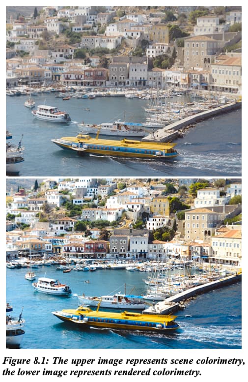
8.1. Why is Rendering Needed?
Figure 8.1 above illustrates the effects of display- image rendering. The upper image represents original scene colorimetry, and the lower image represents the results of rendering that colorimetry for output.

The images demonstrate that although scene-space images may be colorimetrically accurate, when displayed directly they are perceived as “flat” and “lifeless”. The fundamental reason rendering is needed, then, is to translate original-scene colorimetric values to output colorimetric values that produce images having a preferred color appearance.

Currently, both @matthias.scharfenber and I have mapped 1.0 in ACES scene linear to 100nits as our entry point into the ZCAM model. But that doesn’t need to be case, and may not be a particularly sane starting point for daylight scenes. Could the ZCAM model be used to help simulate the appearance of high intensity daylight colours on low brightness displays?

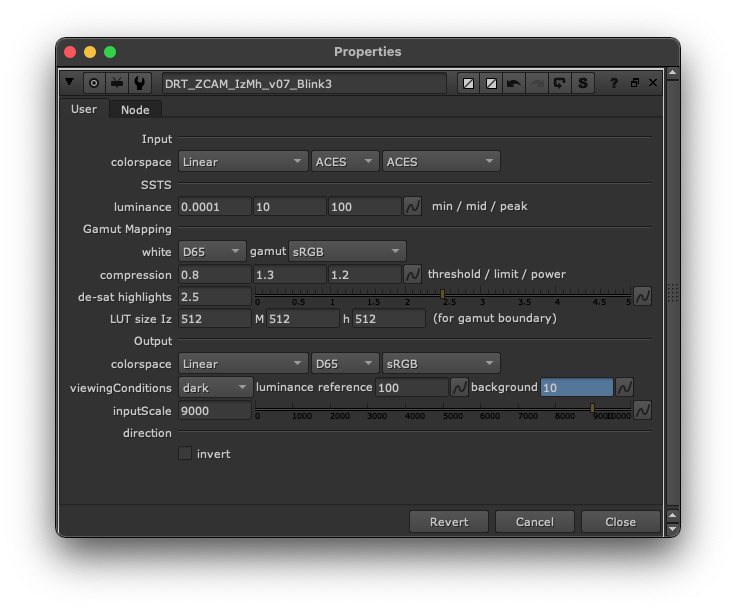
I made a slightly modified version of @matthias.scharfenber’s DRT_ZCAM_IzMh_v07 node, with an additional control to change the scaling of the input data before it get’s transformed into it’s ZCAM components, whilst leaving the parameters of the target display as is (100nits)

Almost all of the existing sample images I’ve been using have been either full CG, or nighttime images, so I dug out some old D600 RAW .NEF images and debayered them to ACES in dcraw (metadata inferred IDT only).

To come up with a new nit value to peg 1.0 to, I’ve used the following logic.

  • Through some slightly handwavy experimentation, I believe 100nits maps to 1.0 at an EV of around 8.5
  • These images are all taken in the full blazing Australian sun, which should be an EV of around 15
  • A value of 100 exposed up by 6.5 stops (15 - 8.5) gives a value of 9050.96680 (which I’m rounding off)

So I’m mapping 1.0 to 9000nits
(Yes, there is a bunch of fudge in here, but I think it should be ballpark ok for now)

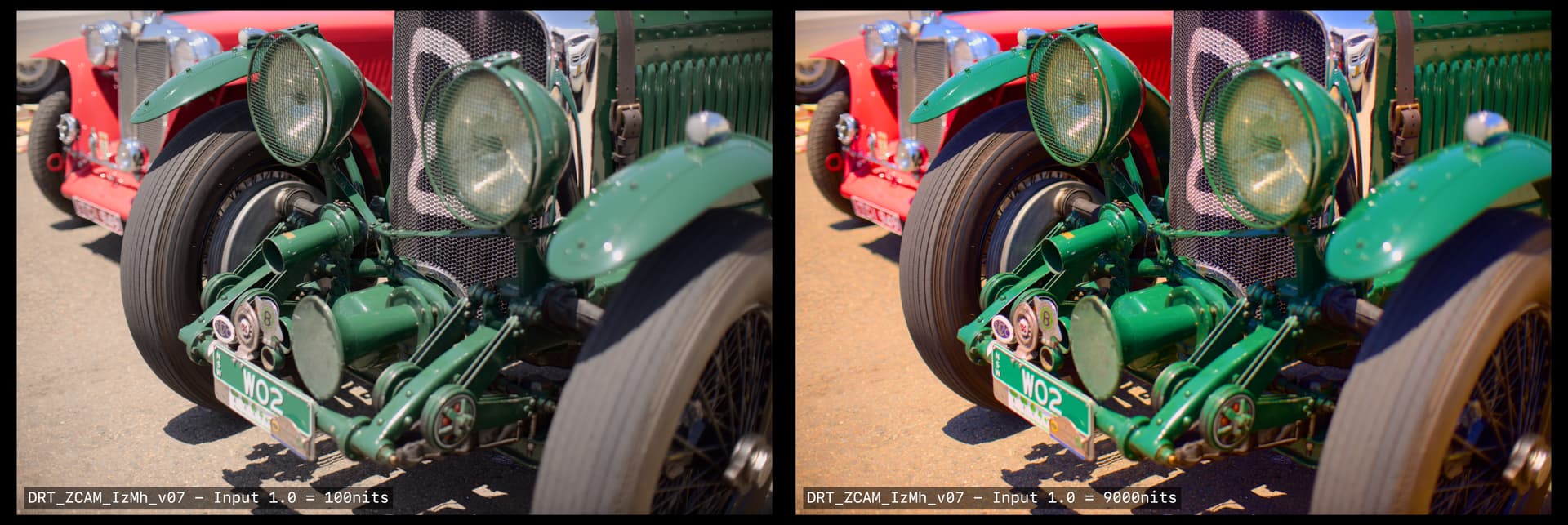
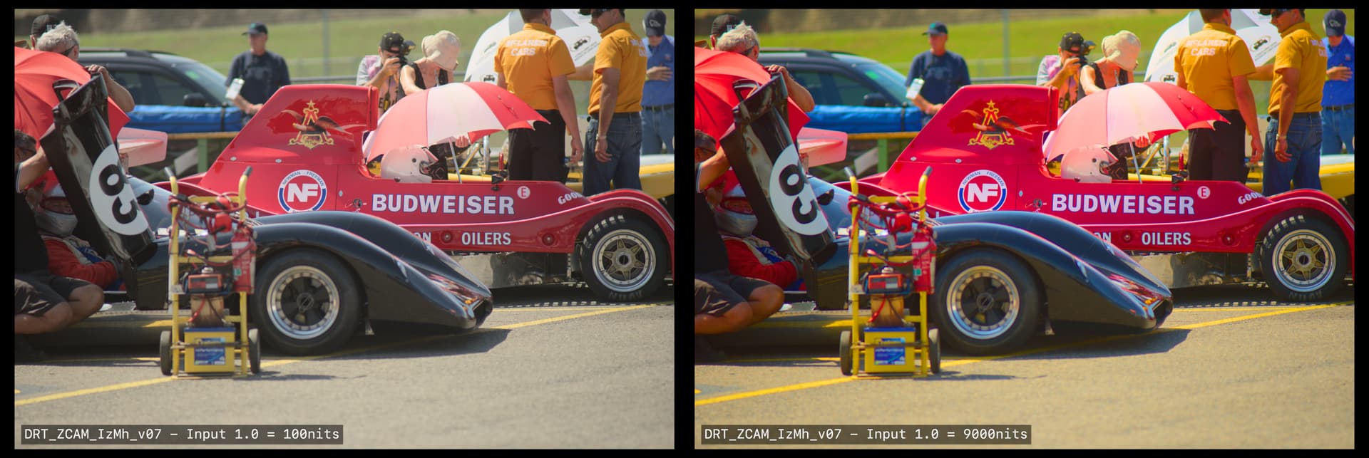
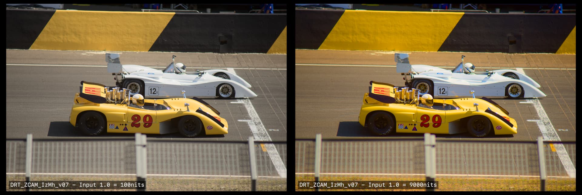
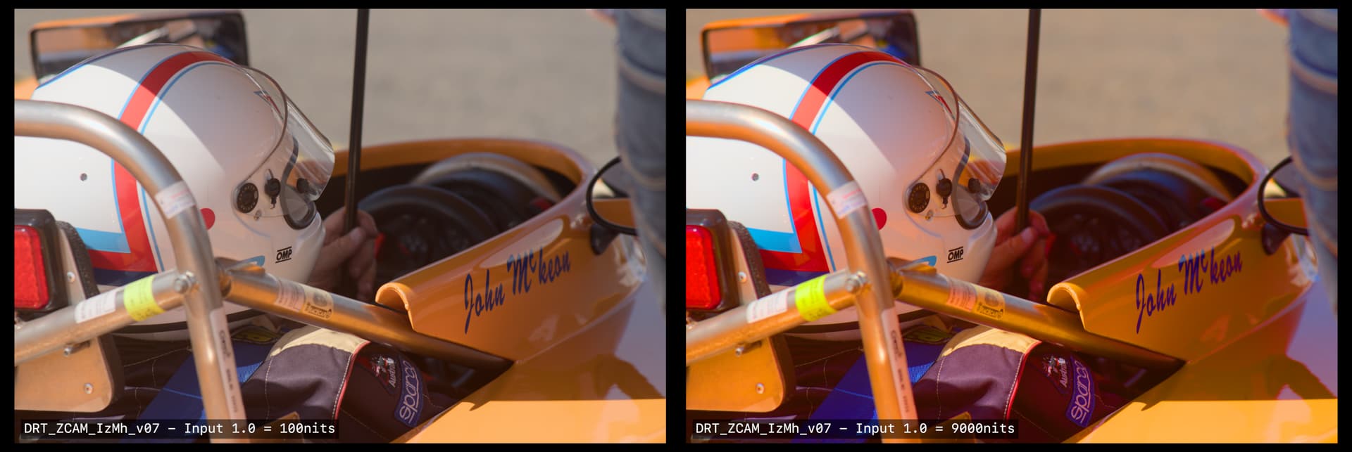
The frames below all show:
Left | DRT_ZCAM_IzMh_v07 with ACES input 1.0 mapped to 100nits
Left | DRT_ZCAM_IzMh_v07 with ACES input 1.0 mapped to 9000nits


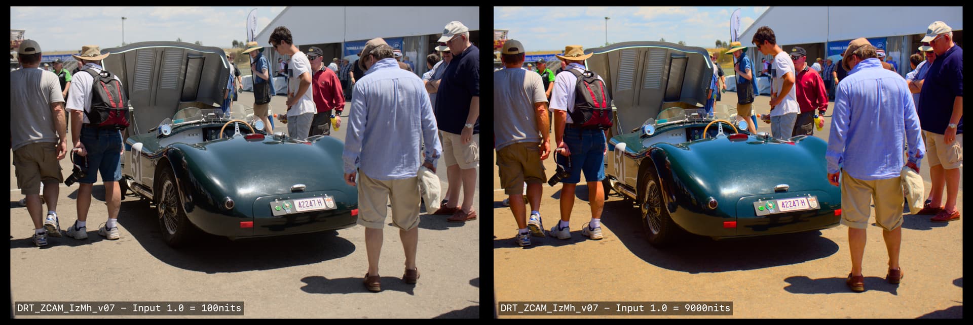
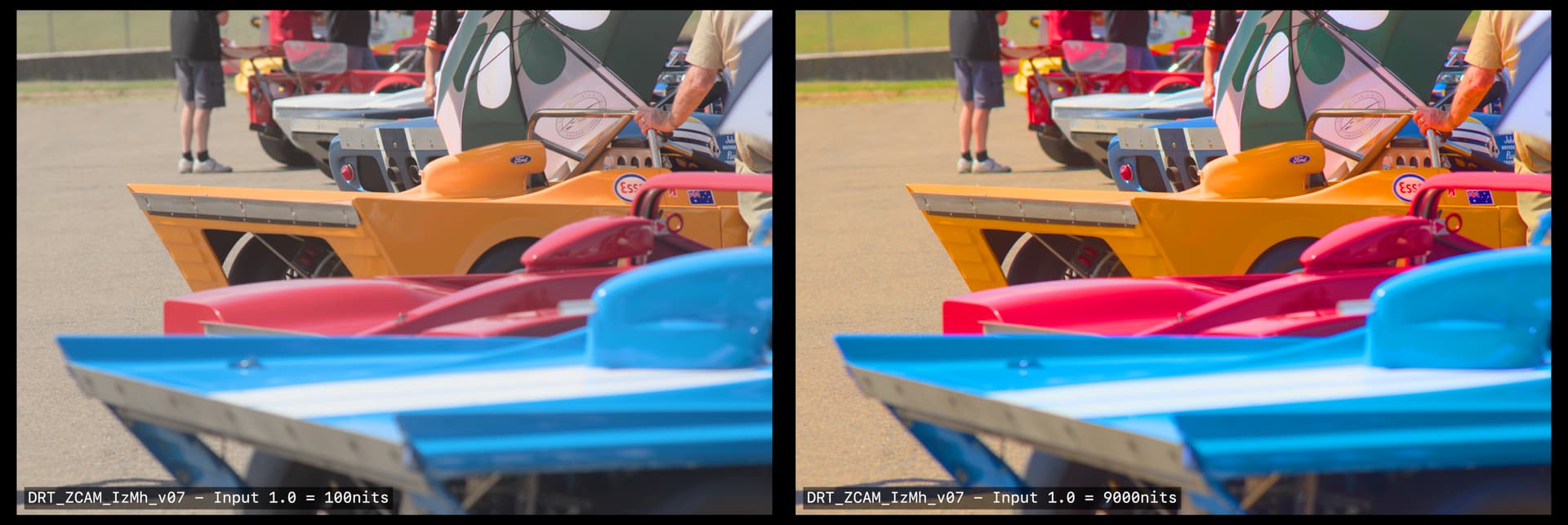
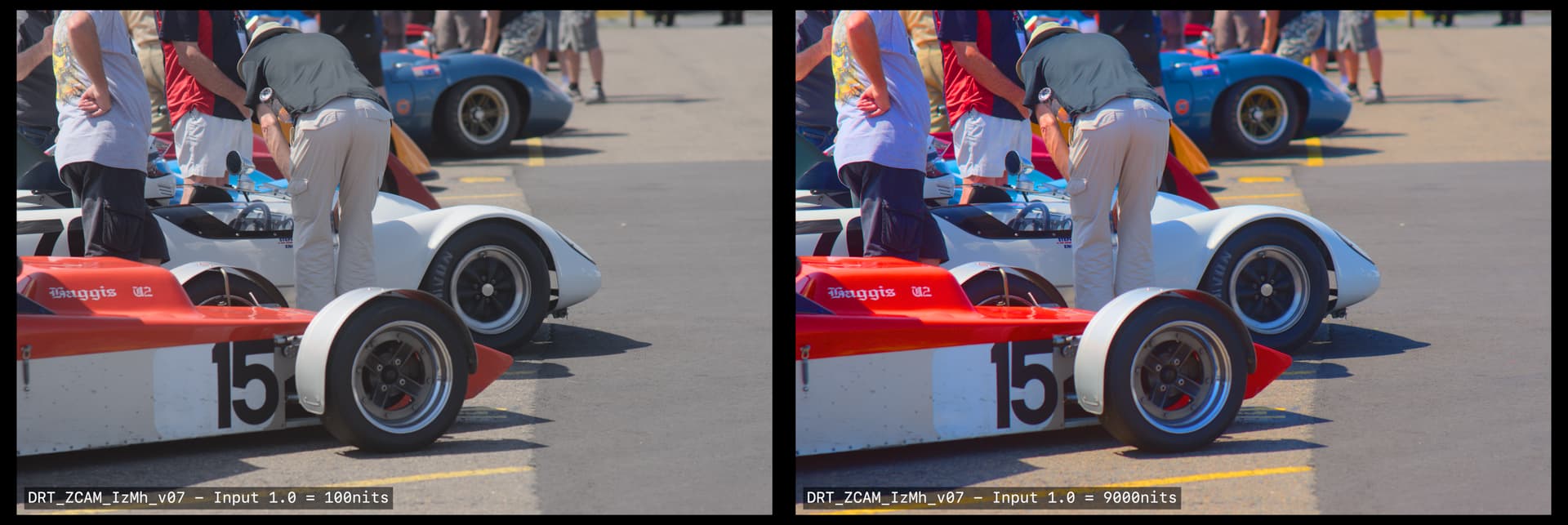
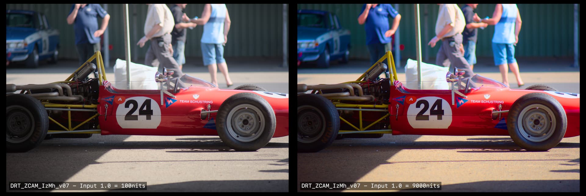
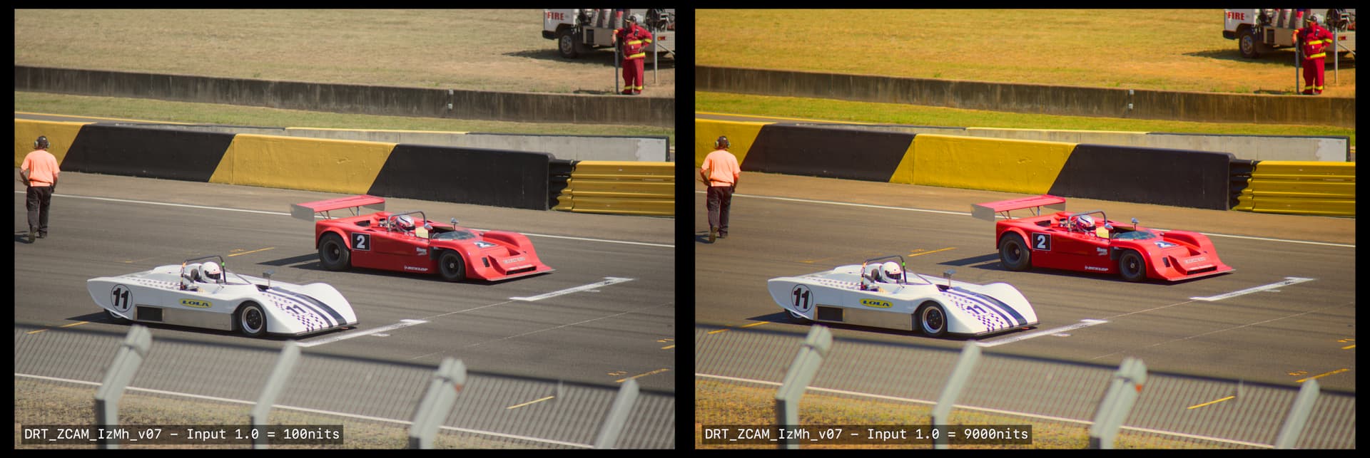
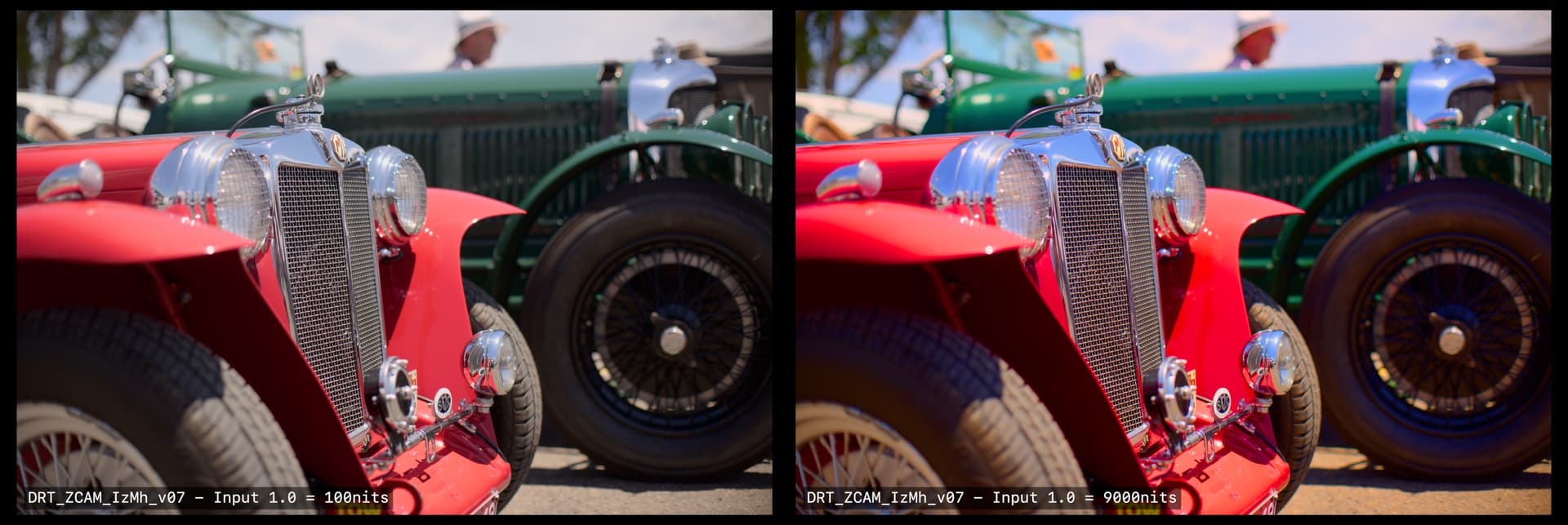
So which feels more like a bright sunny day in Australia?
Do the skintones explode to red?
Does the ZCAM model still map to perceived reality at these sorts of levels?
And what would be the point of going down this road?

In my head there is a sort of idealized scenario where camera metadata seamlessly makes it through to the display transform, and feeds in the absolute brightness of the scene. But realistically I think there are two more plausible options.

  1. It could help lead to a different standard value for mapping 1.0 into the model (Real scenes are unlikely on average to have 1.0 sitting at 100nits)
  2. Maybe you could have a sensible default, but leave the input EV open as parameter.
3 Likes

From the meeting…

@nick:

The idea of kind of being able to slightly exceed the display gamut and having a clamp as a sort of a master in clickable.

I find it peculiar how this idea comes up over and over again.

How can this work?

Every single stimulus encoding present in the headed-for-display encoding will be rendered as something. That something is fundamentally unknown if this is permitted. It strikes me as problematic in a system that is now aspires to be a management system?

Example:

In medium A, the image formation yields code values that escape the medium A’s expression range, either below zero percent or above one hundred percent contribution. Those code values are emitted as as some stimulus, always.

Where do we sample the code values for to render into medium B? The open domain stimulus encoding heading to Medium A? If so, those values that are escaping are rendering differently between Medium A to Medium B. All layers of appearance matching appear impossible at this point, as we have created a medium dependency in the encoding.

If we sample the closed domain stimulus code values at the Medium A, then we have an idea as to what stimulus is being expressed, but that’s another rabbit hole.

It feels like there is no control being expressed about what is being sent to a medium, which would appear to undermine everything attempted here?

@Alexander_Forsythe raised an incredibly relevant point here possibly?

The one thing that I was particularly interested in is looking at the perceptual correlates before the transform [the] gamut mapping / compression step and then after the gamut mapping compression step to see […] how are things being effected by the gamut compression and moving […] to observe display code values.

I believe this ties in, with rather large implications on the resultant imagery formed, to the explorations Daniel has been doing regarding gradients via the gaussian overlaps. The nature of the footprint compression will impact the projection of gradations into the destination volume. This will be manifest rather noticeably as a disruptions of smooth brightness / chroma tonality in shallow depth of field / blurry regions that have high levels of excitation purity differences? Flowers, high chroma lit objects, etc.

I think oscillating radial sinusoidal patterns could help to form a reasonable test bed here, oscillating from one highly excitation pure region to another different radial angle? I know that similar patterns have been used to derive resampling tests to much effect?

1 Like

No. I obviously wasn’t clear. I am not proposing sending code values to any display beyond what it is capable of displaying (ignoring the fact that e.g. many P3 displays don’t cover 100% of P3). The clamp would normally be applied as part of the mastering. I was merely thinking that if the clamp wasn’t hard coded into the DRT it would open up the possibility of archiving an unclipped version for safety and future flexibility.

It’s the same as limiting a Rec.2020 master to P3, because if you make the mastering clip independent of the DRT and target display (as Baselight already does) you have more flexible options.

Also bear in mind, as @matthias.scharfenber said in the meeting, the intent is that you keep the slope finite at the boundary, to aid inversion, but you set the compression parameters such that no value you would normally expect to go into the DRT will produce a result that surpasses the target gamut boundary. But a colourist is able to push values hard up against the clipping point if they want (and see the results on the monitor as they do so, in order to ensure they are happy with any resulting skews). With a DRT which is asymptotic at the gamut boundary, this is not really possible, no matter how hard the colourist turns the knobs.

From the meeting:

@matthias.scharfenber:

… I needed to clamp the output to 0-1 or I had some instability.

With the DRT ZCAM those steps in the hue lines we see in the animation in ZCAM for Nuke - #95 by priikone all come from that clamp after the XYZ-to-display matrix. Without that clamp we see this:
drtzcam_hue_noclamp

But I noticed that the values go out of gamut with any amount of chroma. Even 1% chroma will cause values to go outside the display gamut (at the top end, a very very small amount). Is that expected?

@daniele:

For further fitting through the DRT, predictable behavior is desirable. For grading I disagree. It would be boring to grade through.

This discussion was really interesting. From the beginning there’s been desire for “hue linear” behavior in the new DRT (whatever that is has not been defined entirely, I think) and what, I think, we can see with the DRT ZCAM is very linear hue lines over that luminance range (animated above) compared to OpenDRT. What you can’t see in the original animation is that with lower chroma the OpenDRT also becomes more linear over a larger luminance range. This is with 50% chroma:
opendrt_hue_50

So if there is going to be Default LMT that is going to be the one that people grade through typically (?) then this is not necessarily an issue with ZCAM just like it isn’t with OpenDRT. OTOH, if you want the most linear behavior then without the Default LMT you could have that with DRT ZCAM.

@Alexander_Forsythe:

I think we should work out how to get this out there for testing.

Definitely. That will show how it feels to grade through a DRT like the DRT ZCAM without Default LMT. The blue hew skew probably needs to be addressed somehow before testing.

Edit: I noticed that I messed up the stops in all of the animated plots. It’s many many more stops than 14 stops (it’s 20+ stops).

This again, seems to contradict the idea of managing the values.

Correct me if I’m wrong, but if we pretend that any of these models are Cartesian 3D cubes, what you are proposing is to permit values to exceed the cube in order to hit a target stimulus coordinate. That seems like a glaring fault in only the compression function, not specifically the model here?


Given the blue arrow forms the “tension” of the compression, if the compression is using the proper axis within the domain, it could be tensioned right out tightly to the corner.

It seems that permitting an encoding value to represent meaningless-with-respect-to-medium values is a problematic method that will achieve a random, per device dependent output?

Would it not make more sense to provide a sensible encoding that is known, and an optional first-order gamut compression with relaxed, and proper, tension?

Then it means an encoding that is device dependent again. This undermines the very essence of a management system. Surely we have enough evidence of this already to suggest that perhaps it’s a faulty vantage?

How does one define uniform and consistent looks under such a system, when the results are device dependent? Is this not precisely the pre-existing condition of the fundamental design problems in ACES as it currently exists?

What am I missing?

Isn’t that exactly what colours with CIExy coordinates outside the spectrum locus do? They are “meaningless” but we preserve them through processing so we can decide what best to do with them.

2 Likes

I don’t think so? It depends on what it is relative to. Given ARRI dominates this space, it’s probably fair to say that folks push around AWG values, and then go back to LogC, and onward. Relative to the camera observer stimulus encoding, those values hold meaning, and given the vast majority of the efforts out there that use ARRI pipes, it’s fair to say that they begin and end life as AWG, not CIE xy.

With that said, it doesn’t address the point that if we are specifying meaningless values in an encoding, we’d end up knee deep right back in device dependency again, right smack dab where the mess is now.

I’m open to the idea if someone is able to explain how that works in a system that is attempting to appearance match. What is the intended stimulus? How does such a system appearance match something that doesn’t actually mean the same thing across different devices?

If the ultimate input is xy Foo, and medium A can’t represent it, so it represents it as something else, and medium B also can’t represent it, so it represents it as something else again, and medium C also can’t… so it represents something else… rinse and repeat. Seems to me it’s right back where the mess started, which is where it is now.

2 Likes

Well… In all fairness, it is impossible to completely eliminate device-dependency unless the limiting gamut is something smaller than 70% sRGB as there are laptop screens that can’t even display that. With the pandemic, streaming services have become the new normal and that raises the possibility of content being seen in less-than-ideal conditions to sky high levels, e.g. on bad laptop screens in extremely bright surrounds.

Thanks to a suggestion from @TooDee I’ve now got this working:

Please note, this is still my 0.6 version of ZCAMishDRT, not Matthias’s more developed version. I’ll try and run out something similar with it before the next meeting.

3 Likes

Can you also share the file again on iCloud? Thanks.

I got some interesting results after adding optional Michaelis-Menten/Naka-Rushton to @nick 's DCTL implementation of the ZCAM model and comparing our whole set of frame captures with SSTS under different settings :

  • Default settings for everything
  • SSTS + Viewing Conditions = dim
  • MM + Viewing Conditions = dim
  • SSTS + Highlight Desat = 1.75 + GC Threshold = 0.7 + Ref lum = 200 + Y Mid = 8 + Y Max = 120 + Viewing Conditions = dim
  • MM under same modified settings
  • MM under modified settings but with Y Mid back to 10
  • OpenDRT 0.90b4 with sRGB gamma 2.2 preset
  • OpenDRT 0.90b4 with sRGB gamma 2.2 preset but corrected with an additional node to use piecewise sRGB EOTF

Please note that I’m using the version from this commit : Add full Scharfenberg ZCAM DRT with partially implemented inverse and that I’ve fixed the DCTL+Cuda errors myself. I stuck to it because it gave better results with our subtle red volumetric fog in a very dark area than the later one with high boundary gamut compression.

Please also note that I add to tweak blues to remove the cyan hue shift as it ruined sky colour (a memory colour) and also tweak the saturation in the high ranges because the DRT was desaturating way too fast at high EVs and that led to a small exposure compensation so the saturation increase wouldn’t kill the brightness sensation too much.

Final note is that I haven’t had time to fully test the model in HDR yet as I need to test it on multiple monitors with different Y_MAX and different Rec.2020 coverage.

With those caveats out of the way, here are the results I got :

  • Dark viewing conditions is too dark for game content in SDR because games are usually played in bright environments but this is not new and we already knew that so that’s why I moved to dim for further tests.
  • Dim viewing conditions with default settings and SSTS gives a good result with almost all of my footage except the scenes which have too much bright VFX in them (especially fire). By viewing our test footage under this DRT, I actually learned that there was a subtle red volumetric fog in our tutorial area that I didn’t know about because it was completely lost under OpenDRT (crushed to gray under gamma 2.2 and crushed to black under piecewise sRGB).
  • In general, Michaelis-Menten/Naka-Rushton tone scale makes everything darker but can sometimes make brights brighter.
  • The tweaked settings with SSTS hit a very sweet spot. Lowering Y_MID to 8 allows us to increase chroma (through increasing ref white and Y_MAX) and reduce highlight desat which, in turn, makes scenes with very bright VFX look way better. It also matches blacks to the darker piecewise sRGB curve which is something that is non-negotiable with our art department.
  • As it makes things darker, MM tone scale completely crushes blacks under the same conditions.
  • However, darks can be matched with MM by raising back Y_MID to 10. With this setting, we end up with more contrast when using Michaelis-Menten/Naka-Rushton tone scale from OpenDRT due to the different Y_MIDs.
  • OpenDRT 0.94b2 with sRGB preset and pure gamma 2.2 kinda matches default settings with SSTS in brightness but loses our subtle red volumetric fog (it kinda makes it gray).
  • OpenDRT 0.94b2 with sRGB preset corrected to use piecewise sRGB EOTF crushes darks to black a lot. SDR fire VFX also look way too pink. I tried correcting that with a hue shift in an experimental branch but it unfortunately twisted all red assets to orange.

Final conclusion from someone who actually used OpenDRT which was seen as a pre-alpha of ACES 2 in a shipped product : ZCAM model with SSTS looks very very promising. Next step for me is running that by our leads.

4 Likes

Trying to get a better handle on the issue @ChrisBrejon was pointing out in the other thread.

The ramps below are:
Top: sRGB 0:0:1 → 1:1:1
Middle AP1 0:0:1 → 1:1:1
Bottom: AP0 0:0:1 → 1:1:1

My assumtion is the big drop into darkness in the AP0 ramp is down to the ZCAM model not really being able to make sense of imaginary colours, that are at best, mostly near ultraviolet.

But the little dip towards the bottom of the AP1 ramp is what we’re seeing in his ramp examples.

Pre-transform they plot out like this:

As the M compression is wound in, you see something like this.

compressionWind_v001

My guess is that the model can’t really keep J/Iz perfectly stable as you yank the M and h values around?

2 Likes

I think we can see that in this hue correlate plot as well. Green line is JzAzBZ hue correlate in scene linear and blue is ZCAM hue correlate in display linear, after the gamut mapping.

Input values are ACES2065-1 AP0.

In top row the horizontal axis is chroma from 0-100%. In the bottom row the horizontal axis is the exposure approximately from -7 to +8 with 100% chroma.

The hue deviates significantly from JzAzBz over the whole exposure range (100% chroma), and that deviation is that kink we see in the top row (>90% chroma).

Edit: corrected the JzAzBz hue correlate in the image, my first post used wrong input values.

1 Like

Hey Alex,

QQ: Are the AP0 colours gamut mapped before entering ZCAM?

APO exhibit rather dramatic singularities, and the fact that its basis is rotated so much compared to usual colourspace probably does not help.

Blue to White Ramp and looking at the various correlates only (with AP0 correlates clipped to [-inf, max(sRGB Correlate)]):


The most interesting ones here are obviously, M, C and h, they point out that we cannot afford not gamut map before ZCAM, non-physically realisable colours are behaving in a rather unpredictable way.

Cheers,

Thomas

2 Likes

Not necessarily advocating this for our use case but just wanted to share this paper. Serves as a reasonable review of calculation methods of GBDs

2 Likes